US20080098562A1 - Self-propelled vehicle for cleaning roads and the like - Google Patents
Self-propelled vehicle for cleaning roads and the like Download PDFInfo
- Publication number
- US20080098562A1 US20080098562A1 US11/977,638 US97763807A US2008098562A1 US 20080098562 A1 US20080098562 A1 US 20080098562A1 US 97763807 A US97763807 A US 97763807A US 2008098562 A1 US2008098562 A1 US 2008098562A1
- Authority
- US
- United States
- Prior art keywords
- container
- recesses
- vehicle according
- refuse
- side panels
- Prior art date
- Legal status (The legal status is an assumption and is not a legal conclusion. Google has not performed a legal analysis and makes no representation as to the accuracy of the status listed.)
- Granted
Links
Images


Classifications
-
- E—FIXED CONSTRUCTIONS
- E01—CONSTRUCTION OF ROADS, RAILWAYS, OR BRIDGES
- E01H—STREET CLEANING; CLEANING OF PERMANENT WAYS; CLEANING BEACHES; DISPERSING OR PREVENTING FOG IN GENERAL CLEANING STREET OR RAILWAY FURNITURE OR TUNNEL WALLS
- E01H1/00—Removing undesirable matter from roads or like surfaces, with or without moistening of the surface
-
- B—PERFORMING OPERATIONS; TRANSPORTING
- B60—VEHICLES IN GENERAL
- B60K—ARRANGEMENT OR MOUNTING OF PROPULSION UNITS OR OF TRANSMISSIONS IN VEHICLES; ARRANGEMENT OR MOUNTING OF PLURAL DIVERSE PRIME-MOVERS IN VEHICLES; AUXILIARY DRIVES FOR VEHICLES; INSTRUMENTATION OR DASHBOARDS FOR VEHICLES; ARRANGEMENTS IN CONNECTION WITH COOLING, AIR INTAKE, GAS EXHAUST OR FUEL SUPPLY OF PROPULSION UNITS IN VEHICLES
- B60K15/00—Arrangement in connection with fuel supply of combustion engines or other fuel consuming energy converters, e.g. fuel cells; Mounting or construction of fuel tanks
- B60K15/03—Fuel tanks
- B60K15/063—Arrangement of tanks
- B60K15/067—Mounting of tanks
- B60K15/07—Mounting of tanks of gas tanks
-
- B—PERFORMING OPERATIONS; TRANSPORTING
- B60—VEHICLES IN GENERAL
- B60K—ARRANGEMENT OR MOUNTING OF PROPULSION UNITS OR OF TRANSMISSIONS IN VEHICLES; ARRANGEMENT OR MOUNTING OF PLURAL DIVERSE PRIME-MOVERS IN VEHICLES; AUXILIARY DRIVES FOR VEHICLES; INSTRUMENTATION OR DASHBOARDS FOR VEHICLES; ARRANGEMENTS IN CONNECTION WITH COOLING, AIR INTAKE, GAS EXHAUST OR FUEL SUPPLY OF PROPULSION UNITS IN VEHICLES
- B60K15/00—Arrangement in connection with fuel supply of combustion engines or other fuel consuming energy converters, e.g. fuel cells; Mounting or construction of fuel tanks
- B60K15/03—Fuel tanks
- B60K15/03006—Gas tanks
-
- B—PERFORMING OPERATIONS; TRANSPORTING
- B60—VEHICLES IN GENERAL
- B60K—ARRANGEMENT OR MOUNTING OF PROPULSION UNITS OR OF TRANSMISSIONS IN VEHICLES; ARRANGEMENT OR MOUNTING OF PLURAL DIVERSE PRIME-MOVERS IN VEHICLES; AUXILIARY DRIVES FOR VEHICLES; INSTRUMENTATION OR DASHBOARDS FOR VEHICLES; ARRANGEMENTS IN CONNECTION WITH COOLING, AIR INTAKE, GAS EXHAUST OR FUEL SUPPLY OF PROPULSION UNITS IN VEHICLES
- B60K15/00—Arrangement in connection with fuel supply of combustion engines or other fuel consuming energy converters, e.g. fuel cells; Mounting or construction of fuel tanks
- B60K15/03—Fuel tanks
- B60K15/063—Arrangement of tanks
- B60K2015/0638—Arrangement of tanks the fuel tank is arranged in the rear of the vehicle
-
- B—PERFORMING OPERATIONS; TRANSPORTING
- B60—VEHICLES IN GENERAL
- B60Y—INDEXING SCHEME RELATING TO ASPECTS CROSS-CUTTING VEHICLE TECHNOLOGY
- B60Y2200/00—Type of vehicle
- B60Y2200/10—Road Vehicles
- B60Y2200/14—Trucks; Load vehicles, Busses
- B60Y2200/144—Garbage trucks, e.g. refuse trucks
Definitions
- the present invention relates to a self-propelled vehicle for cleaning roads and the like, suitable to operate over vast areas and with extended work cycles, as described in the preamble of claim 1 .
- road cleaning vehicles and the like are utilized to remove refuse and pollutants from the environment. It is therefore desirable that they do not in turn release pollutants into the environment.
- This drawback is important for road cleaning vehicles, as they must perform cleaning operations that last for several hours, if possible without stops or detours to refuel.
- This container must be very large to allow extended work cycles and so that the refuse collected does not require to be transported to a dump or the like several times a day.
- the container must also have a tipping mechanism, to allow fast emptying operations.
- the considerable added weights must not produce excessive local stresses on the road sweeping vehicles or compromise the stability thereof, or limit the driving or maneuvering speed along roads and work areas.
- the technical aim of the present invention is to devise a self-propelled vehicle for cleaning roads and the like capable of substantially overcoming the aforesaid drawbacks.
- an important object of the invention is to realize a vehicle with low pollution, reduced operating costs and a high fuel range.
- Another important object of the invention is to realize an internal combustion self-propelled vehicle for cleaning roads and the like having correct balancing of masses.
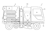
- FIG. 1 shows a side view of the vehicle according to the invention
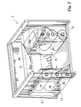
- FIG. 2 shows an axonometric view of a part of the vehicle according to the invention.
- FIG. 3 shows the part in FIG. 2 in a top sectional view.
- the vehicle according to the invention is indicated as a whole with the number 1 .
- chassis 1 a extending prevalently in a longitudinal direction 1 b and lateral sides 1 c substantially parallel to said longitudinal direction 1 b.
- a fuel gas such as LPG and preferably natural gas
- an engine 2 suitable to utilize the fuel gas
- wheels 2 a driven at least in part by the engine 2 .
- driving means 14 and above all a large container 3 for refuse and pollutants, functionally associated with conveying members 4 suitable to convey refuse and pollutants from roads and various surfaces or areas towards the conveyor 3 .
- the container 3 has side panels 3 a provided with recesses 15 expanding toward the inside of the container 3 and extending substantially above the lateral sides 1 c of the chassis 1 a , and in continuity therewith.
- the storage apparatus 5 is realized by a plurality of tanks suitable to contain the fuel gas and disposed at least prevalently in the recesses 15 .
- the tanks 5 are supported by the chassis 1 a , by means of an adequate rigid lattice.
- the recesses 15 are connected to the side panels 3 a of the container 3 by means of connecting walls tilted in a manner suitable to facilitate the flow of refuse inside this container 3 .
- the recesses 15 are also dimensioned and shaped in a manner suitable to allow the container 3 to be raised without interfering with the tanks 5 , integral with the chassis 1 a.
- the internal combustion engine 2 utilizing LPG or preferably natural gas—can be similar to the natural gas engine produced by “Iveco Motors” and denominated “NEF CNG engine”.
- This engine has a displacement of 5.88 dm 3 , a rating of 147 kW and a maximum torque of 650 N/m. It also has an average consumption of 245 g/kWh, dimensions of 891 mm by 831 mm by 1041 mm and a weight of almost 0.5 tons.
- the engine 2 can also be operated—in addition—with different fuels, such as petrol or diesel.
- the vehicle 1 comprises members to contain both fuels: gas and petrol or diesel, and utilizes one or the other according to the conditions.
- the engine 2 can be flanked by a secondary engine, such as an electric engine.
- the vehicle 1 has driving means 14 associated with a cab and at the rear of the cab and substantially contiguous therewith is an area 14 a to house the engine 2 .
- the refuse conveying members 4 and the container 3 are then provided in sequence, substantially contiguous with the area 14 a.
- the conveying members 4 can be of different types.
- the conveying members 4 can comprise a vertical transport mechanism 6 with a conveyor belt or chain fed by at least one brush 7 provided on the bottom of the vehicle 2 and in contact with the road or the like.
- the vertical transport mechanism 6 can operate by means of pneumatic suction of the refuse, or in yet another manner.
- the container 3 is instead realized by a closed container, the outer walls of which approximately define a parallelepiped.
- the container 3 comprises a wide front inlet 8 for the refuse and pollutants (broken line in FIG. 2 ), preferably realized by a rectangular opening positioned on the front face 8 a of the container 3 .
- the front inlet 8 has a width close to the width of the container 3 , between the side panels 3 a , and is positioned in the upper portion thereof.
- a rear discharge door 9 for the refuse is also provided.
- the container can be tipped by means of a specific tipping mechanism 10 , realized by fluid dynamic cylinders or the like. Tipping of the container 3 allows fast discharge of the refuse through the discharge door 9 .
- the container 3 also preferably comprises a wide filter system 11 for the particles of pollutant, appropriately positioned in the upper portion of this container 3 and coinciding with the door 9 .
- the filter system 11 preferably comprises a filter 12 , suitable to retain the particles of pollutant and realized, for example, by a bag filter or by an electromagnetic filter or yet again by an absolute filter, and an air suction fan 13 , suitable to convey the air containing particles of pollutant and present in the container 3 through the filter 12 and subsequently into the outside environment.
- a filter 12 suitable to retain the particles of pollutant and realized, for example, by a bag filter or by an electromagnetic filter or yet again by an absolute filter
- an air suction fan 13 suitable to convey the air containing particles of pollutant and present in the container 3 through the filter 12 and subsequently into the outside environment.
- the container 3 defines lateral housings for the tanks 5 .
- lateral housings are realized by said recesses 15 of the side panels 3 a and of the base of the container 3 . They suitably have a length, in the longitudinal direction of the vehicle 1 , ranging from 1.5 m to 2 m, a height ranging from 1.5 m to 2 m and finally a width ranging from 0.3 m to 0.7 m.
- the recesses 15 have a rear wall, in the vicinity of the door 9 , and a preferably flat and vertical lateral wall.
- an upper connecting wall 15 a is provided, realized by a surface—preferably flat—tilted with respect to a horizontal plane so as not to provide a surface to retain refuse and so as to facilitate a flow of refuse fed from above.
- a front connecting wall 15 b is provided, suitably realized so as not to have areas in which refuse accumulates and not to create corners that are difficult to access on the base of the container 3 in a position opposite the door 9 .
- these walls preferably define a plan section of the container 3 which, from the front side to the rear side has no lateral segments perpendicular to the longitudinal direction of the container 3 , or more preferably has no reductions in width.
- secondary connecting walls 8 c are provided, positioned between the front face 8 a and the recesses 15 and suitable to define surfaces tilted toward the bottom of the container 3 , to eliminate areas in which refuse accumulates between the front face 8 a and the recesses 15 .
- the tanks 5 are at least partly located in the housings or recesses.
- tanks 5 are provided, realized by three cylindrical bottles 16 superposed and disposed in horizontal position, i.e. with the axis thereof extending prevalently horizontally parallel to the longitudinal direction 1 b.
- These bottles 16 preferably have a capacity ranging from 65 dm 3 to 110 dm 3 , and more preferably ranging from 73 dm 3 to 100 dm 3 .
- the cylindrical bottles 15 preferably have a length below the length of the recesses, to allow tipping of the container 3 without creating points of interference. However, the lowest bottle of the three cylindrical bottles 16 can be of a lesser length so as not to interfere during tipping of the container 3 .
- the tanks 5 preferably also comprise two supplementary bottles 16 a , disposed in the area 1 b housing the engine 2 , under the engine, and in a direction parallel to the ground and perpendicular to the longitudinal direction. These bottles preferably have a capacity ranging from 35 dm 3 to 40 dm 3 .
- bottles 16 and 16 a have metal walls approximately one centimetre thick, with an overall weight reaching a few hundred kilograms.
- tanks 5 are connected to the engine 2 by means of connection devices realized by cables, pipes, valves and the like.
- the invention achieves important advantages.
- the pollution generated by the vehicle 1 according to the invention is much lower with respect to cleaning vehicles utilizing petrol or diesel.
- the cost of the fuel is much lower with respect to that of petrol or diesel, as previously specified.
- the vehicle 1 fed only by the gas in the tanks 5 , also has a fuel range of over eight hours, and can therefore be easily utilized to complete long cleaning operations and return to the depot or to a filling point.
- a further advantage is provided by the innovative arrangement of the tanks 5 , which allow optimal weight distribution.
- Another advantage is provided by the fact that, notwithstanding the presence of the tanks 5 , the container 3 still has an adequate capacity. It is therefore able to work for extended periods without intermediate emptying operations. Yet another advantage is provided by the easily accessible and easy maintenance of the tanks 5 , in particular by the cylindrical bottles 16 .
- Last but not least advantage is provided by the form of the recesses 15 , which allows tipping of the container 3 notwithstanding the presence of the bottles 16 and also allows an inner volume to be created in the container 3 which does not have any areas in which refuse accumulates and is difficult to dispose of.
Landscapes
- Engineering & Computer Science (AREA)
- Transportation (AREA)
- Sustainable Development (AREA)
- Sustainable Energy (AREA)
- Chemical & Material Sciences (AREA)
- Combustion & Propulsion (AREA)
- Life Sciences & Earth Sciences (AREA)
- Mechanical Engineering (AREA)
- Architecture (AREA)
- Civil Engineering (AREA)
- Structural Engineering (AREA)
- Cooling, Air Intake And Gas Exhaust, And Fuel Tank Arrangements In Propulsion Units (AREA)
- Refuse-Collection Vehicles (AREA)
Abstract
Description
- The present invention relates to a self-propelled vehicle for cleaning roads and the like, suitable to operate over vast areas and with extended work cycles, as described in the preamble of
claim 1. - There are known self-propelled vehicles called road sweepers and provided for cleaning roads, urban areas, vast spaces and the like. These vehicles have large dimensions and prevalently utilize internal combustion engines fuelled by petrol or diesel for propulsion.
- These engines have the advantage of even being very powerful and relatively light, but the drawbacks related thereto are well known: the pollution caused by exhaust gases and the high cost of petrol and diesel.
- These are particularly relevant drawbacks for said cleaning vehicles.
- In fact, road cleaning vehicles and the like are utilized to remove refuse and pollutants from the environment. It is therefore desirable that they do not in turn release pollutants into the environment.
- Moreover, as these vehicles are utilized for many hours each day, it is necessary to reduce to a minimum fuel costs, which have a high incidence on the economy of running these vehicles.
- These drawbacks can be solved, at least partially, utilizing a gas fuelled engine, in particular natural gas or LPG.
- In fact, it is known that internal combustion engines using a gas as fuel, in particular natural gas, produce less pollution than petrol or diesel engines. Moreover, the energy obtained from fuel gases has a lower unit cost than energy obtained from petrol or diesel.
- However, in turn this propulsion with natural gas or LPG has some important drawbacks.
- In particular, given the same weight, the fuel range is considerable penalized.
- This drawback is important for road cleaning vehicles, as they must perform cleaning operations that last for several hours, if possible without stops or detours to refuel.
- Moreover, there are often very few natural gas or LPG filling stations in the territory and in fact it is often necessary for cleaning vehicles to fill up with fuel at a station located at the headquarters or at the depot or garage area managed by the operator of these vehicles.
- Therefore, it is advisable for the vehicles to complete their entire cleaning operation utilizing a single refill of fuel, before returning to said depot.
- It has been calculated that these vehicles must have a fuel range of approximately 8 hours in order to be utilized according to the criteria indicated.
- To obtain a fuel range of this dimension a large volume of fuel gas, and therefore one or more very large tanks, must be provided.
- Large tanks, sufficient for a work cycle of over 6 hours, are difficult to position on the vehicles in question, as they already have several bulky members: for example, various brushes and rollers, tanks for reducing dust, various refuse conveying members, and above all a refuse container as large as possible.
- This container must be very large to allow extended work cycles and so that the refuse collected does not require to be transported to a dump or the like several times a day. The container must also have a tipping mechanism, to allow fast emptying operations.
- However, to install large tanks it is not advisable to increase the dimensions of these sweeping vehicles, which are already large and which must be able to circulate easily on urban roads, even those that are relatively narrow or partially obstructed by parked vehicles. They must also be able to perform noteworthy deviations in trajectory and various manoeuvres between cars or at narrow intersections.
- Not only do said tanks to be installed have the drawback of being of large dimensions, but also of being of considerable weight, which is added to the weight of the fuel gas.
- In fact, they must be able to withstand high internal pressure stresses, to avoid the risk of explosions. Therefore, they are made of metal material of considerable thicknesses, of around one centimetre, which makes their weight considerable.
- Installation of fuel gas tanks therefore causes problems of weight and balancing the masses of road sweeping vehicles.
- In particular, the considerable added weights must not produce excessive local stresses on the road sweeping vehicles or compromise the stability thereof, or limit the driving or maneuvering speed along roads and work areas.
- In this situation the technical aim of the present invention is to devise a self-propelled vehicle for cleaning roads and the like capable of substantially overcoming the aforesaid drawbacks.
- Within said technical aim, an important object of the invention is to realize a vehicle with low pollution, reduced operating costs and a high fuel range.
- Another important object of the invention is to realize an internal combustion self-propelled vehicle for cleaning roads and the like having correct balancing of masses.
- The technical aim and the objects specified are achieved by a self-propelled vehicle for cleaning roads and the like characterized in that it comprises one or more of the new technical solutions described and claimed below.
- The attached drawings show, by way of example, preferred embodiments of the invention. In particular:
-
FIG. 1 shows a side view of the vehicle according to the invention; -
FIG. 2 shows an axonometric view of a part of the vehicle according to the invention; and -
FIG. 3 shows the part inFIG. 2 in a top sectional view. - With reference to the Figures, the vehicle according to the invention is indicated as a whole with the
number 1. - In short, it comprises a
chassis 1 a extending prevalently in alongitudinal direction 1 b andlateral sides 1 c substantially parallel to saidlongitudinal direction 1 b. - Associated with the
chassis 1 a isstorage apparatus 5 for a fuel gas such as LPG and preferably natural gas, anengine 2 suitable to utilize the fuel gas, andwheels 2 a driven at least in part by theengine 2. - Also provided are driving means 14 and above all a
large container 3 for refuse and pollutants, functionally associated with conveyingmembers 4 suitable to convey refuse and pollutants from roads and various surfaces or areas towards theconveyor 3. - According to the invention, the
container 3 has side panels 3 a provided withrecesses 15 expanding toward the inside of thecontainer 3 and extending substantially above thelateral sides 1 c of thechassis 1 a, and in continuity therewith. Moreover, thestorage apparatus 5 is realized by a plurality of tanks suitable to contain the fuel gas and disposed at least prevalently in therecesses 15. Thetanks 5 are supported by thechassis 1 a, by means of an adequate rigid lattice. - Advantageously, the
recesses 15 are connected to the side panels 3 a of thecontainer 3 by means of connecting walls tilted in a manner suitable to facilitate the flow of refuse inside thiscontainer 3. - When the
container 3 is of the tipping type, as in the preferred embodiment thereof, therecesses 15 are also dimensioned and shaped in a manner suitable to allow thecontainer 3 to be raised without interfering with thetanks 5, integral with thechassis 1 a. - In greater detail and by way of a non-limiting example, the
internal combustion engine 2—utilizing LPG or preferably natural gas—can be similar to the natural gas engine produced by “Iveco Motors” and denominated “NEF CNG engine”. This engine has a displacement of 5.88 dm3, a rating of 147 kW and a maximum torque of 650 N/m. It also has an average consumption of 245 g/kWh, dimensions of 891 mm by 831 mm by 1041 mm and a weight of almost 0.5 tons. - Also present on the market are different types of
engines 2, at least partly gas fuelled, and having sufficient ratings to move avehicle 1 for cleaning roads and the like. - The
engine 2 can also be operated—in addition—with different fuels, such as petrol or diesel. In this case, thevehicle 1 comprises members to contain both fuels: gas and petrol or diesel, and utilizes one or the other according to the conditions. - Moreover, the
engine 2 can be flanked by a secondary engine, such as an electric engine. - At the front the
vehicle 1 has driving means 14 associated with a cab and at the rear of the cab and substantially contiguous therewith is anarea 14 a to house theengine 2. - The
refuse conveying members 4 and thecontainer 3 are then provided in sequence, substantially contiguous with thearea 14 a. - In particular, the conveying
members 4 can be of different types. For example the conveyingmembers 4 can comprise a vertical transport mechanism 6 with a conveyor belt or chain fed by at least onebrush 7 provided on the bottom of thevehicle 2 and in contact with the road or the like. - Alternatively, the vertical transport mechanism 6 can operate by means of pneumatic suction of the refuse, or in yet another manner.
- The
container 3 is instead realized by a closed container, the outer walls of which approximately define a parallelepiped. - The
container 3 comprises a widefront inlet 8 for the refuse and pollutants (broken line inFIG. 2 ), preferably realized by a rectangular opening positioned on thefront face 8 a of thecontainer 3. - The
front inlet 8 has a width close to the width of thecontainer 3, between the side panels 3 a, and is positioned in the upper portion thereof. - On the opposite side, on the rear side of the
container 3, which coincides with the rear side of thevehicle 1, arear discharge door 9 for the refuse is also provided. - The container can be tipped by means of a
specific tipping mechanism 10, realized by fluid dynamic cylinders or the like. Tipping of thecontainer 3 allows fast discharge of the refuse through thedischarge door 9. - The
container 3 also preferably comprises awide filter system 11 for the particles of pollutant, appropriately positioned in the upper portion of thiscontainer 3 and coinciding with thedoor 9. - The
filter system 11 preferably comprises afilter 12, suitable to retain the particles of pollutant and realized, for example, by a bag filter or by an electromagnetic filter or yet again by an absolute filter, and anair suction fan 13, suitable to convey the air containing particles of pollutant and present in thecontainer 3 through thefilter 12 and subsequently into the outside environment. - The
container 3 defines lateral housings for thetanks 5. - These lateral housings are realized by said
recesses 15 of the side panels 3 a and of the base of thecontainer 3. They suitably have a length, in the longitudinal direction of thevehicle 1, ranging from 1.5 m to 2 m, a height ranging from 1.5 m to 2 m and finally a width ranging from 0.3 m to 0.7 m. - The
recesses 15 have a rear wall, in the vicinity of thedoor 9, and a preferably flat and vertical lateral wall. - Differently, an upper connecting
wall 15 a is provided, realized by a surface—preferably flat—tilted with respect to a horizontal plane so as not to provide a surface to retain refuse and so as to facilitate a flow of refuse fed from above. - Moreover, a
front connecting wall 15 b is provided, suitably realized so as not to have areas in which refuse accumulates and not to create corners that are difficult to access on the base of thecontainer 3 in a position opposite thedoor 9. - Therefore, these walls preferably define a plan section of the
container 3 which, from the front side to the rear side has no lateral segments perpendicular to the longitudinal direction of thecontainer 3, or more preferably has no reductions in width. - In fact, also in this case areas in which refuse accumulates could be created far from the
door 9 and located in proximity to theinlet 8. - In particular, in the vicinity of the
front inlet 8, secondary connectingwalls 8 c are provided, positioned between thefront face 8 a and therecesses 15 and suitable to define surfaces tilted toward the bottom of thecontainer 3, to eliminate areas in which refuse accumulates between thefront face 8 a and therecesses 15. - The
tanks 5 are at least partly located in the housings or recesses. - In particular,
tanks 5 are provided, realized by threecylindrical bottles 16 superposed and disposed in horizontal position, i.e. with the axis thereof extending prevalently horizontally parallel to thelongitudinal direction 1 b. - These
bottles 16 preferably have a capacity ranging from 65 dm3 to 110 dm3, and more preferably ranging from 73 dm3 to 100 dm3. - These
cylindrical bottles 15 preferably have a length below the length of the recesses, to allow tipping of thecontainer 3 without creating points of interference. However, the lowest bottle of the threecylindrical bottles 16 can be of a lesser length so as not to interfere during tipping of thecontainer 3. Thetanks 5 preferably also comprise twosupplementary bottles 16 a, disposed in thearea 1 b housing theengine 2, under the engine, and in a direction parallel to the ground and perpendicular to the longitudinal direction. These bottles preferably have a capacity ranging from 35 dm3 to 40 dm3. - These
bottles - Finally, these
tanks 5 are connected to theengine 2 by means of connection devices realized by cables, pipes, valves and the like. - The invention achieves important advantages.
- In fact, the pollution generated by the
vehicle 1 according to the invention is much lower with respect to cleaning vehicles utilizing petrol or diesel. - Moreover, the cost of the fuel, realized by gas and in particular by natural gas, is much lower with respect to that of petrol or diesel, as previously specified.
- The
vehicle 1, fed only by the gas in thetanks 5, also has a fuel range of over eight hours, and can therefore be easily utilized to complete long cleaning operations and return to the depot or to a filling point. A further advantage is provided by the innovative arrangement of thetanks 5, which allow optimal weight distribution. - Another advantage is provided by the fact that, notwithstanding the presence of the
tanks 5, thecontainer 3 still has an adequate capacity. It is therefore able to work for extended periods without intermediate emptying operations. Yet another advantage is provided by the easily accessible and easy maintenance of thetanks 5, in particular by thecylindrical bottles 16. - Last but not least advantage is provided by the form of the
recesses 15, which allows tipping of thecontainer 3 notwithstanding the presence of thebottles 16 and also allows an inner volume to be created in thecontainer 3 which does not have any areas in which refuse accumulates and is difficult to dispose of. - The invention is susceptible to modifications and variants within the scope of the inventive concept.
- All parts can be replaced by equivalent elements and the materials, shapes and dimensions can be any.
Claims (16)
Applications Claiming Priority (3)
| Application Number | Priority Date | Filing Date | Title |
|---|---|---|---|
| IT002094A ITMI20062094A1 (en) | 2006-10-31 | 2006-10-31 | SELF PROPELLED MACHINE FOR ROAD AND SIMILAR CLEANING |
| ITMI2006A002094 | 2006-10-31 | ||
| ITMI2006A2094 | 2006-10-31 |
Publications (2)
| Publication Number | Publication Date |
|---|---|
| US20080098562A1 true US20080098562A1 (en) | 2008-05-01 |
| US7882587B2 US7882587B2 (en) | 2011-02-08 |
Family
ID=39328413
Family Applications (1)
| Application Number | Title | Priority Date | Filing Date |
|---|---|---|---|
| US11/977,638 Active 2029-10-03 US7882587B2 (en) | 2006-10-31 | 2007-10-25 | Self-propelled vehicle for cleaning roads and the like |
Country Status (11)
| Country | Link |
|---|---|
| US (1) | US7882587B2 (en) |
| EP (1) | EP1918151B1 (en) |
| JP (1) | JP5448327B2 (en) |
| CN (1) | CN101173510B (en) |
| AR (1) | AR063478A1 (en) |
| CA (1) | CA2609121A1 (en) |
| DK (1) | DK1918151T3 (en) |
| ES (1) | ES2456040T3 (en) |
| IT (1) | ITMI20062094A1 (en) |
| MX (1) | MX2007013681A (en) |
| RU (1) | RU2457164C2 (en) |
Cited By (19)
| Publication number | Priority date | Publication date | Assignee | Title |
|---|---|---|---|---|
| CN101886371A (en) * | 2010-07-07 | 2010-11-17 | 界首市粮食机械有限责任公司 | Wholly-sucking vacuum sweeper |
| CN103422455A (en) * | 2012-05-17 | 2013-12-04 | 长沙市大桁智能科技有限公司 | Sanitation truck electric sweeping disc system based on brushless direct current motors |
| US20140367954A1 (en) * | 2013-06-18 | 2014-12-18 | The Heil Co. | Tailgate With Structurally Integrated CNG System |
| USD737005S1 (en) * | 2013-04-26 | 2015-08-18 | Alfred Kaercher Gmbh & Co. Kg | Floor cleaning machine |
| US20160018057A1 (en) * | 2012-05-03 | 2016-01-21 | Other Lab, Llc | Coiled Natural Gas Storage System and Method |
| US9694671B2 (en) * | 2013-12-05 | 2017-07-04 | Oshkosh Corporation | Fuel system for a vehicle |
| US10088101B2 (en) | 2013-02-05 | 2018-10-02 | Other Lab, Llc | Natural gas intestine packed storage tank |
| EP3623689A1 (en) * | 2018-09-11 | 2020-03-18 | Audi AG | Storage arrangement for a vehicle for storing and dispensing a compressed gas and vehicle comprising such a storage assembly |
| US10690288B2 (en) | 2015-06-15 | 2020-06-23 | Other Lab, Llc | System and method for a conformable pressure vessel |
| US10821657B2 (en) | 2015-12-02 | 2020-11-03 | Other Lab, Llc | Systems and methods for liner braiding and resin application |
| US10845005B2 (en) | 2017-03-31 | 2020-11-24 | Other Lab, Llc | Tank filling system and method |
| US10851925B2 (en) | 2016-10-24 | 2020-12-01 | Other Lab, Llc | Fittings for compressed gas storage vessels |
| US10864859B2 (en) | 2017-02-01 | 2020-12-15 | Agility Fuel Systems Llc | Tailgate fuel storage system |
| US20210101473A1 (en) * | 2019-10-02 | 2021-04-08 | Toyota Jidosha Kabushiki Kaisha | Combination vehicle, trailer, and tractor |
| US11207974B2 (en) | 2018-09-21 | 2021-12-28 | The Heil Co. | Multiple gas tank assembly with individual pressure monitoring |
| US11215995B2 (en) * | 2017-11-13 | 2022-01-04 | Toyota Jidosha Kabushiki Kaisha | Environment improvement system and environment improvement method, and server used therein |
| US11359745B2 (en) | 2017-01-10 | 2022-06-14 | The Heil Co. | Fuel monitoring system |
| US11521385B2 (en) | 2018-04-23 | 2022-12-06 | Oshkosh Corporation | Refuse vehicle control system |
| USD1073572S1 (en) | 2022-08-22 | 2025-05-06 | Agility Fuel Systems Llc | Fuel system enclosure |
Families Citing this family (11)
| Publication number | Priority date | Publication date | Assignee | Title |
|---|---|---|---|---|
| CN101876163B (en) * | 2008-12-30 | 2012-11-28 | 沈阳美邦环保设备有限公司 | Light motor vehicle for cleaning road surface |
| US9114930B2 (en) * | 2011-03-07 | 2015-08-25 | Casella Waste Systems, Inc. | Compressed natural gas vehicle apparatus and method |
| US8690191B2 (en) | 2011-05-06 | 2014-04-08 | The Heil Co. | Refuse vehicle including a CNG tank compartment |
| BR102013002596A2 (en) * | 2012-02-03 | 2014-09-09 | Int Truck Intellectual Prop Co | VOCATIONAL TRUCK TYPE VEHICLE |
| WO2014081833A1 (en) * | 2012-11-21 | 2014-05-30 | Trilogy Engineered Solutions | Methods and systems for compressed natural gas (cng) system |
| US9579969B2 (en) | 2014-07-25 | 2017-02-28 | Oshkosh Corporation | Refuse vehicle having tailgate-mounted CNG tanks |
| EP3436323A1 (en) * | 2016-04-01 | 2019-02-06 | Agility Fuel Systems LLC | Vehicle fluid handling systems |
| US10850610B2 (en) * | 2016-09-30 | 2020-12-01 | Tony Matijevich | Alternative fuel system |
| JP7095485B2 (en) * | 2018-08-21 | 2022-07-05 | トヨタ自動車株式会社 | Vehicle structure of fuel cell vehicle |
| CN113003061A (en) * | 2021-03-18 | 2021-06-22 | 陈仪先 | Dolly is retrieved to municipal administration street rubbish |
| CN113479524B (en) * | 2021-07-20 | 2022-04-29 | 郑凯 | Household garbage collecting and transporting equipment suitable for residential area |
Citations (4)
| Publication number | Priority date | Publication date | Assignee | Title |
|---|---|---|---|---|
| US3902219A (en) * | 1972-05-08 | 1975-09-02 | Judson O Jones | Artificial turf cleaner |
| US4779303A (en) * | 1986-02-20 | 1988-10-25 | Johnston Engineering Limited | Road sweeping vehicles |
| US6023813A (en) * | 1998-04-07 | 2000-02-15 | Spectrum Industrial Products, Inc. | Powered floor scrubber and buffer |
| US20040128788A1 (en) * | 2002-10-11 | 2004-07-08 | Goff Sean K. | Floor burnishing apparatus with active dust control |
Family Cites Families (8)
| Publication number | Priority date | Publication date | Assignee | Title |
|---|---|---|---|---|
| DE3743804C2 (en) * | 1987-12-23 | 1994-07-14 | Man Nutzfahrzeuge Ag | Gas powered bus |
| JP2620552B2 (en) * | 1988-01-30 | 1997-06-18 | ドゥレボ インターナショナル ソチエタ ペル アツィオニ | Road vacuum cleaner to collect garbage |
| JPH0812004A (en) * | 1994-06-30 | 1996-01-16 | Hitachi Medical Corp | Refuse collecting vehicle |
| US5658013A (en) * | 1995-09-20 | 1997-08-19 | The Babcock & Wilcox Company | Fuel tank for vehicles for holding and dispensing both a liquid and gaseous fuel therein |
| RU2141410C1 (en) * | 1998-07-15 | 1999-11-20 | Еремеев Юрий Валентинович | Transport facility with power unit working on gaseous fuel |
| JP4044768B2 (en) * | 2002-02-12 | 2008-02-06 | 日産ディーゼル工業株式会社 | CNG vehicle compressed natural gas fuel container mounting device |
| AT500534B1 (en) * | 2002-03-13 | 2006-06-15 | Man Nutzfahrzeuge Ag | GAS-SERVED OMNIBUS |
| JP4144032B2 (en) * | 2003-05-20 | 2008-09-03 | 豊和工業株式会社 | Noise reduction structure for road sweeper |
-
2006
- 2006-10-31 IT IT002094A patent/ITMI20062094A1/en unknown
-
2007
- 2007-10-12 ES ES07020013.4T patent/ES2456040T3/en active Active
- 2007-10-12 DK DK07020013.4T patent/DK1918151T3/en active
- 2007-10-12 EP EP07020013.4A patent/EP1918151B1/en active Active
- 2007-10-17 AR ARP070104605A patent/AR063478A1/en active IP Right Grant
- 2007-10-19 RU RU2007138724/13A patent/RU2457164C2/en active
- 2007-10-25 US US11/977,638 patent/US7882587B2/en active Active
- 2007-10-30 CN CN200710185112.9A patent/CN101173510B/en not_active Expired - Fee Related
- 2007-10-30 JP JP2007281491A patent/JP5448327B2/en active Active
- 2007-10-31 CA CA002609121A patent/CA2609121A1/en not_active Abandoned
- 2007-10-31 MX MX2007013681A patent/MX2007013681A/en active IP Right Grant
Patent Citations (4)
| Publication number | Priority date | Publication date | Assignee | Title |
|---|---|---|---|---|
| US3902219A (en) * | 1972-05-08 | 1975-09-02 | Judson O Jones | Artificial turf cleaner |
| US4779303A (en) * | 1986-02-20 | 1988-10-25 | Johnston Engineering Limited | Road sweeping vehicles |
| US6023813A (en) * | 1998-04-07 | 2000-02-15 | Spectrum Industrial Products, Inc. | Powered floor scrubber and buffer |
| US20040128788A1 (en) * | 2002-10-11 | 2004-07-08 | Goff Sean K. | Floor burnishing apparatus with active dust control |
Cited By (35)
| Publication number | Priority date | Publication date | Assignee | Title |
|---|---|---|---|---|
| CN101886371A (en) * | 2010-07-07 | 2010-11-17 | 界首市粮食机械有限责任公司 | Wholly-sucking vacuum sweeper |
| US10107452B2 (en) | 2012-05-03 | 2018-10-23 | Other Lab, Llc | Coiled combustible fuel fluid storage system and method |
| US20160018057A1 (en) * | 2012-05-03 | 2016-01-21 | Other Lab, Llc | Coiled Natural Gas Storage System and Method |
| CN103422455A (en) * | 2012-05-17 | 2013-12-04 | 长沙市大桁智能科技有限公司 | Sanitation truck electric sweeping disc system based on brushless direct current motors |
| US10088101B2 (en) | 2013-02-05 | 2018-10-02 | Other Lab, Llc | Natural gas intestine packed storage tank |
| USD737005S1 (en) * | 2013-04-26 | 2015-08-18 | Alfred Kaercher Gmbh & Co. Kg | Floor cleaning machine |
| US10081244B2 (en) | 2013-06-18 | 2018-09-25 | The Heil Co. | Tailgate with structurally integrated CNG system |
| US12459351B2 (en) | 2013-06-18 | 2025-11-04 | The Heil Company | Tailgate with structurally integrated CNG system |
| AU2014203241B2 (en) * | 2013-06-18 | 2017-11-09 | The Heil Co. | Tailgate with structurally integrated CNG system |
| US9981551B2 (en) | 2013-06-18 | 2018-05-29 | The Heil Co. | Tailgate with structurally integrated CNG System |
| US9533569B2 (en) * | 2013-06-18 | 2017-01-03 | The Heil Co. | Tailgate with structurally integrated CNG system |
| EP2823982A1 (en) * | 2013-06-18 | 2015-01-14 | The Heil Co. | Tailgate with structurally integrated CNG system |
| US20140367954A1 (en) * | 2013-06-18 | 2014-12-18 | The Heil Co. | Tailgate With Structurally Integrated CNG System |
| US11590839B2 (en) | 2013-06-18 | 2023-02-28 | The Heil Company | Tailgate with structurally integrated CNG system |
| US12187116B2 (en) | 2013-12-05 | 2025-01-07 | Oshkosh Corporation | Fuel system for a vehicle |
| US11707978B2 (en) | 2013-12-05 | 2023-07-25 | Oshkosh Corporation | Fuel system for a vehicle |
| US9694671B2 (en) * | 2013-12-05 | 2017-07-04 | Oshkosh Corporation | Fuel system for a vehicle |
| US11027606B2 (en) | 2013-12-05 | 2021-06-08 | Oshkosh Corporation | Fuel system for a vehicle |
| US10690288B2 (en) | 2015-06-15 | 2020-06-23 | Other Lab, Llc | System and method for a conformable pressure vessel |
| US10821657B2 (en) | 2015-12-02 | 2020-11-03 | Other Lab, Llc | Systems and methods for liner braiding and resin application |
| US11000988B2 (en) | 2015-12-02 | 2021-05-11 | Other Lab, Llc | Systems and methods for liner braiding and resin application |
| US10851925B2 (en) | 2016-10-24 | 2020-12-01 | Other Lab, Llc | Fittings for compressed gas storage vessels |
| US11359745B2 (en) | 2017-01-10 | 2022-06-14 | The Heil Co. | Fuel monitoring system |
| US10864859B2 (en) | 2017-02-01 | 2020-12-15 | Agility Fuel Systems Llc | Tailgate fuel storage system |
| US10845005B2 (en) | 2017-03-31 | 2020-11-24 | Other Lab, Llc | Tank filling system and method |
| US11215995B2 (en) * | 2017-11-13 | 2022-01-04 | Toyota Jidosha Kabushiki Kaisha | Environment improvement system and environment improvement method, and server used therein |
| US11521385B2 (en) | 2018-04-23 | 2022-12-06 | Oshkosh Corporation | Refuse vehicle control system |
| US12039777B2 (en) | 2018-04-23 | 2024-07-16 | Oshkosh Corporation | Refuse vehicle control system |
| US12333805B2 (en) | 2018-04-23 | 2025-06-17 | Oshkosh Corporation | Refuse vehicle control system |
| EP3623689A1 (en) * | 2018-09-11 | 2020-03-18 | Audi AG | Storage arrangement for a vehicle for storing and dispensing a compressed gas and vehicle comprising such a storage assembly |
| US11207974B2 (en) | 2018-09-21 | 2021-12-28 | The Heil Co. | Multiple gas tank assembly with individual pressure monitoring |
| US11673467B2 (en) | 2018-09-21 | 2023-06-13 | The Heil Co. | Multiple gas tank assembly with individual pressure monitoring |
| US20210101473A1 (en) * | 2019-10-02 | 2021-04-08 | Toyota Jidosha Kabushiki Kaisha | Combination vehicle, trailer, and tractor |
| US11840140B2 (en) * | 2019-10-02 | 2023-12-12 | Toyota Jidosha Kabushiki Kaisha | Combination vehicle, trailer, and tractor |
| USD1073572S1 (en) | 2022-08-22 | 2025-05-06 | Agility Fuel Systems Llc | Fuel system enclosure |
Also Published As
| Publication number | Publication date |
|---|---|
| CN101173510B (en) | 2013-05-29 |
| RU2457164C2 (en) | 2012-07-27 |
| ES2456040T3 (en) | 2014-04-21 |
| ITMI20062094A1 (en) | 2008-05-01 |
| EP1918151A2 (en) | 2008-05-07 |
| CA2609121A1 (en) | 2008-04-30 |
| EP1918151A3 (en) | 2010-10-27 |
| EP1918151B1 (en) | 2014-01-22 |
| MX2007013681A (en) | 2009-02-19 |
| US7882587B2 (en) | 2011-02-08 |
| JP5448327B2 (en) | 2014-03-19 |
| CN101173510A (en) | 2008-05-07 |
| RU2007138724A (en) | 2009-04-27 |
| AR063478A1 (en) | 2009-01-28 |
| DK1918151T3 (en) | 2014-03-10 |
| JP2008137643A (en) | 2008-06-19 |
Similar Documents
| Publication | Publication Date | Title |
|---|---|---|
| US7882587B2 (en) | Self-propelled vehicle for cleaning roads and the like | |
| US11867306B2 (en) | Refuse vehicle body assembly | |
| US9428333B2 (en) | Compressed natural gas vehicle apparatus and method | |
| CN201573536U (en) | Vehicle and system for assembling pickup truck | |
| CN201385609Y (en) | Safe explosion-protection refueller | |
| CN101524979B (en) | Multifunctional safe fuelling vehicle | |
| EP1092612B1 (en) | Fuel-storing device | |
| US9457653B2 (en) | Self-propelled construction machine | |
| US20230174000A1 (en) | Concrete mixer vehicle with chute storage assembly | |
| JP2000343958A (en) | Automotive gas container protection device | |
| Reich | Transportation efficiency | |
| CN107916639A (en) | Full electric drive sweeping machine | |
| CN102120436A (en) | Fuel supply device for vehicle engine | |
| CN201850528U (en) | Railway tunnel cleaning car | |
| RU2185975C1 (en) | Mobile gas filling compressor complex | |
| RU2185974C1 (en) | Method of filling vehicles with compressed natural gas | |
| Caban et al. | Technical-economic aspects of CNG gas usage in buses of urban communication | |
| ES2932468T3 (en) | Highway maintenance vehicle equipped with a vehicle natural gas storage device | |
| CN2913105Y (en) | Mobile gas station | |
| CN219080003U (en) | Asphalt mixture insulation can | |
| RU2777889C2 (en) | Working machine | |
| CN222699229U (en) | Special box for new energy sanitation truck | |
| CN2134373Y (en) | Liquid pot type container | |
| CN213293455U (en) | Storage box | |
| Milojević et al. | Benefit and restrictions related to the application of natural gas as engine fuel for city buses |
Legal Events
| Date | Code | Title | Description |
|---|---|---|---|
| AS | Assignment |
Owner name: DULEVO INTERNATIONAL, S.P.A., ITALY Free format text: ASSIGNMENT OF ASSIGNORS INTEREST;ASSIGNOR:TAGLIAFERRI, FABRIZIO;REEL/FRAME:020058/0128 Effective date: 20070920 |
|
| STCF | Information on status: patent grant |
Free format text: PATENTED CASE |
|
| FPAY | Fee payment |
Year of fee payment: 4 |
|
| MAFP | Maintenance fee payment |
Free format text: PAYMENT OF MAINTENANCE FEE, 8TH YR, SMALL ENTITY (ORIGINAL EVENT CODE: M2552) Year of fee payment: 8 |
|
| MAFP | Maintenance fee payment |
Free format text: PAYMENT OF MAINTENANCE FEE, 12TH YR, SMALL ENTITY (ORIGINAL EVENT CODE: M2553); ENTITY STATUS OF PATENT OWNER: SMALL ENTITY Year of fee payment: 12 |