US20080098560A1 - Motor manifold - Google Patents
Motor manifold Download PDFInfo
- Publication number
- US20080098560A1 US20080098560A1 US11/591,959 US59195906A US2008098560A1 US 20080098560 A1 US20080098560 A1 US 20080098560A1 US 59195906 A US59195906 A US 59195906A US 2008098560 A1 US2008098560 A1 US 2008098560A1
- Authority
- US
- United States
- Prior art keywords
- motor
- facing surface
- recovery tank
- fluid recovery
- main body
- Prior art date
- Legal status (The legal status is an assumption and is not a legal conclusion. Google has not performed a legal analysis and makes no representation as to the accuracy of the status listed.)
- Abandoned
Links
- 239000012530 fluid Substances 0.000 claims abstract description 81
- 238000011084 recovery Methods 0.000 claims abstract description 71
- 238000004140 cleaning Methods 0.000 claims description 22
- 238000007789 sealing Methods 0.000 claims description 4
- 230000000712 assembly Effects 0.000 description 10
- 238000000429 assembly Methods 0.000 description 10
- 238000009408 flooring Methods 0.000 description 5
- 230000002093 peripheral effect Effects 0.000 description 2
- 239000011449 brick Substances 0.000 description 1
- 239000000919 ceramic Substances 0.000 description 1
- 238000001035 drying Methods 0.000 description 1
- 230000000694 effects Effects 0.000 description 1
- 230000007613 environmental effect Effects 0.000 description 1
- 239000006260 foam Substances 0.000 description 1
- 239000004088 foaming agent Substances 0.000 description 1
- 238000004519 manufacturing process Methods 0.000 description 1
- 239000000463 material Substances 0.000 description 1
- 230000004048 modification Effects 0.000 description 1
- 238000012986 modification Methods 0.000 description 1
- 239000002689 soil Substances 0.000 description 1
- XLYOFNOQVPJJNP-UHFFFAOYSA-N water Substances O XLYOFNOQVPJJNP-UHFFFAOYSA-N 0.000 description 1
Images
Classifications
-
- A—HUMAN NECESSITIES
- A47—FURNITURE; DOMESTIC ARTICLES OR APPLIANCES; COFFEE MILLS; SPICE MILLS; SUCTION CLEANERS IN GENERAL
- A47L—DOMESTIC WASHING OR CLEANING; SUCTION CLEANERS IN GENERAL
- A47L9/00—Details or accessories of suction cleaners, e.g. mechanical means for controlling the suction or for effecting pulsating action; Storing devices specially adapted to suction cleaners or parts thereof; Carrying-vehicles specially adapted for suction cleaners
- A47L9/22—Mountings for motor fan assemblies
-
- A—HUMAN NECESSITIES
- A47—FURNITURE; DOMESTIC ARTICLES OR APPLIANCES; COFFEE MILLS; SPICE MILLS; SUCTION CLEANERS IN GENERAL
- A47L—DOMESTIC WASHING OR CLEANING; SUCTION CLEANERS IN GENERAL
- A47L11/00—Machines for cleaning floors, carpets, furniture, walls, or wall coverings
- A47L11/40—Parts or details of machines not provided for in groups A47L11/02 - A47L11/38, or not restricted to one of these groups, e.g. handles, arrangements of switches, skirts, buffers, levers
-
- A—HUMAN NECESSITIES
- A47—FURNITURE; DOMESTIC ARTICLES OR APPLIANCES; COFFEE MILLS; SPICE MILLS; SUCTION CLEANERS IN GENERAL
- A47L—DOMESTIC WASHING OR CLEANING; SUCTION CLEANERS IN GENERAL
- A47L7/00—Suction cleaners adapted for additional purposes; Tables with suction openings for cleaning purposes; Containers for cleaning articles by suction; Suction cleaners adapted to cleaning of brushes; Suction cleaners adapted to taking-up liquids
- A47L7/0004—Suction cleaners adapted to take up liquids, e.g. wet or dry vacuum cleaners
- A47L7/0042—Gaskets; Sealing means
Definitions
- the present invention relates to a motor manifold, and more specifically to a motor manifold which facilitates the smooth flow of air into an electrical engine so as to increase the performance characteristics of same.
- Assorted floor cleaning devices and apparatuses have been developed to facilitate the cleaning of floors in commercial establishments such as businesses, hotels, restaurants and the like. Such floor cleaning devices have included assemblies that have been useful for cleaning various surfaces such as carpet, tile, linoleum, brick, and ceramic surfaces to name but a few. Still further, other devices have been developed to facilitate the cleaning of structures that have been affected by flood, fire and the like.
- an electric motor is employed in order to facilitate the vacuum recovery of heated water, foaming agents, and other fluids which have been applied to a flooring surface to facilitate the cleaning of same.
- Such cleaning devices have typically been limited in their capacity to hold recovered fluids. This is due, in part, to the size of the tank, as dictated by the size of the electric motor which is employed with same. It should be recognized that the size of such motors are limited because such devices are typically employed in commercial buildings where electrical power is typically limited to 120 volts, 15 amp power sources. In view of the amount of vacuum, such devices can reasonably draw or create within, a typical recovery tank, the associated fluid recovery tanks have remained relatively small in size.
- a first aspect of the present invention relates to a motor manifold which includes a main body with an upwardly facing surface which supports a motor which drives an air movement assembly; and a downwardly facing surface which rests in juxtaposed relation relative to a fluid recovery tank, and wherein the main body defines an aperture which extends therethrough, and wherein the motor and associated air movement assembly are substantially aligned with the aperture, and wherein the downwardly facing surface defines an annular shaped male member which circumscribes the aperture, and is matingly received within the fluid recovery tank.
- a motor manifold which includes a main body with an upwardly and a downwardly facing surface, and wherein the downwardly facing surface matingly engages a fluid recovery tank of a floor cleaning device, and wherein the fluid recovery tank defines two apertures which allows access to the fluid recovery tank, and wherein the main body further defines a pair of apertures which extend between the upwardly and downwardly facing surfaces thereof, and wherein the pair of apertures defined by the main body are substantially coaxially aligned relative to the two apertures defined by the fluid recovery tank, and in fluid flowing relation relative thereto, and wherein the upwardly facing surface defines a pair of annular shaped recessed regions which individually surround the pair of apertures which are defined by the main body, and wherein the downwardly facing surface defines a pair of annularly shaped protruding members which individually circumscribe the respective pair of apertures which are defined by the main body, and which are individually, matingly received within the two apertures which are defined by the fluid recovery tank, and wherein a pair of
- Still another aspect of the present invention relates to a floor cleaning device which includes a carriage having wheels and which supports a fluid recovery tank for movement across a supporting surface, and wherein the fluid recovery tank defines an internal cavity and further has a top surface which defines an aperture which allows access to the internal cavity; a first gasket which circumscribes the aperture which is defined by the top surface of the fluid recovery tank; a motor manifold having a downwardly facing surface which defines, at least in part, an annularly shaped male member which protrudes outwardly therefrom, and which extends through the aperture defined by the top surface of the fluid recovery tank, and which is further positioned, at least in part, within the internal cavity of the fluid recovery tank, and wherein the annularly shaped male member circumscribes an aperture which extends through the motor manifold, and wherein the first gasket substantially sealably couples the downwardly facing surface of the motor manifold with the top surface of the fluid dispensing tank, and wherein the motor manifold has an opposite, upwardly facing surface which defines an annular shaped
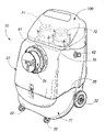
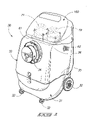
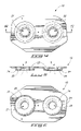
- FIG. 1 is a perspective, side elevation view of a floor cleaning device which incorporates features of the present invention.
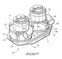
- FIG. 2 is a perspective, environmental view of a motor manifold of the present invention.
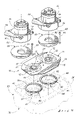
- FIG. 3 is a fragmentary, perspective, exploded view of a motor manifold of the present invention.
- FIG. 4 is a top plan view of a motor manifold of the present invention.
- FIG. 5 is a transverse, vertical, sectional view of a motor manifold of the present invention.
- FIG. 6 is a bottom plan view of the motor manifold of the present invention.
- the present invention relates to a motor manifold 10 which may be employed on a floor cleaning device which will be discussed in greater detail hereinafter.
- the motor manifold 10 is defined by a main body 11 , and which has an upwardly facing surface 12 , and an opposite downwardly facing surface 13 .
- the main body is defined by a peripheral edge 14 , and a plurality of fastener holes 15 are positioned in predetermined spaced relation about the main body and near the peripheral edge thereof.
- first and second apertures 21 and 22 respectively are formed in the main body 11 , and extend between the upwardly facing surface 12 , and the downwardly facing surface 13 .
- the first and second apertures each have a diameter of about 4.3 cm.
- an annularly shaped recessed region 23 is formed in the upwardly facing surface 12 , and substantially circumscribes the respective first and second apertures 21 and 22 , respectively.
- the annularly shaped recessed regions are operable to cooperate with a pair of gaskets or other sealing members which will be discussed in greater detail hereinafter.
- Extending normally, outwardly relative to the downwardly facing surface 13 are individually annularly shaped projections or male members which are generally indicated by the numeral 24 .
- the annularly shaped projections, or male members 24 substantially circumscribe the first and second apertures 21 and 22 , respectively.
- Each of the annularly shaped male members 24 have an outside facing surface 25 .
- the outside facing surface may, in one form of the invention, be a uniformly curved exterior facing surface, or further in another form of the invention, the annularly shaped male member may have a complexly curved exterior or outside facing surface 25 .
- the annularly shaped protruding or male members each extend outwardly relative to the downwardly facing surface 13 at a distance of less than about 1.25 cm. Still further, each has a width dimension of about 3.5 cm.
- the shape of the annularly shaped male members 24 is such as to provide a substantially uniform or laminar flow of air from a fluid recovery tank into an associated fan so as to improve the performance of an associated electrical motor by at least 3%.
- the electrical motor and associated fan assembly and other features of the invention will be discussed in greater detail below.
- the motor manifold 10 of the present invention finds usefulness when made integral with a floor cleaning device which is generally indicated by the numeral 30 .
- the floor cleaning device 30 includes a carriage 31 which has a plurality of wheels 32 mounted on same, and which allows the carriage to be rollably propelled across a supporting surface such as a floor, and the like.
- Mounted on the carriage 31 is a fluid recovery tank 33 .
- the fluid recovery tank 33 defines an internal cavity 34 for receiving various fluids which are removed from a floor by the floor cleaning device 30 , such as what is shown.
- the fluid recovery tank 33 has a first downwardly facing end 35 , which rests in engagement with the carriage 31 , and further has a second, upwardly facing end 36 , which is best seen by reference to FIG. 3 .
- the second, upwardly facing surface 36 defines a receiving or other orientation cavity 40 which is operable to matingly cooperate with the main body 11 which is received within the cavity 40 .
- a plurality of fastener holes 41 are formed in the fluid recovery tank 33 , and are otherwise operable to be substantially coaxially aligned relative to the multiplicity of fastener holes 15 which are formed in the main body 11 . As illustrated in FIG.
- first and second apertures 51 and 52 having an outside diametral dimension which is greater than the outside diametral dimension of the respective annularly shaped male members 24 are formed therein.
- the respective first and second apertures 51 and 52 are spaced apart at a predetermined distance such that the respective annularly shaped male members 24 may be received within same and extend, at least in part, into the internal cavity 34 of the fluid recovery tank 33 .
- first and second air movement or fan assemblies 61 and 62 Mounted in sealably secure relation, and in coaxial alignment, and further in fluid flow relation relative to the respective first and second apertures 51 and 52 are individual first and second air movement or fan assemblies 61 and 62 , respectively.
- the respective first and second air movement or fan assemblies 61 and 62 are, as seen, substantially coaxially oriented relative to the first and second apertures 21 and 22 which are formed in the main body 11 of the motor manifold, and are further secured to the motor manifold by a plurality of mounting bolts which will be discussed below.
- the respective air movement or fan assemblies 61 and 62 have an intake end 63 and an exhaust end 64 .
- the respective fan assemblies 61 and 62 when energized, are operable to remove air from the internal cavity 34 of the fluid recovery tank 33 thereby creating a vacuum in same. This vacuum is operable, in part, to remove fluid, foams or other materials from a surface being treated by a floor cleaning device 30 . As best seen by reference to FIG. 5 , the respective fan assemblies 61 and 62 , when energized, causes air to be removed in a substantially uniform, laminar flow which increases the performance of the accompanying first and second electric motors 71 and 72 by at least 3%. These electric engines are mounted in individual coaxial alignment relative to the first and second apertures 51 and 52 , and in force transmitting relation relative to the respective first and second air movement or fan assemblies 61 and 62 .
- the first and second electric motors in combination with the first and second air movement or fan assemblies 61 and 62 , are secured to the motor manifold 10 by a plurality of mounting bolts 73 which extend from the second upwardly facing end 36 of the fluid recovery tank 33 through the main body 11 of the motor manifold 10 , and which terminate at each of the first and second electric motors 71 and 72 .
- This is best appreciated and understood by a study of FIGS. 2 and 3 , respectively.
- a pair of gaskets 80 hereinafter indicated as a first and second gasket 81 and 82 , respectively, individually circumscribe the respective annularly shaped male protruding members 24 .
- These gaskets substantially sealably mates or secures the downwardly facing surface 13 of the main body 11 with the fluid recovery tank 33 .
- a second pair of gaskets 90 hereinafter indicated as a first gasket 91 , and a second gasket 92 , are received, at least in part, within the respective annularly shaped recessed regions 23 that are defined in the upwardly facing surface 12 of the main body 11 and which substantially sealably mates or otherwise secures the respective first and second air movement or fan assemblies 61 and 62 , and the first and second electric motor 71 and 72 to the upwardly facing surface 12 of the main body 11 .
- a closure or cover 100 is provided, and which encloses the motor manifold 10 ; first and second electric motors 71 and 72 ; and first and second air movement or fan assemblies 61 and 62 which are mounted on the motor manifold 10 .
- the motor manifold 10 of the present invention includes a main body 11 with an upwardly facing surface 12 which supports a motor 71 which drives an air movement assembly 61 ; and a downwardly facing surface 13 which rests in juxtaposed relation relative to a fluid recovery tank 33 , and wherein the main body 11 defines an aperture 21 which extends therethrough.
- the motor 71 and associated air movement assembly 61 are substantially aligned with the aperture 21 , and wherein the downwardly facing surface 13 defines an annularly shaped male member 24 which circumscribes the aperture 21 , and which is further matingly received, at least in part, within the fluid recovery tank 33 .
- the motor 71 , and associated air movement assembly 61 when energized, induces a flow of air from the fluid recovery tank 33 and through the air movement assembly 61 .
- the annularly shaped male member 24 creates a substantially uniform or laminar flow of air in the direction of the motor 71 .
- the annularly shaped male member 24 may, in one form of the invention, have a substantially uniformly curved exterior facing surface, and in another form of the invention have a complexly curved exterior facing surface 25 .
- the annularly shaped male member 24 improves the performance of the motor 71 by at least 3%.
- the fluid recovery tank 33 defines an aperture 51 having a given diameter.
- the annularly shaped male member 24 has an outside diameter which is less than the diameter of the aperture 51 defined by the fluid recovery tank 33 .
- a first gasket 81 is located between, and substantially sealably couples the downwardly facing surface 13 of the main body 11 with the fluid recovery tank 33 . This gasket further circumscribes the aperture 51 , which is defined by the fluid recovery tank 33 , and the annularly shaped male member 24 .
- a second gasket 91 is provided, and which is located between, and substantially sealably couples the upwardly facing surface of the main body 11 with the fan 61 and associated motor 71 . The second gasket 91 substantially circumscribes the aperture 51 which is defined by the main body 11 .
- the upwardly facing surface 12 of the main body 11 defines an annular shaped recessed region 23 which circumscribes the aperture 21 which is defined by the main body.
- the second gasket 91 is received, at least in part, within the annular shaped recessed region 23 .
- the main body 11 defines, in a preferred form, first and second apertures 21 and 22 , respectively.
- a pair of motors 71 and 72 are mounted on the upwardly facing surface 12 of the main body and are individually aligned with the respective apertures.
- a floor cleaning device 30 which supports a fluid recovery tank 33 for movement across a supporting surface such as a floor and the like.
- the fluid recovery tank 33 defines an internal cavity 34 , and further has a top or upwardly facing surface 36 , which defines an aperture 51 which allow access to the internal cavity 34 .
- a first gasket 81 circumscribes the aperture 51 which is defined by the top surface 36 of the fluid recovery tank 33 .
- a motor manifold 11 is provided and which has a downwardly facing surface 13 which defines, at least in part, an annularly shaped male member 24 which protrudes outwardly therefrom.
- the annularly shaped male member extends through the aperture 51 which is defined by the top surface 36 , and further is positioned, at least in part, within the internal cavity 34 of the fluid recovery tank 33 .
- the annularly shaped male member 24 circumscribes an aperture 21 which extends through the motor manifold 11 .
- the first gasket 81 substantially sealably couples the downwardly facing surface 13 of the motor manifold 11 with the top surface 36 of the fluid dispensing tank 33 .
- the motor manifold 11 has an opposite, upwardly facing surface 12 which defines an annularly shaped recessed region 23 which surrounds the aperture 21 .
- a second gasket 91 is received, at least in part, within the annular shaped recessed region 23 which is formed in the upwardly facing surface 12 of the motor manifold 10 .
- the present invention includes an electric motor 71 which is drivingly coupled with a fan 61 .
- the electric motor 71 is mounted on the upwardly facing surface 12 of the motor manifold 10 .
- the second gasket 91 is positioned in sealing relation between the electric motor 71 and the upwardly facing surface 12 .
- the electric motor 71 when energized, causes the fan 61 to withdraw air from the fluid recovery tank 33 , thereby creating a vacuum.
- the withdrawn air passes from the fluid recovery tank 33 through the aperture 21 defined by motor manifold 10 by the action of the fan 61 .
- the substantially uniform or laminar flow of the air from the fluid recovery tank increases the performance of the electric motor by at least 3%.
- This increase in the performance of the respective electric motor permits a manufacturer to utilize a larger fluid recovery tank.
- larger fluid recovery tanks directly translates into the production of a floor cleaning device 30 which has greatly improved operational times and performance.
- this increase in performance additionally allows a user of such a device to remove more fluids in a shorter period of time from a flooring surface.
- This increase in the removal of fluids directly translates into the removal of more dirt from the floor and/or quicker drying of the flooring surface. Both of which are highly desirable characteristics.
Landscapes
- Engineering & Computer Science (AREA)
- Mechanical Engineering (AREA)
- Cleaning By Liquid Or Steam (AREA)
Abstract
A motor manifold is disclosed and which includes a main body with an upwardly facing surface which supports a motor which drives an air movement assembly; and a downwardly facing surface which rests in juxtaposed relation relative to a fluid recovery tank, and wherein the main body defines an aperture which extends therethrough, and wherein the motor and associated air movement assembly are substantially aligned with the aperture, and wherein the downwardly facing surface defines an annularly shaped male member which circumscribes the aperture, and is matingly received within the fluid recovery tank.
Description
- The present invention relates to a motor manifold, and more specifically to a motor manifold which facilitates the smooth flow of air into an electrical engine so as to increase the performance characteristics of same.
- Assorted floor cleaning devices and apparatuses have been developed to facilitate the cleaning of floors in commercial establishments such as businesses, hotels, restaurants and the like. Such floor cleaning devices have included assemblies that have been useful for cleaning various surfaces such as carpet, tile, linoleum, brick, and ceramic surfaces to name but a few. Still further, other devices have been developed to facilitate the cleaning of structures that have been affected by flood, fire and the like.
- In all these previous devices, an electric motor is employed in order to facilitate the vacuum recovery of heated water, foaming agents, and other fluids which have been applied to a flooring surface to facilitate the cleaning of same. Such cleaning devices have typically been limited in their capacity to hold recovered fluids. This is due, in part, to the size of the tank, as dictated by the size of the electric motor which is employed with same. It should be recognized that the size of such motors are limited because such devices are typically employed in commercial buildings where electrical power is typically limited to 120 volts, 15 amp power sources. In view of the amount of vacuum, such devices can reasonably draw or create within, a typical recovery tank, the associated fluid recovery tanks have remained relatively small in size. Consequently, the prior art devices can only be operated for short periods of time before an operator must stop the device and thereafter empty the fluid recovery tank before proceeding with further work. Additionally, this reduced vacuum translates into lower fluid recovery, and less soil removal from the floor which is being treated. Consequently, a greater period of time, and work must be undertaken to clean a given flooring surface.
- Therefore, it would be desirable to provide a floor cleaning device which could, on the one hand, clean flooring surfaces in a highly efficient manner, and utilize a larger fluid recovery tank which would facilitate increased operational times but which would employ an electrical motor not requiring a special power source to facilitate the effective operation of same.
- A motor manifold which achieves the benefits of the present invention will be described in greater detail hereinafter.
- A first aspect of the present invention relates to a motor manifold which includes a main body with an upwardly facing surface which supports a motor which drives an air movement assembly; and a downwardly facing surface which rests in juxtaposed relation relative to a fluid recovery tank, and wherein the main body defines an aperture which extends therethrough, and wherein the motor and associated air movement assembly are substantially aligned with the aperture, and wherein the downwardly facing surface defines an annular shaped male member which circumscribes the aperture, and is matingly received within the fluid recovery tank.
- Another aspect of the present invention relates to a motor manifold which includes a main body with an upwardly and a downwardly facing surface, and wherein the downwardly facing surface matingly engages a fluid recovery tank of a floor cleaning device, and wherein the fluid recovery tank defines two apertures which allows access to the fluid recovery tank, and wherein the main body further defines a pair of apertures which extend between the upwardly and downwardly facing surfaces thereof, and wherein the pair of apertures defined by the main body are substantially coaxially aligned relative to the two apertures defined by the fluid recovery tank, and in fluid flowing relation relative thereto, and wherein the upwardly facing surface defines a pair of annular shaped recessed regions which individually surround the pair of apertures which are defined by the main body, and wherein the downwardly facing surface defines a pair of annularly shaped protruding members which individually circumscribe the respective pair of apertures which are defined by the main body, and which are individually, matingly received within the two apertures which are defined by the fluid recovery tank, and wherein a pair of electric motors are individually mounted on the upwardly facing surface of the main body and are substantially coaxially aligned relative to the pair of apertures as defined by the main body.
- Still another aspect of the present invention relates to a floor cleaning device which includes a carriage having wheels and which supports a fluid recovery tank for movement across a supporting surface, and wherein the fluid recovery tank defines an internal cavity and further has a top surface which defines an aperture which allows access to the internal cavity; a first gasket which circumscribes the aperture which is defined by the top surface of the fluid recovery tank; a motor manifold having a downwardly facing surface which defines, at least in part, an annularly shaped male member which protrudes outwardly therefrom, and which extends through the aperture defined by the top surface of the fluid recovery tank, and which is further positioned, at least in part, within the internal cavity of the fluid recovery tank, and wherein the annularly shaped male member circumscribes an aperture which extends through the motor manifold, and wherein the first gasket substantially sealably couples the downwardly facing surface of the motor manifold with the top surface of the fluid dispensing tank, and wherein the motor manifold has an opposite, upwardly facing surface which defines an annular shaped recessed region which surrounds the aperture which extends through the motor manifold; a second gasket received at least in part within the annular shaped recessed region formed in the upwardly facing surface of the motor manifold; and an electric motor which is drivingly coupled with a fan, and wherein the electric motor is mounted on the upwardly facing surface of the motor manifold, and wherein the second gasket is positioned in sealing relation between the electric motor and the upwardly facing surface, and wherein the electric motor, when energized causes the fan to withdraw air from the fluid recovery tank, and wherein the withdrawn air passes from the fluid recovery tank through the aperture defined by motor manifold by the action of the fan.
- These and other aspects of the present invention will be described in greater detail hereinafter.
- Preferred embodiments of the invention are described below with reference to the following accompanying drawings.
-
FIG. 1 is a perspective, side elevation view of a floor cleaning device which incorporates features of the present invention. -
FIG. 2 is a perspective, environmental view of a motor manifold of the present invention. -
FIG. 3 is a fragmentary, perspective, exploded view of a motor manifold of the present invention. -
FIG. 4 is a top plan view of a motor manifold of the present invention. -
FIG. 5 is a transverse, vertical, sectional view of a motor manifold of the present invention. -
FIG. 6 is a bottom plan view of the motor manifold of the present invention. - This disclosure of the invention is submitted in furtherance of the constitutional purposes of the U.S. Patent Laws “to promote the progress of science and useful arts” (Article 1, Section 8).
- The present invention relates to a
motor manifold 10 which may be employed on a floor cleaning device which will be discussed in greater detail hereinafter. In this regard, themotor manifold 10 is defined by amain body 11, and which has an upwardly facingsurface 12, and an opposite downwardly facingsurface 13. As seen most clearly by reference toFIGS. 3-6 , the main body is defined by aperipheral edge 14, and a plurality offastener holes 15 are positioned in predetermined spaced relation about the main body and near the peripheral edge thereof. As illustrated inFIGS. 3-6 , first andsecond apertures main body 11, and extend between the upwardly facingsurface 12, and the downwardly facingsurface 13. The first and second apertures each have a diameter of about 4.3 cm. As illustrated most clearly by reference toFIG. 3 , an annularly shapedrecessed region 23 is formed in the upwardly facingsurface 12, and substantially circumscribes the respective first andsecond apertures surface 13, are individually annularly shaped projections or male members which are generally indicated by thenumeral 24. The annularly shaped projections, ormale members 24 substantially circumscribe the first andsecond apertures male members 24 have an outside facingsurface 25. The outside facing surface may, in one form of the invention, be a uniformly curved exterior facing surface, or further in another form of the invention, the annularly shaped male member may have a complexly curved exterior or outside facingsurface 25. The annularly shaped protruding or male members each extend outwardly relative to the downwardly facingsurface 13 at a distance of less than about 1.25 cm. Still further, each has a width dimension of about 3.5 cm. The shape of the annularlyshaped male members 24 is such as to provide a substantially uniform or laminar flow of air from a fluid recovery tank into an associated fan so as to improve the performance of an associated electrical motor by at least 3%. The electrical motor and associated fan assembly and other features of the invention will be discussed in greater detail below. - Referring now to
FIGS. 1 and 3 , it will be seen that themotor manifold 10 of the present invention finds usefulness when made integral with a floor cleaning device which is generally indicated by thenumeral 30. Thefloor cleaning device 30, as seen in the drawings, includes acarriage 31 which has a plurality ofwheels 32 mounted on same, and which allows the carriage to be rollably propelled across a supporting surface such as a floor, and the like. Mounted on thecarriage 31 is afluid recovery tank 33. Thefluid recovery tank 33 defines aninternal cavity 34 for receiving various fluids which are removed from a floor by thefloor cleaning device 30, such as what is shown. Thefluid recovery tank 33 has a first downwardly facingend 35, which rests in engagement with thecarriage 31, and further has a second, upwardly facingend 36, which is best seen by reference toFIG. 3 . The second, upwardly facingsurface 36 defines a receiving orother orientation cavity 40 which is operable to matingly cooperate with themain body 11 which is received within thecavity 40. As illustrated inFIG. 3 , a plurality offastener holes 41 are formed in thefluid recovery tank 33, and are otherwise operable to be substantially coaxially aligned relative to the multiplicity offastener holes 15 which are formed in themain body 11. As illustrated inFIG. 3 , first andsecond apertures male members 24 are formed therein. The respective first andsecond apertures male members 24 may be received within same and extend, at least in part, into theinternal cavity 34 of thefluid recovery tank 33. - Mounted in sealably secure relation, and in coaxial alignment, and further in fluid flow relation relative to the respective first and
second apertures fan assemblies fan assemblies second apertures main body 11 of the motor manifold, and are further secured to the motor manifold by a plurality of mounting bolts which will be discussed below. The respective air movement or fan assemblies 61 and 62 have anintake end 63 and anexhaust end 64. The respective fan assemblies 61 and 62, when energized, are operable to remove air from theinternal cavity 34 of thefluid recovery tank 33 thereby creating a vacuum in same. This vacuum is operable, in part, to remove fluid, foams or other materials from a surface being treated by afloor cleaning device 30. As best seen by reference toFIG. 5 , the respective fan assemblies 61 and 62, when energized, causes air to be removed in a substantially uniform, laminar flow which increases the performance of the accompanying first and secondelectric motors second apertures fan assemblies fan assemblies motor manifold 10 by a plurality ofmounting bolts 73 which extend from the second upwardly facingend 36 of thefluid recovery tank 33 through themain body 11 of themotor manifold 10, and which terminate at each of the first and secondelectric motors FIGS. 2 and 3 , respectively. - As best illustrated in
FIG. 3 , it will be seen that a pair ofgaskets 80, hereinafter indicated as a first andsecond gasket members 24. These gaskets substantially sealably mates or secures the downwardly facingsurface 13 of themain body 11 with thefluid recovery tank 33. Still further, a second pair ofgaskets 90, hereinafter indicated as afirst gasket 91, and asecond gasket 92, are received, at least in part, within the respective annularly shaped recessedregions 23 that are defined in the upwardly facingsurface 12 of themain body 11 and which substantially sealably mates or otherwise secures the respective first and second air movement orfan assemblies electric motor surface 12 of themain body 11. - Referring now to
FIG. 1 , it will be seen that a closure or cover 100 is provided, and which encloses themotor manifold 10; first and secondelectric motors fan assemblies motor manifold 10. - The operation of the described embodiment of the present invention is believed to be readily apparent and is briefly summarized at this point.
- Referring now to the drawings, the
motor manifold 10 of the present invention includes amain body 11 with an upwardly facingsurface 12 which supports amotor 71 which drives anair movement assembly 61; and a downwardly facingsurface 13 which rests in juxtaposed relation relative to afluid recovery tank 33, and wherein themain body 11 defines anaperture 21 which extends therethrough. Themotor 71 and associatedair movement assembly 61 are substantially aligned with theaperture 21, and wherein the downwardly facingsurface 13 defines an annularly shapedmale member 24 which circumscribes theaperture 21, and which is further matingly received, at least in part, within thefluid recovery tank 33. Themotor 71, and associatedair movement assembly 61, when energized, induces a flow of air from thefluid recovery tank 33 and through theair movement assembly 61. The annularly shapedmale member 24 creates a substantially uniform or laminar flow of air in the direction of themotor 71. As earlier described, the annularly shapedmale member 24 may, in one form of the invention, have a substantially uniformly curved exterior facing surface, and in another form of the invention have a complexly curvedexterior facing surface 25. In the arrangement as seen in the drawings, the annularly shapedmale member 24 improves the performance of themotor 71 by at least 3%. It should be understood that thefluid recovery tank 33 defines anaperture 51 having a given diameter. Still further, the annularly shapedmale member 24 has an outside diameter which is less than the diameter of theaperture 51 defined by thefluid recovery tank 33. In the arrangement as seen in the drawings, afirst gasket 81 is located between, and substantially sealably couples the downwardly facingsurface 13 of themain body 11 with thefluid recovery tank 33. This gasket further circumscribes theaperture 51, which is defined by thefluid recovery tank 33, and the annularly shapedmale member 24. In the arrangement as seen in the drawings, asecond gasket 91 is provided, and which is located between, and substantially sealably couples the upwardly facing surface of themain body 11 with thefan 61 and associatedmotor 71. Thesecond gasket 91 substantially circumscribes theaperture 51 which is defined by themain body 11. In the arrangement as seen in the drawings, the upwardly facingsurface 12 of themain body 11 defines an annular shaped recessedregion 23 which circumscribes theaperture 21 which is defined by the main body. As illustrated, thesecond gasket 91 is received, at least in part, within the annular shaped recessedregion 23. In addition to the foregoing, themain body 11 defines, in a preferred form, first andsecond apertures motors surface 12 of the main body and are individually aligned with the respective apertures. - With reference to
FIG. 1 now, afloor cleaning device 30 is shown and which supports afluid recovery tank 33 for movement across a supporting surface such as a floor and the like. Thefluid recovery tank 33 defines aninternal cavity 34, and further has a top or upwardly facingsurface 36, which defines anaperture 51 which allow access to theinternal cavity 34. As seen in the drawings, afirst gasket 81 circumscribes theaperture 51 which is defined by thetop surface 36 of thefluid recovery tank 33. Still further, amotor manifold 11 is provided and which has a downwardly facingsurface 13 which defines, at least in part, an annularly shapedmale member 24 which protrudes outwardly therefrom. The annularly shaped male member extends through theaperture 51 which is defined by thetop surface 36, and further is positioned, at least in part, within theinternal cavity 34 of thefluid recovery tank 33. The annularly shapedmale member 24 circumscribes anaperture 21 which extends through themotor manifold 11. Thefirst gasket 81 substantially sealably couples the downwardly facingsurface 13 of themotor manifold 11 with thetop surface 36 of thefluid dispensing tank 33. Themotor manifold 11 has an opposite, upwardly facingsurface 12 which defines an annularly shaped recessedregion 23 which surrounds theaperture 21. Asecond gasket 91 is received, at least in part, within the annular shaped recessedregion 23 which is formed in the upwardly facingsurface 12 of themotor manifold 10. Further, the present invention includes anelectric motor 71 which is drivingly coupled with afan 61. In the arrangement as seen in the drawings, theelectric motor 71 is mounted on the upwardly facingsurface 12 of themotor manifold 10. Thesecond gasket 91 is positioned in sealing relation between theelectric motor 71 and the upwardly facingsurface 12. In the arrangement as illustrated, theelectric motor 71, when energized, causes thefan 61 to withdraw air from thefluid recovery tank 33, thereby creating a vacuum. The withdrawn air passes from thefluid recovery tank 33 through theaperture 21 defined bymotor manifold 10 by the action of thefan 61. The substantially uniform or laminar flow of the air from the fluid recovery tank increases the performance of the electric motor by at least 3%. This increase in the performance of the respective electric motor permits a manufacturer to utilize a larger fluid recovery tank. As should be understood, larger fluid recovery tanks directly translates into the production of afloor cleaning device 30 which has greatly improved operational times and performance. Still further, this increase in performance additionally allows a user of such a device to remove more fluids in a shorter period of time from a flooring surface. This increase in the removal of fluids directly translates into the removal of more dirt from the floor and/or quicker drying of the flooring surface. Both of which are highly desirable characteristics. - Therefore, it will be seen that a motor manifold, and a
floor cleaning device 30 which incorporates such a manifold has numerous advantages over the prior art devices which have been utilized heretofore. - In compliance with the statute, the invention has been described in language more or less specific as to structural and methodical features. It is to be understood, however, that the invention is not limited to the specific features shown and described, since the means herein disclosed comprise preferred forms of putting the invention into effect. The invention is, therefore, claimed in any of its forms or modifications within the proper scope of the appended claims appropriately interpreted in accordance with the doctrine of equivalents.
Claims (16)
1. A motor manifold, comprising:
a main body with an upwardly facing surface which supports a motor which drives an air movement assembly; and a downwardly facing surface which rests in juxtaposed relation relative to a fluid recovery tank, and wherein the main body defines an aperture which extends therethrough, and wherein the motor and associated air movement assembly are substantially aligned with the aperture, and wherein the downwardly facing surface defines an annularly shaped male member which circumscribes the aperture, and is matingly received within the fluid recovery tank.
2. A motor manifold as claimed in claim 1 , and wherein the motor and associated air movement assembly, when energized, induces a flow of air from the fluid recovery tank and through the air movement assembly, and wherein the annularly shaped male member creates a substantially uniform flow of air into the motor.
3. A motor manifold as claimed in claim 1 , and wherein the annularly shaped male member has a substantially uniformly curved exterior facing surface.
4. A motor manifold as claimed in claim 1 , and wherein the annularly shaped male member has a complexly curved exterior facing surface.
5. A motor manifold as claimed in claim 1 , and wherein the annularly shaped male member improves the performance of the motor by at least 3%.
6. A motor manifold as claimed in claim 1 , and wherein the fluid recovery tank defines an aperture having a given diameter, and wherein the annularly shaped male member has an outside diameter which is less than the diameter of the aperture defined by the fluid recovery tank.
7. A motor manifold as claimed in claim 6 , and further comprising:
a first gasket which is located between and substantially sealably couples the downwardly facing surface of the main body with the fluid recovery tank, and which further circumscribes the aperture which is defined by the fluid recovery tank and the annularly shaped male member.
8. A motor manifold a claimed in claim 7 , and further comprising:
a second gasket which is located between, and substantially sealably couples the upwardly facing surface of the main body with the motor, and wherein the second gasket substantially circumscribes the aperture which is defined by the main body.
9. An engine manifold as claimed in claim 8 , and wherein the upwardly facing surface of the main body defines an annular shaped recessed region which circumscribes the aperture which is defined by the main body, and wherein the second gasket is received, at least in part, within the recessed region.
10. An engine manifold as claimed in claim 1 , and wherein the main body defines a pair of spaced apertures, and wherein a pair of motors are mounted on the upwardly facing surface of the main body and are individually aligned with the respective apertures.
11. A motor manifold, comprising:
a main body with an upwardly and a downwardly facing surface, and wherein the downwardly facing surface matingly engages a fluid recovery tank of a floor cleaning device, and wherein the fluid recovery tank defines two apertures which allows access to the fluid recovery tank, and wherein the main body further defines a pair of apertures which extend between the upwardly and downwardly facing surfaces thereof, and wherein the pair of apertures defined by the main body are substantially coaxially aligned relative to the two apertures defined by the fluid recovery tank, and in fluid flowing relation relative thereto, and wherein the upwardly facing surface defines a pair of annular shaped recessed regions which individually surround the pair of apertures which are defined by the main body, and wherein the downwardly facing surface defines a pair of annularly shaped protruding members which individually circumscribe the respective pair of apertures which are defined by the main body, and which are individually, matingly received within the two apertures which are defined by the fluid recovery tank, and wherein a pair of electric motors are individually mounted on the upwardly facing surface of the main body and are substantially coaxially aligned relative to the pair of apertures as defined by the main body.
12. A motor manifold as claimed in claim 11 , and wherein a fan is mounted on each of the electric motors, and is driven by the respective electric motors, and wherein each of the fans, when driven by the respective electric motors removes air from within the fluid recovery tank, and wherein the annularly shaped protruding members each causes air to flow from the fluid recovery tank into the respective pair of electric motors in a substantially laminar fashion so as to increase the performance of the respective electric motors by at least 3%.
13. A motor manifold as claimed in claim 11 , and wherein the pair of apertures defined by the main body each has a diameter of about 4.3 cm., and wherein the annular shaped protruding members each extend less than about 1.25 cm. into the fluid recovery tank.
14. A motor manifold as claimed in claim 11 , and further comprising:
a first pair of gaskets which individually circumscribe the respective annularly shaped protruding members and which substantially sealably mates the downwardly facing surface of the main body with the fluid recovery tank; and
a second pair of gaskets which are received, at least in part, within the respective annular shaped recessed regions that are defined in the upwardly facing surface of the main body and which substantially sealably mates the respective electric motors to the upwardly facing surface of the main body.
15. A floor cleaning device, comprising:
a carriage having wheels and which supports a fluid recovery tank for movement across a supporting surface, and wherein the fluid recovery tank defines an internal cavity and further has a top surface which defines an aperture which allows access to the internal cavity;
a first gasket which circumscribes the aperture which is defined by the top surface of the fluid recovery tank;
a motor manifold having a downwardly facing surface which defines, at least in part, an annularly shaped male member which protrudes outwardly therefrom, and which extends through the aperture defined by the top surface of the fluid recovery tank, and which is further positioned, at least in part, within the internal cavity of the fluid recovery tank, and wherein the annularly shaped male member circumscribes an aperture which extends through the motor manifold, and wherein the first gasket substantially sealably couples the downwardly facing surface of the motor manifold with the top surface of the fluid dispensing tank, and wherein the motor manifold has an opposite, upwardly facing surface which defines an annular shaped recessed region which surrounds the aperture which extends through the motor manifold;
a second gasket received, at least in part, within the annular shaped recessed region formed in the upwardly facing surface of the motor manifold; and
an electric motor which is drivingly coupled with a fan, and wherein the electric motor is mounted on the upwardly facing surface of the motor manifold, and wherein the second gasket is positioned in sealing relation between the electric motor and the upwardly facing surface, and wherein the electric motor, when energized, causes the fan to withdraw air from the fluid recovery tank, and wherein the withdrawn air passes from the fluid recovery tank through the aperture defined by the motor manifold by the action of the fan.
16. A floor cleaning device as claimed in claim 15 , and wherein the annularly shaped male member has a curved exterior facing surface which facilitates substantially laminar air flow from the internal cavity of the fluid recovery tank to the electric motor to improve the performance thereof.
Priority Applications (1)
| Application Number | Priority Date | Filing Date | Title |
|---|---|---|---|
| US11/591,959 US20080098560A1 (en) | 2006-11-01 | 2006-11-01 | Motor manifold |
Applications Claiming Priority (1)
| Application Number | Priority Date | Filing Date | Title |
|---|---|---|---|
| US11/591,959 US20080098560A1 (en) | 2006-11-01 | 2006-11-01 | Motor manifold |
Publications (1)
| Publication Number | Publication Date |
|---|---|
| US20080098560A1 true US20080098560A1 (en) | 2008-05-01 |
Family
ID=39328412
Family Applications (1)
| Application Number | Title | Priority Date | Filing Date |
|---|---|---|---|
| US11/591,959 Abandoned US20080098560A1 (en) | 2006-11-01 | 2006-11-01 | Motor manifold |
Country Status (1)
| Country | Link |
|---|---|
| US (1) | US20080098560A1 (en) |
Cited By (2)
| Publication number | Priority date | Publication date | Assignee | Title |
|---|---|---|---|---|
| US20130111697A1 (en) * | 2011-11-08 | 2013-05-09 | Nilfisk-Advance, Inc. | Portable extractor machine |
| USD792570S1 (en) * | 2015-04-15 | 2017-07-18 | K&N Engineering, Inc. | Vent breather |
Citations (2)
| Publication number | Priority date | Publication date | Assignee | Title |
|---|---|---|---|---|
| US3848290A (en) * | 1971-12-27 | 1974-11-19 | C Bates | Rinse method and machine |
| US7461430B2 (en) * | 2005-01-10 | 2008-12-09 | Broan-Nutone Llc | Vacuum system and method |
-
2006
- 2006-11-01 US US11/591,959 patent/US20080098560A1/en not_active Abandoned
Patent Citations (2)
| Publication number | Priority date | Publication date | Assignee | Title |
|---|---|---|---|---|
| US3848290A (en) * | 1971-12-27 | 1974-11-19 | C Bates | Rinse method and machine |
| US7461430B2 (en) * | 2005-01-10 | 2008-12-09 | Broan-Nutone Llc | Vacuum system and method |
Cited By (3)
| Publication number | Priority date | Publication date | Assignee | Title |
|---|---|---|---|---|
| US20130111697A1 (en) * | 2011-11-08 | 2013-05-09 | Nilfisk-Advance, Inc. | Portable extractor machine |
| US10426304B2 (en) * | 2011-11-08 | 2019-10-01 | Hydramaster, Llc | Portable extractor machine |
| USD792570S1 (en) * | 2015-04-15 | 2017-07-18 | K&N Engineering, Inc. | Vent breather |
Similar Documents
| Publication | Publication Date | Title |
|---|---|---|
| KR100683074B1 (en) | robotic vacuum | |
| RU2251958C2 (en) | Robot vacuum cleaner making disturbance due to air | |
| JP5269958B2 (en) | Surface treatment robot | |
| RU2345699C2 (en) | Vacuum cleaner and method of its control | |
| US9038236B2 (en) | Filter shaker | |
| MXPA03003043A (en) | Edge cleaning system for vacuum cleaner. | |
| AU2003242697A1 (en) | Method for operating a floor cleaning system, and floor cleaning system associated with said method | |
| JP2016195886A (en) | Cleaning robot | |
| ATE376797T1 (en) | SUCTION UNIT WITH MULTIPLE SUCTION MOTORS | |
| US20080098560A1 (en) | Motor manifold | |
| US20160120385A1 (en) | Surface maintenance vehicle with an integrated water trap for trapping residual waste | |
| US20100170059A1 (en) | Vacuum cleaner attachment | |
| CN203701219U (en) | Multifunctional washing basin | |
| CN103726549A (en) | Multifunctional washing basin | |
| CN210262882U (en) | Road cleaning vehicle | |
| JP4823958B2 (en) | Drip / outflow prevention device for cleaning water in floor cleaning machine | |
| MXPA03003848A (en) | Edge cleaning apparatus for a vacuum cleaner. | |
| JP4614178B1 (en) | Nozzle for electric vacuum cleaner | |
| ITMI20031998A1 (en) | WASHING TANK IN PARTICULAR FOR BRAKES OF INDUSTRIAL AND SIMILAR VEHICLES | |
| CN111692689A (en) | Humidifier | |
| CN214511030U (en) | Toilet's ground processing apparatus | |
| CN217244158U (en) | Cleaning machine and clean water tank device for cleaning machine | |
| KR0152635B1 (en) | Vacuum cleaner of vehicle using negative pressure of engine | |
| CN218304728U (en) | Cleaning machine | |
| JPS6432097U (en) |
Legal Events
| Date | Code | Title | Description |
|---|---|---|---|
| AS | Assignment |
Owner name: U.S. PRODUCTS, IDAHO Free format text: ASSIGNMENT OF ASSIGNORS INTEREST;ASSIGNORS:WILLIAMS, STEVE;LLOYD, GREG;REEL/FRAME:018503/0154 Effective date: 20061031 |
|
| AS | Assignment |
Owner name: USP HOLDING CORP., MINNESOTA Free format text: ASSIGNMENT OF ASSIGNORS INTEREST;ASSIGNOR:PALOUSE HOLDINGS, LLC, D/B/A/ U.S. PRODUCTS, INC.;REEL/FRAME:018720/0194 Effective date: 20070101 |
|
| STCB | Information on status: application discontinuation |
Free format text: ABANDONED -- FAILURE TO RESPOND TO AN OFFICE ACTION |