US20080098557A1 - Wiper arm assembly having a locking surfaces and method of construction - Google Patents
Wiper arm assembly having a locking surfaces and method of construction Download PDFInfo
- Publication number
- US20080098557A1 US20080098557A1 US11/926,344 US92634407A US2008098557A1 US 20080098557 A1 US20080098557 A1 US 20080098557A1 US 92634407 A US92634407 A US 92634407A US 2008098557 A1 US2008098557 A1 US 2008098557A1
- Authority
- US
- United States
- Prior art keywords
- wiper arm
- mounting head
- extending
- sidewalls
- locking
- Prior art date
- Legal status (The legal status is an assumption and is not a legal conclusion. Google has not performed a legal analysis and makes no representation as to the accuracy of the status listed.)
- Granted
Links
Images

Classifications
-
- B—PERFORMING OPERATIONS; TRANSPORTING
- B60—VEHICLES IN GENERAL
- B60S—SERVICING, CLEANING, REPAIRING, SUPPORTING, LIFTING, OR MANOEUVRING OF VEHICLES, NOT OTHERWISE PROVIDED FOR
- B60S1/00—Cleaning of vehicles
- B60S1/02—Cleaning windscreens, windows or optical devices
- B60S1/04—Wipers or the like, e.g. scrapers
- B60S1/32—Wipers or the like, e.g. scrapers characterised by constructional features of wiper blade arms or blades
- B60S1/34—Wiper arms; Mountings therefor
- B60S1/3425—Constructional aspects of the arm
- B60S1/3445—Joints between elements
- B60S1/345—Joints between elements the elements being a link piece and a mounting head
- B60S1/3452—Joints between elements the elements being a link piece and a mounting head the joint being a snap fit pivot joint
-
- B—PERFORMING OPERATIONS; TRANSPORTING
- B60—VEHICLES IN GENERAL
- B60S—SERVICING, CLEANING, REPAIRING, SUPPORTING, LIFTING, OR MANOEUVRING OF VEHICLES, NOT OTHERWISE PROVIDED FOR
- B60S1/00—Cleaning of vehicles
- B60S1/02—Cleaning windscreens, windows or optical devices
- B60S1/04—Wipers or the like, e.g. scrapers
- B60S1/32—Wipers or the like, e.g. scrapers characterised by constructional features of wiper blade arms or blades
- B60S1/34—Wiper arms; Mountings therefor
- B60S1/3425—Constructional aspects of the arm
- B60S1/3431—Link pieces
-
- B—PERFORMING OPERATIONS; TRANSPORTING
- B60—VEHICLES IN GENERAL
- B60S—SERVICING, CLEANING, REPAIRING, SUPPORTING, LIFTING, OR MANOEUVRING OF VEHICLES, NOT OTHERWISE PROVIDED FOR
- B60S1/00—Cleaning of vehicles
- B60S1/02—Cleaning windscreens, windows or optical devices
- B60S1/04—Wipers or the like, e.g. scrapers
- B60S1/32—Wipers or the like, e.g. scrapers characterised by constructional features of wiper blade arms or blades
- B60S1/34—Wiper arms; Mountings therefor
- B60S1/3425—Constructional aspects of the arm
- B60S1/3436—Mounting heads
-
- B—PERFORMING OPERATIONS; TRANSPORTING
- B60—VEHICLES IN GENERAL
- B60S—SERVICING, CLEANING, REPAIRING, SUPPORTING, LIFTING, OR MANOEUVRING OF VEHICLES, NOT OTHERWISE PROVIDED FOR
- B60S1/00—Cleaning of vehicles
- B60S1/02—Cleaning windscreens, windows or optical devices
- B60S1/04—Wipers or the like, e.g. scrapers
- B60S1/32—Wipers or the like, e.g. scrapers characterised by constructional features of wiper blade arms or blades
- B60S1/34—Wiper arms; Mountings therefor
- B60S1/3463—Means to press blade onto screen
- B60S1/3465—Means to press blade onto screen with coil springs
-
- Y—GENERAL TAGGING OF NEW TECHNOLOGICAL DEVELOPMENTS; GENERAL TAGGING OF CROSS-SECTIONAL TECHNOLOGIES SPANNING OVER SEVERAL SECTIONS OF THE IPC; TECHNICAL SUBJECTS COVERED BY FORMER USPC CROSS-REFERENCE ART COLLECTIONS [XRACs] AND DIGESTS
- Y10—TECHNICAL SUBJECTS COVERED BY FORMER USPC
- Y10T—TECHNICAL SUBJECTS COVERED BY FORMER US CLASSIFICATION
- Y10T29/00—Metal working
- Y10T29/49—Method of mechanical manufacture
- Y10T29/49826—Assembling or joining
Definitions
- This invention relates generally to wiper arm assemblies for vehicles, and more particularly to wiper arm assemblies having a mounting head for attachment to a vehicle and a wiper arm attached for articulation relative to the mounting head, and methods of assembly thereof.
- Wiper arm assemblies for vehicles are known to have a wiper arm hinged for articulation relative to a mounting head.
- the mounting head facilitates attachment of the assembly to a surface on the vehicle so that a wiper blade attached to the wiper arm is suitably positioned for oscillation against a window.
- the wiper arm and wiper blade attached thereto can generally be articulated relative to the mounting head away from the window to a service-up position to facilitate replacing the wiper blade.
- the spring also allows the wiper arm to be articulated away from the window by manually lifting the wiper arm, such that the wiper blade can be serviced, as necessary. Though this type of wiper arm assembly works well in use, it typically comes with increased cost in manufacturing and assembly due to the added cost associated with the pin or rivet and the processes for permanently fixing the mounting head and wiper arm together.
- wiper arm assemblies with the mounting head and wiper arm attached to one another such that they can be disassembled from one another after being assembled in a “preassembled” position.
- a preassembled position is defined when the mounting head and wiper arm are attached together, but not yet assembled to a vehicle.
- the mounting head and wiper arm are attached together under a preload of a tension spring, with an axle on one of the parts being received to form a hinged connection in an open hub of the other part. Bearing surfaces on the mounting head and wiper arm are pulled into engagement with one another along a line of force imparted by the tension spring.
- the opposing reaction forces between the bearing surfaces act to maintain the mounting head and wiper arm in the preassembled position until the wiper arm assembly is fully assembled to a vehicle.
- the bearing surfaces are not prevented from moving back toward a disassembled direction and can slide relative to one another under a minimal force, which can occur during transport or during careless handling, whereupon the mounting head and wiper arm can become inadvertently disassembled.
- the '608 patent teaches forming the bearing surfaces as being arranged to define interacting camming surfaces.
- the bearing surfaces require the spring attaching the mounting head and the wiper arm to be increased in length, thus requiring an increased tensile force to be overcome prior to the parts becoming disassembled from one another.
- the '608 patent teaches that the mounting head can still be disassembled from the wiper arm by rotating the wiper arm relative to the mounting head toward the disassembled direction with a sufficient torque to overcome the cam lobe.
- a wiper arm assembly includes a mounting head having a first end with a bottom surface configured for mounting to a vehicle and a pair of laterally spaced sidewalls extending upwardly from the bottom surface to a second end with an axle extending between the sidewalls.
- the mounting head has a locking surface extending generally perpendicular to the bottom surface.
- a wiper arm extends along a longitudinal axis between a first end configured for operable attachment to a wiper blade and a second end having a hub with a pocket extending from an open end for receipt of the axle to a seating surface.
- the second end of the wiper arm has a protrusion extending outwardly in a direction generally opposite the first end of the wiper arm.
- the protrusion has a locking surface extending in a plane generally perpendicular to the longitudinal axis.
- a spring is arranged for operable attachment to the mounting head and the wiper arm.
- the locking surfaces of the mounting head and the wiper arm are configured to be brought into engagement with one another in a shipping position under a force imparted by the spring upon rotating the mounting head relative to the wiper arm from a disassembled position toward the shipping position.
- the locking surfaces confront each other in a plane generally perpendicular to the longitudinal axis while in the shipping position and prevent the mounting head and the wiper arm from rotating back toward the disassembled position from the shipping position.
- Another aspect of the invention provides a method of constructing a wiper arm assembly.
- the method starts with providing a mounting head having a bottom surface for mounting to a vehicle with a locking surface extending generally perpendicular to the bottom surface and having a pair of laterally spaced sidewalls with an axle extending between the sidewalls. Further, providing a wiper arm having a longitudinal axis extending between a first end and a second end. The second end is provided having a hub with a pocket and a protrusion extending outwardly opposite the first end. The protrusion is provided having a locking surface extending in a plane generally perpendicular to the longitudinal axis.
- a wiper arm assembly constructed in accordance with the invention provides a wiper arm assembly that is easy to assemble, economical in manufacture, prevented from becoming inadvertently disassembled, and has a long and useful life.
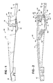
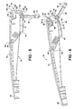
- FIG. 1 is a side view of a wiper arm assembly constructed in accordance with one presently preferred embodiment of the invention shown in a shipping position;
- FIG. 2 is a cross-sectional view taken generally along a central axis of the wiper arm assembly of FIG. 1 ;
- FIG. 3 is a enlarged partial view of FIG. 2 with a portion of a spring removed;
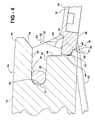
- FIG. 4 is a view similar to FIG. 3 showing a cross-section of the assembly along a line offset from the central axis;
- FIG. 5 is a view similar to FIG. 2 while in a disassembled position
- FIG. 6 is a view similar to FIG. 2 while in a partially assembled position
- FIG. 7 is a view similar to FIG. 2 while in a service-up position
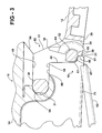
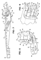
- FIG. 8 is a perspective view of a mounting head of the wiper arm assembly
- FIG. 9 is partial perspective view of a wiper arm of the wiper arm assembly
- FIG. 10 is a partial cross-sectional view of a wiper arm assembly constructed in accordance with another embodiment of the invention.
- FIG. 11 is a partial cross-sectional view of a wiper arm assembly constructed in accordance with yet another embodiment of the invention.
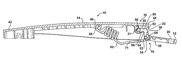
- FIGS. 1-2 and 5 - 7 show a wiper arm assembly 10 constructed according to one presently preferred embodiment of the invention.
- the wiper arm assembly 10 has a mounting head 12 to facilitate attachment of the assembly 10 to a vehicle, and a wiper arm 14 for operable attachment of a wiper blade (not shown) to the assembly 10 .
- the wiper arm 14 is attached for articulated movement to the mounting head 12 via a hinged joint 16 so that the wiper arm 14 can be pivoted in use and during assembly to a vehicle between a preassembled position, referred to hereafter as a shipping position ( FIG. 1 ), and a fully assembled position (not shown), wherein the assembly 10 is mounted to a vehicle.
- a locking mechanism 18 acts between the mounting head 12 and wiper arm 14 to prevent them from pivoting from the shipping position back toward a disassembled position ( FIG. 5 ). Accordingly, the wiper arm assembly 10 is prevented from becoming inadvertently disassembled from the shipping position under a torque force, such as during shipping or while being handled prior to being attached to the vehicle.
- the mounting head 12 has a mounting portion 20 adjacent a first end 23 and a hinge portion 22 adjacent a second end 25 .
- the mounting portion 20 preferably has an opening 24 to facilitate attachment of the assembly 10 to the vehicle via a standard fastener.
- the hinge portion 22 is adjacent the end 25 opposite the opening 24 , and is adapted to allow the wiper arm 14 to articulate relative to the mounting head 12 .
- the mounting head 12 has a pair of laterally spaced sidewalls 26 , 27 defining a generally open channel 28 therebetween.
- An axle 30 of a predetermined diameter extends between the sidewalls 26 , 27 .
- the axle 30 preferably defines a generally cylindrical bearing surface 31 facing the end 25 and being spaced a predetermined distance from the end 25 .
- the mounting head 12 has a spring attachment member, represented here, by way of example and without limitations, as a spring pin 32 extending between the sidewalls 26 , 27 . To further define the attachment member, a through opening 34 is preferably formed adjacent the spring pin 32 . The spring pin 32 is located generally between the axle 30 and the mounting portion 20 .
- the mounting head 12 preferably has at least one, and shown here as a pair of stop surfaces 36 ( FIGS. 2-7 ) arranged to limit the degree of pivot of the wiper arm 14 upwardly from the mounting head 12 , from the fully assembled position while on the vehicle to the service-up position ( FIG. 7 ). It should be recognized that the degree of movement between the assembled position and the service-up position can be varied, as desired, by altering the stop surfaces 36 .
- the locking mechanism 18 is defined in part on the mounting head 12 by a locking member 38 .
- the locking member 38 is represented here as extending generally between the sidewalls 26 , 27 and from the axle 30 downwardly toward a bottom mounting surface 39 of the mounting head 12 . It should be recognized that the locking member 38 could be separate and detached from the axle 30 , if desired.
- the locking member 38 has a locking surface or surfaces 40 , shown here, by way of example and without limitations, as being generally flat and extending generally perpendicular to the bottom mounting surface 39 .
- the locking surfaces 40 are interrupted by the through opening 34 , but otherwise extend between the sidewalls 26 , 27 .
- the wiper arm 14 has an elongate body extending between opposite ends 42 , 44 generally along a longitudinal axis 43 , with one end 42 , for example, being adapted for attachment of the wiper blade, and the other end 44 being arranged for pivotal attachment to the mounting head 12 .
- the wiper arm 14 has a spring attachment feature, shown here as a spring hook 46 , attached to a bottom surface of the wiper arm 14 , and preferably formed as one piece therewith.
- the end 44 has a pair of sidewalls 48 , 49 laterally spaced from one another by a centrally extending spring channel 50 .
- the sidewalls 48 , 49 have outer surfaces arranged for close receipt between the sidewalls 26 , 27 of the mounting head 12 and within the hinge portion 22 .
- the sidewalls 48 , 49 have protrusions, shown here by way of example and without limitations, as a plurality of ribs 51 ( FIG. 9 ), extending outwardly therefrom and extending substantially parallel to the longitudinal axis 43 along the length of the sidewalls 48 , 49 .
- the end 44 has a hub 52 , preferably formed as a monolithic piece of material with the wiper arm 14 , although it could be formed as a separate piece and attached thereafter.
- the hub 52 is defined at least in part by a pocket 54 extending into the end 44 a predetermined distance to a seating surface 56 .
- the seating surface 56 is preferably cylindrical to conform generally to the generally cylindrical bearing surface 31 on the axle 30 .
- the pocket 54 is defined in part by opposite lower and upper walls 58 , 59 , respectively, preferably spaced from one another for close receipt of the axle 30 , such that the axle 30 can oscillate within the pocket 54 .
- the lower and upper walls 58 , 59 are shown here, for example, as being parallel to one another.
- the sidewalls 48 , 49 have protrusions 61 extending axially outwardly from the end 44 adjacent a bottom surface 71 of the wiper arm 14 .
- the protrusions 61 are represented here, by way of example and without limitations, as having arcuate fillets 63 transitioning a front wall 67 to the end 44 .
- the front walls 67 extend a predetermined distance axially and terminate at free ends, referred to hereafter as locking surfaces 69 .
- the locking surfaces 69 are generally flat and extend generally perpendicular to the longitudinal central axis of the wiper arm 14 for abutting locking engagement with the locking surfaces 40 on the mounting head 12 while the assembly 10 is in the shipping position.
- a spring shown here as a coil spring 62
- the coil spring 62 has hooked, generally c-shaped opposite ends 64 , 65 , with one end 64 being attached to the spring pin 32 of the mounting head 12 and the other end 65 being attached to the spring hook 46 of the wiper arm 14 .
- the wiper arm assembly 10 is in its disassembled position ( FIG. 5 ). While in the disassembled position, the wiper arm assembly 10 is able to readily fall apart.
- the axle 30 is in abutting contact with the end 44 of the wiper arm 14 adjacent the pocket 54 of the hub 52 .
- the mounting head 12 and wiper arm 14 are rotated relative to one another, with the mounting head 12 moving counter clockwise, as viewed in FIG. 6 , wherein the mounting head 12 and wiper arm 14 are shown in a partially assembled position.
- the axle 30 begins to enter the pocket 54 while the spring pin 32 and locking surfaces 40 extending therefrom move conjointly with the axle 30 over the protrusions 61 .
- the coil spring 62 is increased in length from that of the disassembled position, thus, increasing the tension force in the spring 62 .
- the mounting head 12 and wiper arm 14 are rotated further during assembly wherein the axle 30 is received in the pocket 54 so that the tension imparted by the coil spring 62 pulls the axle 30 toward the seating surface 56 of the hub 52 .
- the locking surfaces 40 of the mounting head locking member 38 are pulled into engagement with locking surfaces 69 on the protrusions 61 .
- the spring pin 32 preferably remains slightly spaced from the end 44 of the wiper arm 14 .
- the locking surfaces 40 , 69 remain engaged with one another while in the shipping position ( FIGS. 2-4 ) and the axle 30 remains captured between the walls 58 , 59 of the pocket 54 and preferably engaged with the seating surface 56 , all under the biasing tension of the spring 62 .
- the assembly 10 is to be disassembled, translation of the mounting head 12 relative to the wiper arm 14 is required to clear the respective locking surfaces 40 , 69 from engagement with one another. As such, a linear force sufficient to overcome the tensile force imparted by the spring 62 must be applied between the mounting head 12 and the wiper arm 14 to translate the axle 30 outwardly from the pocket 54 and to clear the locking surfaces 40 , 69 from locked engagement with one another. Accordingly, once in the shipping position, the wiper arm assembly 10 is locked against disassembly via relative rotation of the wiper arm 14 and mounting head 12 , and thus, the assembly 10 is assured of not becoming inadvertently disassembled.
- the wiper arm 14 While in the shipping position, the locking member, the wiper arm 14 is able to be pivoted upwardly from a fully assembled position while mounted on the vehicle to the service-up position ( FIG. 7 ). While in the service-up position, the stop surfaces 36 engage an abutment surface 66 on the wiper arm 14 to limit the pivoting movement of the wiper arm 14 relative to the mounting head 12 , while the bearing surface 31 of the axle 30 preferably remains seated against the seating surface 56 of the hub 52 . Accordingly, the locking member 38 is preferably slightly spaced from the upper wall 59 of the pocket 54 while in the service-up position. Of course, if desired, the locking member 38 could be arranged to engage the upper wall 59 to define the service-up position.
- axle 30 and the hub 52 could be constructed in the reverse orientation. Accordingly, an axle 130 could be attached to a wiper arm 114 , and a hub 152 could be formed or attached on a mounting head 112 .
- a pocket 154 is formed in the hub 152 similarly as described above, however, it preferably extends in an inclined relation to the central axis of the assembly to facilitate the locking engagement between the mounting head 112 and the wiper arm 114 while in the shipping position.
- the hub 152 has a locking surface 140 arranged to confront another locking surface 169 on the wiper arm 114 , such that the locking surfaces 140 , 169 prevent the mounting head 112 from rotating relative to the wiper arm 114 toward the disassembled position. As such, the mounting head 112 and the wiper are 114 are locked against disassembly.
- the structure of the locking mechanism 18 could be reversed. Accordingly, a locking mechanism 218 can have a protrusion or protrusions 261 with associated locking surfaces 240 attached to a mounting head 212 , and a locking surface 269 could be formed or attached on a wiper arm 214 . It is, therefore, to be understood that within the scope of the appended claims, and any other claims allowed which stem from this application, that the invention may be practiced otherwise than as specifically described and shown.
Landscapes
- Engineering & Computer Science (AREA)
- Mechanical Engineering (AREA)
- Connection Of Plates (AREA)
- Insertion Pins And Rivets (AREA)
- Snaps, Bayonet Connections, Set Pins, And Snap Rings (AREA)
Abstract
Description
- This application claims the benefit of U.S. Provisional Application Ser. No. 60/863,445, filed Oct. 30, 2006, which is incorporated herein by reference in its entirety.
- 1. Technical Field
- This invention relates generally to wiper arm assemblies for vehicles, and more particularly to wiper arm assemblies having a mounting head for attachment to a vehicle and a wiper arm attached for articulation relative to the mounting head, and methods of assembly thereof.
- 2. Related Art
- Wiper arm assemblies for vehicles are known to have a wiper arm hinged for articulation relative to a mounting head. The mounting head facilitates attachment of the assembly to a surface on the vehicle so that a wiper blade attached to the wiper arm is suitably positioned for oscillation against a window. The wiper arm and wiper blade attached thereto can generally be articulated relative to the mounting head away from the window to a service-up position to facilitate replacing the wiper blade.
- It is known to manufacture wiper arm assemblies with the mounting head and wiper arm permanently fixed to one another by a staked pin or rivet. In this type of construction, the pin or rivet is assembled between axially aligned openings in the mounting head and wiper arm, and then the pin or rivet is fixed therein to permanently couple the parts together sot that they can not be taken apart thereafter. At some point in assembly, one end of a coil spring is attached to the mounting head, and an opposite end of the coil spring is attached to the wiper arm. The force imparted by the coil spring maintains the wiper blade in wiping engagement with the window as the mounting head is oscillated by a drive motor. The spring also allows the wiper arm to be articulated away from the window by manually lifting the wiper arm, such that the wiper blade can be serviced, as necessary. Though this type of wiper arm assembly works well in use, it typically comes with increased cost in manufacturing and assembly due to the added cost associated with the pin or rivet and the processes for permanently fixing the mounting head and wiper arm together.
- It is also known to manufacture wiper arm assemblies with the mounting head and wiper arm attached to one another such that they can be disassembled from one another after being assembled in a “preassembled” position. A preassembled position is defined when the mounting head and wiper arm are attached together, but not yet assembled to a vehicle. In one known construction, as disclosed in the prior art section of U.S. Pat. No. 6,553,608 (the '608 patent), the mounting head and wiper arm are attached together under a preload of a tension spring, with an axle on one of the parts being received to form a hinged connection in an open hub of the other part. Bearing surfaces on the mounting head and wiper arm are pulled into engagement with one another along a line of force imparted by the tension spring. The opposing reaction forces between the bearing surfaces act to maintain the mounting head and wiper arm in the preassembled position until the wiper arm assembly is fully assembled to a vehicle. Unfortunately, the bearing surfaces are not prevented from moving back toward a disassembled direction and can slide relative to one another under a minimal force, which can occur during transport or during careless handling, whereupon the mounting head and wiper arm can become inadvertently disassembled.
- To combat the problem of inadvertent disassembly set out in the prior art section of the '608 patent, the '608 patent teaches forming the bearing surfaces as being arranged to define interacting camming surfaces. In order for the mounting head and wiper arm to be disassembled from their preassembled position, the bearing surfaces require the spring attaching the mounting head and the wiper arm to be increased in length, thus requiring an increased tensile force to be overcome prior to the parts becoming disassembled from one another. Upon the bearing surfaces overcoming a cam lobe, the point at which the tensile spring is at its greatest length, the length of the spring is allowed to decrease, thereby causing a tensile force imparted by the spring to disassemble the mounting head and the wiper arm from one another. Accordingly, the '608 patent teaches that the mounting head can still be disassembled from the wiper arm by rotating the wiper arm relative to the mounting head toward the disassembled direction with a sufficient torque to overcome the cam lobe.
- A wiper arm assembly includes a mounting head having a first end with a bottom surface configured for mounting to a vehicle and a pair of laterally spaced sidewalls extending upwardly from the bottom surface to a second end with an axle extending between the sidewalls. The mounting head has a locking surface extending generally perpendicular to the bottom surface. A wiper arm extends along a longitudinal axis between a first end configured for operable attachment to a wiper blade and a second end having a hub with a pocket extending from an open end for receipt of the axle to a seating surface. The second end of the wiper arm has a protrusion extending outwardly in a direction generally opposite the first end of the wiper arm. The protrusion has a locking surface extending in a plane generally perpendicular to the longitudinal axis. A spring is arranged for operable attachment to the mounting head and the wiper arm. The locking surfaces of the mounting head and the wiper arm are configured to be brought into engagement with one another in a shipping position under a force imparted by the spring upon rotating the mounting head relative to the wiper arm from a disassembled position toward the shipping position. The locking surfaces confront each other in a plane generally perpendicular to the longitudinal axis while in the shipping position and prevent the mounting head and the wiper arm from rotating back toward the disassembled position from the shipping position.
- Another aspect of the invention provides a method of constructing a wiper arm assembly. The method starts with providing a mounting head having a bottom surface for mounting to a vehicle with a locking surface extending generally perpendicular to the bottom surface and having a pair of laterally spaced sidewalls with an axle extending between the sidewalls. Further, providing a wiper arm having a longitudinal axis extending between a first end and a second end. The second end is provided having a hub with a pocket and a protrusion extending outwardly opposite the first end. The protrusion is provided having a locking surface extending in a plane generally perpendicular to the longitudinal axis. Then, operably attaching a spring to the mounting head and the wiper arm and rotating the mounting head and said wiper arm relative to one another to move the mounting head and the wiper arm from a disassembled position to a shipping position. The relative rotation between the mounting head and the wiper arm causes the axle to be received in the pocket and the locking surfaces of the mounting head and the wiper arm to be brought into engagement with one another under a tension force imparted by the spring. The locking surfaces are brought into confronting engagement with each other in a plane generally perpendicular to the longitudinal axis while in the shipping position, thereby preventing the mounting head and the wiper arm from rotating back toward the disassembled position from the shipping position.
- Accordingly, a wiper arm assembly constructed in accordance with the invention, by way of example and without limitation, provides a wiper arm assembly that is easy to assemble, economical in manufacture, prevented from becoming inadvertently disassembled, and has a long and useful life.
- These and other aspects, features and advantages of the present invention will become more readily appreciated when considered in connection with the following detailed description of presently preferred embodiments and best mode, appended claims and accompanying drawings, in which:
-
FIG. 1 is a side view of a wiper arm assembly constructed in accordance with one presently preferred embodiment of the invention shown in a shipping position; -
FIG. 2 is a cross-sectional view taken generally along a central axis of the wiper arm assembly ofFIG. 1 ; -
FIG. 3 is a enlarged partial view ofFIG. 2 with a portion of a spring removed; -
FIG. 4 is a view similar toFIG. 3 showing a cross-section of the assembly along a line offset from the central axis; -
FIG. 5 is a view similar toFIG. 2 while in a disassembled position; -
FIG. 6 is a view similar toFIG. 2 while in a partially assembled position; -
FIG. 7 is a view similar toFIG. 2 while in a service-up position; -
FIG. 8 is a perspective view of a mounting head of the wiper arm assembly; -
FIG. 9 is partial perspective view of a wiper arm of the wiper arm assembly; -
FIG. 10 is a partial cross-sectional view of a wiper arm assembly constructed in accordance with another embodiment of the invention; and -
FIG. 11 is a partial cross-sectional view of a wiper arm assembly constructed in accordance with yet another embodiment of the invention. - Referring in more detail to the drawings,
FIGS. 1-2 and 5-7 show awiper arm assembly 10 constructed according to one presently preferred embodiment of the invention. Thewiper arm assembly 10 has amounting head 12 to facilitate attachment of theassembly 10 to a vehicle, and awiper arm 14 for operable attachment of a wiper blade (not shown) to theassembly 10. Thewiper arm 14 is attached for articulated movement to themounting head 12 via ahinged joint 16 so that thewiper arm 14 can be pivoted in use and during assembly to a vehicle between a preassembled position, referred to hereafter as a shipping position (FIG. 1 ), and a fully assembled position (not shown), wherein theassembly 10 is mounted to a vehicle. While in the shipping position, alocking mechanism 18 acts between themounting head 12 andwiper arm 14 to prevent them from pivoting from the shipping position back toward a disassembled position (FIG. 5 ). Accordingly, thewiper arm assembly 10 is prevented from becoming inadvertently disassembled from the shipping position under a torque force, such as during shipping or while being handled prior to being attached to the vehicle. - As best shown in
FIG. 8 , the mountinghead 12 has a mountingportion 20 adjacent a first end 23 and ahinge portion 22 adjacent asecond end 25. The mountingportion 20 preferably has anopening 24 to facilitate attachment of theassembly 10 to the vehicle via a standard fastener. Thehinge portion 22 is adjacent theend 25 opposite theopening 24, and is adapted to allow thewiper arm 14 to articulate relative to the mountinghead 12. The mountinghead 12 has a pair of laterally spaced sidewalls 26, 27 defining a generallyopen channel 28 therebetween. Anaxle 30 of a predetermined diameter extends between the sidewalls 26, 27. Theaxle 30 preferably defines a generallycylindrical bearing surface 31 facing theend 25 and being spaced a predetermined distance from theend 25. The mountinghead 12 has a spring attachment member, represented here, by way of example and without limitations, as aspring pin 32 extending between the sidewalls 26, 27. To further define the attachment member, a throughopening 34 is preferably formed adjacent thespring pin 32. Thespring pin 32 is located generally between theaxle 30 and the mountingportion 20. The mountinghead 12 preferably has at least one, and shown here as a pair of stop surfaces 36 (FIGS. 2-7 ) arranged to limit the degree of pivot of thewiper arm 14 upwardly from the mountinghead 12, from the fully assembled position while on the vehicle to the service-up position (FIG. 7 ). It should be recognized that the degree of movement between the assembled position and the service-up position can be varied, as desired, by altering the stop surfaces 36. - As best shown in
FIGS. 3, 4 and 8, thelocking mechanism 18 is defined in part on the mountinghead 12 by a lockingmember 38. The lockingmember 38 is represented here as extending generally between the sidewalls 26, 27 and from theaxle 30 downwardly toward abottom mounting surface 39 of the mountinghead 12. It should be recognized that the lockingmember 38 could be separate and detached from theaxle 30, if desired. The lockingmember 38 has a locking surface or surfaces 40, shown here, by way of example and without limitations, as being generally flat and extending generally perpendicular to thebottom mounting surface 39. The locking surfaces 40 are interrupted by the throughopening 34, but otherwise extend between the sidewalls 26, 27. - As best shown in
FIGS. 1-2 and 5-7, thewiper arm 14 has an elongate body extending between opposite ends 42, 44 generally along a longitudinal axis 43, with oneend 42, for example, being adapted for attachment of the wiper blade, and theother end 44 being arranged for pivotal attachment to the mountinghead 12. To facilitate attachment to the mountinghead 12, thewiper arm 14 has a spring attachment feature, shown here as aspring hook 46, attached to a bottom surface of thewiper arm 14, and preferably formed as one piece therewith. As shown inFIG. 9 , theend 44 has a pair ofsidewalls 48, 49 laterally spaced from one another by a centrally extendingspring channel 50. Thesidewalls 48, 49 have outer surfaces arranged for close receipt between the sidewalls 26, 27 of the mountinghead 12 and within thehinge portion 22. Preferably, to minimize friction in use, thesidewalls 48, 49 have protrusions, shown here by way of example and without limitations, as a plurality of ribs 51 (FIG. 9 ), extending outwardly therefrom and extending substantially parallel to the longitudinal axis 43 along the length of thesidewalls 48, 49. Theend 44 has ahub 52, preferably formed as a monolithic piece of material with thewiper arm 14, although it could be formed as a separate piece and attached thereafter. Thehub 52 is defined at least in part by apocket 54 extending into the end 44 a predetermined distance to aseating surface 56. Theseating surface 56 is preferably cylindrical to conform generally to the generallycylindrical bearing surface 31 on theaxle 30. As best shown inFIGS. 3 and 4 , thepocket 54 is defined in part by opposite lower andupper walls axle 30, such that theaxle 30 can oscillate within thepocket 54. The lower andupper walls - As best shown in
FIGS. 3-7 , and 9, thesidewalls 48, 49 haveprotrusions 61 extending axially outwardly from theend 44 adjacent abottom surface 71 of thewiper arm 14. Theprotrusions 61 are represented here, by way of example and without limitations, as havingarcuate fillets 63 transitioning afront wall 67 to theend 44. Thefront walls 67 extend a predetermined distance axially and terminate at free ends, referred to hereafter as locking surfaces 69. The locking surfaces 69 are generally flat and extend generally perpendicular to the longitudinal central axis of thewiper arm 14 for abutting locking engagement with the locking surfaces 40 on the mountinghead 12 while theassembly 10 is in the shipping position. - To assemble the mounting
head 12 to thewiper arm 14, a spring, shown here as acoil spring 62, is tensioned between the mountinghead 12 and thewiper arm 14. Thecoil spring 62 has hooked, generally c-shaped opposite ends 64, 65, with oneend 64 being attached to thespring pin 32 of the mountinghead 12 and theother end 65 being attached to thespring hook 46 of thewiper arm 14. Upon attaching thecoil spring 62, thewiper arm assembly 10 is in its disassembled position (FIG. 5 ). While in the disassembled position, thewiper arm assembly 10 is able to readily fall apart. Theaxle 30 is in abutting contact with theend 44 of thewiper arm 14 adjacent thepocket 54 of thehub 52. - To proceed in assembly, the mounting
head 12 andwiper arm 14 are rotated relative to one another, with the mountinghead 12 moving counter clockwise, as viewed inFIG. 6 , wherein the mountinghead 12 andwiper arm 14 are shown in a partially assembled position. In this position, theaxle 30 begins to enter thepocket 54 while thespring pin 32 and lockingsurfaces 40 extending therefrom move conjointly with theaxle 30 over theprotrusions 61. In the partially assembled position, thecoil spring 62 is increased in length from that of the disassembled position, thus, increasing the tension force in thespring 62. The mountinghead 12 andwiper arm 14 are rotated further during assembly wherein theaxle 30 is received in thepocket 54 so that the tension imparted by thecoil spring 62 pulls theaxle 30 toward theseating surface 56 of thehub 52. - As best shown in
FIGS. 3 and 4 , as theaxle 30 is pulled into engagement with theseating surface 56, the locking surfaces 40 of the mountinghead locking member 38 are pulled into engagement with lockingsurfaces 69 on theprotrusions 61. When the respective locking surfaces 40, 69 are in confronting relation with one another, thespring pin 32 preferably remains slightly spaced from theend 44 of thewiper arm 14. The locking surfaces 40, 69 remain engaged with one another while in the shipping position (FIGS. 2-4 ) and theaxle 30 remains captured between thewalls pocket 54 and preferably engaged with theseating surface 56, all under the biasing tension of thespring 62. If theassembly 10 is to be disassembled, translation of the mountinghead 12 relative to thewiper arm 14 is required to clear the respective locking surfaces 40, 69 from engagement with one another. As such, a linear force sufficient to overcome the tensile force imparted by thespring 62 must be applied between the mountinghead 12 and thewiper arm 14 to translate theaxle 30 outwardly from thepocket 54 and to clear the locking surfaces 40, 69 from locked engagement with one another. Accordingly, once in the shipping position, thewiper arm assembly 10 is locked against disassembly via relative rotation of thewiper arm 14 and mountinghead 12, and thus, theassembly 10 is assured of not becoming inadvertently disassembled. - While in the shipping position, the locking member, the
wiper arm 14 is able to be pivoted upwardly from a fully assembled position while mounted on the vehicle to the service-up position (FIG. 7 ). While in the service-up position, the stop surfaces 36 engage anabutment surface 66 on thewiper arm 14 to limit the pivoting movement of thewiper arm 14 relative to the mountinghead 12, while the bearingsurface 31 of theaxle 30 preferably remains seated against theseating surface 56 of thehub 52. Accordingly, the lockingmember 38 is preferably slightly spaced from theupper wall 59 of thepocket 54 while in the service-up position. Of course, if desired, the lockingmember 38 could be arranged to engage theupper wall 59 to define the service-up position. - Obviously, many modifications and variations of the present invention are possible in light of the above teachings. For example, as shown in
FIG. 10 , it should be recognized that theaxle 30 and thehub 52 could be constructed in the reverse orientation. Accordingly, anaxle 130 could be attached to awiper arm 114, and ahub 152 could be formed or attached on a mountinghead 112. Apocket 154 is formed in thehub 152 similarly as described above, however, it preferably extends in an inclined relation to the central axis of the assembly to facilitate the locking engagement between the mountinghead 112 and thewiper arm 114 while in the shipping position. As above, thehub 152 has a lockingsurface 140 arranged to confront another lockingsurface 169 on thewiper arm 114, such that the locking surfaces 140, 169 prevent the mountinghead 112 from rotating relative to thewiper arm 114 toward the disassembled position. As such, the mountinghead 112 and the wiper are 114 are locked against disassembly. Similarly, as shown inFIG. 11 , the structure of thelocking mechanism 18 could be reversed. Accordingly, alocking mechanism 218 can have a protrusion orprotrusions 261 with associated lockingsurfaces 240 attached to a mountinghead 212, and alocking surface 269 could be formed or attached on awiper arm 214. It is, therefore, to be understood that within the scope of the appended claims, and any other claims allowed which stem from this application, that the invention may be practiced otherwise than as specifically described and shown.
Claims (15)
Priority Applications (6)
| Application Number | Priority Date | Filing Date | Title |
|---|---|---|---|
| US11/926,344 US8042219B2 (en) | 2006-10-30 | 2007-10-29 | Wiper arm assembly having locking surfaces |
| CN2007800402328A CN101553385B (en) | 2006-10-30 | 2007-10-30 | Wiper arm assembly with locking surface and method of construction |
| KR1020097007823A KR101375619B1 (en) | 2006-10-30 | 2007-10-30 | Wiper arm assembly having a locking surface and method of construction |
| JP2009534930A JP5347131B2 (en) | 2006-10-30 | 2007-10-30 | Wiper arm with locking surface and construction method |
| PCT/US2007/082916 WO2008055123A2 (en) | 2006-10-30 | 2007-10-30 | Wiper arm assembly having a locking surface and method of construction |
| EP07863637.0A EP2086802B1 (en) | 2006-10-30 | 2007-10-30 | Wiper arm assembly having a locking surface |
Applications Claiming Priority (2)
| Application Number | Priority Date | Filing Date | Title |
|---|---|---|---|
| US86344506P | 2006-10-30 | 2006-10-30 | |
| US11/926,344 US8042219B2 (en) | 2006-10-30 | 2007-10-29 | Wiper arm assembly having locking surfaces |
Publications (2)
| Publication Number | Publication Date |
|---|---|
| US20080098557A1 true US20080098557A1 (en) | 2008-05-01 |
| US8042219B2 US8042219B2 (en) | 2011-10-25 |
Family
ID=39328410
Family Applications (1)
| Application Number | Title | Priority Date | Filing Date |
|---|---|---|---|
| US11/926,344 Active 2030-07-26 US8042219B2 (en) | 2006-10-30 | 2007-10-29 | Wiper arm assembly having locking surfaces |
Country Status (6)
| Country | Link |
|---|---|
| US (1) | US8042219B2 (en) |
| EP (1) | EP2086802B1 (en) |
| JP (1) | JP5347131B2 (en) |
| KR (1) | KR101375619B1 (en) |
| CN (1) | CN101553385B (en) |
| WO (1) | WO2008055123A2 (en) |
Cited By (2)
| Publication number | Priority date | Publication date | Assignee | Title |
|---|---|---|---|---|
| EP3112221A4 (en) * | 2014-02-19 | 2017-11-22 | Nippon Wiper Blade Co., Ltd. | Wiper arm |
| WO2024141315A1 (en) * | 2022-12-30 | 2024-07-04 | Valeo Systèmes d'Essuyage | Rear wiper and vehicle |
Families Citing this family (8)
| Publication number | Priority date | Publication date | Assignee | Title |
|---|---|---|---|---|
| GB2479482B (en) * | 2009-01-07 | 2014-09-24 | Purrfect Fence Llc | Pivoting fencing apparatus and fencing system |
| DE102013019805B4 (en) * | 2013-11-27 | 2022-06-15 | Mercedes-Benz Group AG | Connection arrangement for connecting a wiper blade to a wiper arm, and wiper blade and wiper arm for producing such a connection arrangement |
| DE102014214560A1 (en) * | 2014-07-24 | 2016-01-28 | Robert Bosch Gmbh | Safety coupling for finray wiper |
| USD933574S1 (en) * | 2019-07-09 | 2021-10-19 | Trico Belgium Sa | Windshield wiper |
| USD928067S1 (en) * | 2019-07-09 | 2021-08-17 | Trico Belgium Sa | Windshield wiper |
| USD928066S1 (en) * | 2019-07-09 | 2021-08-17 | Trico Belgium Sa | Wiper assembly |
| USD974273S1 (en) * | 2019-07-09 | 2023-01-03 | Trico Belgium, SA | Windshield wiper |
| CN117104186A (en) * | 2023-08-02 | 2023-11-24 | 娄永超 | Wiper for rearview mirror of motor vehicle |
Citations (19)
| Publication number | Priority date | Publication date | Assignee | Title |
|---|---|---|---|---|
| US3729767A (en) * | 1971-02-04 | 1973-05-01 | Rau Swf Autozubehoer | Device for fastening a windshield wiper arm on a drive shaft |
| US4170804A (en) * | 1978-05-15 | 1979-10-16 | Vanauto Accessories Proprietary Limited | Wiper arm and mounting head |
| US4251899A (en) * | 1978-12-14 | 1981-02-24 | Robert Bosch Gmbh | Wiper arm of an arrangement for wiping a vehicle window |
| US4564971A (en) * | 1984-08-06 | 1986-01-21 | Trico Products Corporation | Wiper equipment |
| US4704761A (en) * | 1985-07-10 | 1987-11-10 | Champion Spark Plug Europe S.A. | Wiper arm with sliding cap |
| US4741068A (en) * | 1985-06-15 | 1988-05-03 | Swf Auto-Electric Gmbh | Windshield wiper arm |
| US4991251A (en) * | 1987-05-02 | 1991-02-12 | Swf Auto-Electric Gmbh | Wiper arm, especially for windshield wiper systems on motor vehicles |
| US5079793A (en) * | 1988-11-17 | 1992-01-14 | Jidosha Denki Kogyo K.K. | Wiper device with oscillation prevention switch |
| US5165159A (en) * | 1988-12-01 | 1992-11-24 | Swf Auto Electric Gmbh | Process for preassembling a motor vehicle wiper system for transport |
| US5435042A (en) * | 1993-01-25 | 1995-07-25 | Nippon Wiperblade Co., Ltd. | Windshield wiper arm including a link device |
| US5628085A (en) * | 1994-12-20 | 1997-05-13 | Itt Automotive Europe Gmbh | Connection piece for a windshield wiper system of a vehicle |
| US6223778B1 (en) * | 1998-08-19 | 2001-05-01 | Sulzer Rueti Ag | Apparatus for the insertion of weft threads for a series shed weaving machine |
| US6394688B1 (en) * | 1999-06-02 | 2002-05-28 | Robert Bosch Gmbh | Fold-out wiper arm |
| US6553608B2 (en) * | 2000-03-25 | 2003-04-29 | Robert Bosch Gmbh | Wiper arm for windscreen wiper |
| US20030110587A1 (en) * | 2001-05-29 | 2003-06-19 | Jean-Marc Ritt | Wiper arm, especially for a windscreen-wiping device of a motor vehicle |
| US6640381B1 (en) * | 1999-10-25 | 2003-11-04 | Robert Bosch Gmbh | Wiper arm for a vehicle |
| US6658691B2 (en) * | 2001-04-06 | 2003-12-09 | Asmo Co., Ltd. | Wiper arm with rotation restriction member |
| US20040025282A1 (en) * | 2001-07-02 | 2004-02-12 | Joachim Zimmer | Wiper arm and windshield wiper device, particularly for a motor vehicle and method for producing a wiper arm |
| US6782581B2 (en) * | 2000-12-23 | 2004-08-31 | Robert Bosch Gmbh | Wiper device, especially for windshields of automobiles |
Family Cites Families (17)
| Publication number | Priority date | Publication date | Assignee | Title |
|---|---|---|---|---|
| JPS6317149A (en) | 1986-07-09 | 1988-01-25 | Asmo Co Ltd | Wiper device for automobile |
| CN2171526Y (en) * | 1993-09-17 | 1994-07-13 | 赖文乾 | wiper structure |
| FR2730967B1 (en) | 1995-02-28 | 1997-04-04 | Valeo Systemes Dessuyage | WINDSCREEN WIPER FOR A MOTOR VEHICLE COMPRISING A RIGID AND LIGHTWEIGHT PLASTIC ARM |
| FR2736024B1 (en) | 1995-06-28 | 1997-08-08 | Valeo Systemes Dessuyage | MOTOR VEHICLE WINDSCREEN WIPER PROVIDED WITH MEANS FOR LIMITING THE LIFTING OF THE WIPER ARM |
| JPH10129424A (en) | 1996-10-25 | 1998-05-19 | Kanto Auto Works Ltd | Wiper device |
| NL1004634C2 (en) | 1996-11-28 | 1998-05-29 | Champion Spark Plug Sa | Windshield wiper arm. |
| JP2001001868A (en) | 1999-06-22 | 2001-01-09 | Asmo Co Ltd | Wiper arm |
| JP2001010450A (en) | 1999-06-29 | 2001-01-16 | Asmo Co Ltd | Wiper device for vehicle |
| JP2001080466A (en) | 1999-09-09 | 2001-03-27 | Nifco Inc | Wiper arm structure |
| JP2002037036A (en) | 2000-07-25 | 2002-02-06 | Nifco Inc | Wiper device for vehicle |
| US20020174504A1 (en) * | 2001-05-22 | 2002-11-28 | Adm 21 Co., Ltd | Adapter for windshield wiper arms |
| DE10162401A1 (en) * | 2001-12-19 | 2003-07-10 | Bosch Gmbh Robert | Wipers with a wiper arm |
| JP2004249823A (en) | 2003-02-20 | 2004-09-09 | Asmo Co Ltd | Wiper arm |
| JP2004345583A (en) | 2003-05-26 | 2004-12-09 | Mitsuba Corp | Wiper arm device |
| JP4153439B2 (en) | 2004-01-07 | 2008-09-24 | アスモ株式会社 | Wiper arm |
| KR100680774B1 (en) * | 2004-12-27 | 2007-02-08 | 주식회사 캄코 | Wiper with stopper |
| JP4473749B2 (en) | 2005-03-01 | 2010-06-02 | 日本ワイパブレード株式会社 | Wiper arm and wiper arm stopper member |
-
2007
- 2007-10-29 US US11/926,344 patent/US8042219B2/en active Active
- 2007-10-30 CN CN2007800402328A patent/CN101553385B/en not_active Expired - Fee Related
- 2007-10-30 EP EP07863637.0A patent/EP2086802B1/en active Active
- 2007-10-30 WO PCT/US2007/082916 patent/WO2008055123A2/en not_active Ceased
- 2007-10-30 JP JP2009534930A patent/JP5347131B2/en not_active Expired - Fee Related
- 2007-10-30 KR KR1020097007823A patent/KR101375619B1/en not_active Expired - Fee Related
Patent Citations (19)
| Publication number | Priority date | Publication date | Assignee | Title |
|---|---|---|---|---|
| US3729767A (en) * | 1971-02-04 | 1973-05-01 | Rau Swf Autozubehoer | Device for fastening a windshield wiper arm on a drive shaft |
| US4170804A (en) * | 1978-05-15 | 1979-10-16 | Vanauto Accessories Proprietary Limited | Wiper arm and mounting head |
| US4251899A (en) * | 1978-12-14 | 1981-02-24 | Robert Bosch Gmbh | Wiper arm of an arrangement for wiping a vehicle window |
| US4564971A (en) * | 1984-08-06 | 1986-01-21 | Trico Products Corporation | Wiper equipment |
| US4741068A (en) * | 1985-06-15 | 1988-05-03 | Swf Auto-Electric Gmbh | Windshield wiper arm |
| US4704761A (en) * | 1985-07-10 | 1987-11-10 | Champion Spark Plug Europe S.A. | Wiper arm with sliding cap |
| US4991251A (en) * | 1987-05-02 | 1991-02-12 | Swf Auto-Electric Gmbh | Wiper arm, especially for windshield wiper systems on motor vehicles |
| US5079793A (en) * | 1988-11-17 | 1992-01-14 | Jidosha Denki Kogyo K.K. | Wiper device with oscillation prevention switch |
| US5165159A (en) * | 1988-12-01 | 1992-11-24 | Swf Auto Electric Gmbh | Process for preassembling a motor vehicle wiper system for transport |
| US5435042A (en) * | 1993-01-25 | 1995-07-25 | Nippon Wiperblade Co., Ltd. | Windshield wiper arm including a link device |
| US5628085A (en) * | 1994-12-20 | 1997-05-13 | Itt Automotive Europe Gmbh | Connection piece for a windshield wiper system of a vehicle |
| US6223778B1 (en) * | 1998-08-19 | 2001-05-01 | Sulzer Rueti Ag | Apparatus for the insertion of weft threads for a series shed weaving machine |
| US6394688B1 (en) * | 1999-06-02 | 2002-05-28 | Robert Bosch Gmbh | Fold-out wiper arm |
| US6640381B1 (en) * | 1999-10-25 | 2003-11-04 | Robert Bosch Gmbh | Wiper arm for a vehicle |
| US6553608B2 (en) * | 2000-03-25 | 2003-04-29 | Robert Bosch Gmbh | Wiper arm for windscreen wiper |
| US6782581B2 (en) * | 2000-12-23 | 2004-08-31 | Robert Bosch Gmbh | Wiper device, especially for windshields of automobiles |
| US6658691B2 (en) * | 2001-04-06 | 2003-12-09 | Asmo Co., Ltd. | Wiper arm with rotation restriction member |
| US20030110587A1 (en) * | 2001-05-29 | 2003-06-19 | Jean-Marc Ritt | Wiper arm, especially for a windscreen-wiping device of a motor vehicle |
| US20040025282A1 (en) * | 2001-07-02 | 2004-02-12 | Joachim Zimmer | Wiper arm and windshield wiper device, particularly for a motor vehicle and method for producing a wiper arm |
Cited By (2)
| Publication number | Priority date | Publication date | Assignee | Title |
|---|---|---|---|---|
| EP3112221A4 (en) * | 2014-02-19 | 2017-11-22 | Nippon Wiper Blade Co., Ltd. | Wiper arm |
| WO2024141315A1 (en) * | 2022-12-30 | 2024-07-04 | Valeo Systèmes d'Essuyage | Rear wiper and vehicle |
Also Published As
| Publication number | Publication date |
|---|---|
| CN101553385B (en) | 2012-12-19 |
| WO2008055123A3 (en) | 2008-06-12 |
| EP2086802A4 (en) | 2013-08-21 |
| KR20090074769A (en) | 2009-07-07 |
| JP2010508195A (en) | 2010-03-18 |
| JP5347131B2 (en) | 2013-11-20 |
| EP2086802A2 (en) | 2009-08-12 |
| EP2086802B1 (en) | 2015-04-01 |
| KR101375619B1 (en) | 2014-03-18 |
| WO2008055123A2 (en) | 2008-05-08 |
| CN101553385A (en) | 2009-10-07 |
| US8042219B2 (en) | 2011-10-25 |
Similar Documents
| Publication | Publication Date | Title |
|---|---|---|
| US8042219B2 (en) | Wiper arm assembly having locking surfaces | |
| US8720035B2 (en) | Wiper arm assembly having a locking catch and method of construction | |
| US7055206B2 (en) | Windscreen wiper device | |
| KR100928904B1 (en) | wiper blade | |
| RU2271287C2 (en) | Windshield wiper | |
| JP4733148B2 (en) | Wiper device | |
| US8092327B2 (en) | Tensioner lever for chain drive | |
| EP1256497B1 (en) | Windscreen wiper device | |
| US8617012B2 (en) | Blade tensioner with captured spring | |
| JP2002521270A (en) | Wiper blade for automotive wind glass | |
| US8286321B2 (en) | Method of constructing a wiper arm assembly having a locking arm | |
| US7971313B2 (en) | Wiper arm assembly having a locking tab | |
| US8443505B2 (en) | Method of manufacturing a wiper arm assembly having a locking member | |
| CZ2001719A3 (en) | Wiper arm | |
| US7610657B2 (en) | Hinge | |
| US20060191095A1 (en) | Composite buckling spring in compression spring wiper arm | |
| JP5084500B2 (en) | Joint device between wiper lever and wiper lever support, and wiper arm comprising such a joint device |
Legal Events
| Date | Code | Title | Description |
|---|---|---|---|
| AS | Assignment |
Owner name: FEDERAL-MOGUL WORLD WIDE, INC., MICHIGAN Free format text: ASSIGNMENT OF ASSIGNORS INTEREST;ASSIGNOR:STAHLHUT, ALAN J.;REEL/FRAME:020383/0668 Effective date: 20080104 |
|
| STCF | Information on status: patent grant |
Free format text: PATENTED CASE |
|
| AS | Assignment |
Owner name: CITIBANK, N.A., AS COLLATERAL TRUSTEE, DELAWARE Free format text: SECURITY INTEREST;ASSIGNORS:FEDERAL-MOGUL CORPORATION, A DELAWARE CORPORATION;FEDERAL-MOGUL WORLD WIDE, INC., A MICHIGAN CORPORATION;FEDERAL-MOGUL IGNITION COMPANY, A DELAWARE CORPORATION;AND OTHERS;REEL/FRAME:033204/0707 Effective date: 20140616 |
|
| FPAY | Fee payment |
Year of fee payment: 4 |
|
| AS | Assignment |
Owner name: CITIBANK, N.A., AS COLLATERAL TRUSTEE, NEW YORK Free format text: GRANT OF SECURITY INTEREST IN UNITED STATES PATENTS;ASSIGNORS:FEDERAL-MOGUL LLC;FEDERAL-MOGUL PRODUCTS, INC.;FEDERAL-MOGUL MOTORPARTS CORPORATION;AND OTHERS;REEL/FRAME:042963/0662 Effective date: 20170330 |
|
| AS | Assignment |
Owner name: CITIBANK, N.A., AS COLLATERAL TRUSTEE, NEW YORK Free format text: GRANT OF SECURITY INTEREST IN UNITED STATES PATENTS;ASSIGNORS:FEDERAL-MOGUL LLC;FEDERAL-MOGUL PRODUCTS, INC.;FEDERAL-MOGUL MOTORPARTS LLC;AND OTHERS;REEL/FRAME:044013/0419 Effective date: 20170629 |
|
| AS | Assignment |
Owner name: FEDERAL-MOGUL WORLD WIDE LLC, MICHIGAN Free format text: CHANGE OF NAME;ASSIGNOR:FEDERAL-MOGUL WORLD WIDE, INC.;REEL/FRAME:044034/0338 Effective date: 20170410 |
|
| AS | Assignment |
Owner name: BANK OF AMERICA, N.A., AS COLLATERAL TRUSTEE, MICHIGAN Free format text: COLLATERAL TRUSTEE RESIGNATION AND APPOINTMENT AGREEMENT;ASSIGNOR:CITIBANK, N.A., AS COLLATERAL TRUSTEE;REEL/FRAME:045822/0765 Effective date: 20180223 Owner name: BANK OF AMERICA, N.A., AS COLLATERAL TRUSTEE, MICH Free format text: COLLATERAL TRUSTEE RESIGNATION AND APPOINTMENT AGREEMENT;ASSIGNOR:CITIBANK, N.A., AS COLLATERAL TRUSTEE;REEL/FRAME:045822/0765 Effective date: 20180223 |
|
| AS | Assignment |
Owner name: WILMINGTON TRUST, NATIONAL ASSOCIATION, AS COLLATERAL TRUSTEE, MINNESOTA Free format text: CONFIRMATORY GRANT OF SECURITY INTERESTS IN UNITED STATES PATENTS;ASSIGNORS:TENNECO INC.;TENNECO AUTOMOTIVE OPERATING COMPANY INC.;TENNECO INTERNATIONAL HOLDING CORP.;AND OTHERS;REEL/FRAME:047223/0001 Effective date: 20181001 Owner name: WILMINGTON TRUST, NATIONAL ASSOCIATION, AS COLLATE Free format text: CONFIRMATORY GRANT OF SECURITY INTERESTS IN UNITED STATES PATENTS;ASSIGNORS:TENNECO INC.;TENNECO AUTOMOTIVE OPERATING COMPANY INC.;TENNECO INTERNATIONAL HOLDING CORP.;AND OTHERS;REEL/FRAME:047223/0001 Effective date: 20181001 |
|
| AS | Assignment |
Owner name: FEDERAL-MOGUL CHASSIS LLC, MICHIGAN Free format text: RELEASE BY SECURED PARTY;ASSIGNOR:BANK OF AMERICA, N.A., AS COLLATERAL TRUSTEE;REEL/FRAME:047276/0554 Effective date: 20181001 Owner name: FEDERAL MOGUL POWERTRAIN LLC, MICHIGAN Free format text: RELEASE BY SECURED PARTY;ASSIGNOR:BANK OF AMERICA, N.A., AS COLLATERAL TRUSTEE;REEL/FRAME:047276/0554 Effective date: 20181001 Owner name: FEDERAL-MOGUL MOTORPARTS LLC, MICHIGAN Free format text: RELEASE BY SECURED PARTY;ASSIGNOR:BANK OF AMERICA, N.A., AS COLLATERAL TRUSTEE;REEL/FRAME:047276/0554 Effective date: 20181001 Owner name: FEDERAL-MOGUL LLC, MICHIGAN Free format text: RELEASE BY SECURED PARTY;ASSIGNOR:BANK OF AMERICA, N.A., AS COLLATERAL TRUSTEE;REEL/FRAME:047276/0554 Effective date: 20181001 Owner name: FEDERAL-MOGUL IGNITION COMPANY, MICHIGAN Free format text: RELEASE BY SECURED PARTY;ASSIGNOR:BANK OF AMERICA, N.A., AS COLLATERAL TRUSTEE;REEL/FRAME:047276/0554 Effective date: 20181001 Owner name: FEDERAL-MOGUL WORLD WIDE LLC, MICHIGAN Free format text: RELEASE BY SECURED PARTY;ASSIGNOR:BANK OF AMERICA, N.A., AS COLLATERAL TRUSTEE;REEL/FRAME:047276/0554 Effective date: 20181001 Owner name: FEDERAL-MOGUL PRODUCTS, INC., MICHIGAN Free format text: RELEASE BY SECURED PARTY;ASSIGNOR:BANK OF AMERICA, N.A., AS COLLATERAL TRUSTEE;REEL/FRAME:047276/0554 Effective date: 20181001 Owner name: FEDERAL-MOGUL PRODUCTS, INC., MICHIGAN Free format text: RELEASE BY SECURED PARTY;ASSIGNOR:BANK OF AMERICA, N.A., AS COLLATERAL TRUSTEE;REEL/FRAME:047276/0771 Effective date: 20181001 Owner name: FEDERAL MOGUL POWERTRAIN LLC, MICHIGAN Free format text: RELEASE BY SECURED PARTY;ASSIGNOR:BANK OF AMERICA, N.A., AS COLLATERAL TRUSTEE;REEL/FRAME:047276/0771 Effective date: 20181001 Owner name: FEDERAL-MOGUL CHASSIS LLC, MICHIGAN Free format text: RELEASE BY SECURED PARTY;ASSIGNOR:BANK OF AMERICA, N.A., AS COLLATERAL TRUSTEE;REEL/FRAME:047276/0771 Effective date: 20181001 Owner name: FEDERAL-MOGUL WORLD WIDE LLC, MICHIGAN Free format text: RELEASE BY SECURED PARTY;ASSIGNOR:BANK OF AMERICA, N.A., AS COLLATERAL TRUSTEE;REEL/FRAME:047276/0771 Effective date: 20181001 Owner name: FEDERAL-MOGUL MOTORPARTS LLC, MICHIGAN Free format text: RELEASE BY SECURED PARTY;ASSIGNOR:BANK OF AMERICA, N.A., AS COLLATERAL TRUSTEE;REEL/FRAME:047276/0771 Effective date: 20181001 Owner name: FEDERAL-MOGUL IGNITION COMPANY, MICHIGAN Free format text: RELEASE BY SECURED PARTY;ASSIGNOR:BANK OF AMERICA, N.A., AS COLLATERAL TRUSTEE;REEL/FRAME:047276/0771 Effective date: 20181001 Owner name: FEDERAL-MOGUL LLC, MICHIGAN Free format text: RELEASE BY SECURED PARTY;ASSIGNOR:BANK OF AMERICA, N.A., AS COLLATERAL TRUSTEE;REEL/FRAME:047276/0771 Effective date: 20181001 |
|
| AS | Assignment |
Owner name: WILMINGTON TRUST, NATIONAL ASSOCIATION, AS CO-COLLATERAL TRUSTEE, SUCCESSOR COLLATERAL TRUSTEE, MINNESOTA Free format text: COLLATERAL TRUSTEE RESIGNATION AND APPOINTMENT, JOINDER, ASSUMPTION AND DESIGNATION AGREEMENT;ASSIGNOR:BANK OF AMERICA, N.A., AS CO-COLLATERAL TRUSTEE AND RESIGNING COLLATERAL TRUSTEE;REEL/FRAME:047630/0661 Effective date: 20181001 Owner name: WILMINGTON TRUST, NATIONAL ASSOCIATION, AS CO-COLL Free format text: COLLATERAL TRUSTEE RESIGNATION AND APPOINTMENT, JOINDER, ASSUMPTION AND DESIGNATION AGREEMENT;ASSIGNOR:BANK OF AMERICA, N.A., AS CO-COLLATERAL TRUSTEE AND RESIGNING COLLATERAL TRUSTEE;REEL/FRAME:047630/0661 Effective date: 20181001 |
|
| AS | Assignment |
Owner name: FEDERAL-MOGUL IGNITION LLC (F/K/A FEDERAL- MOGUL I Free format text: RELEASE BY SECURED PARTY;ASSIGNOR:WILMINGTON TRUST, AS COLLATERAL TRUSTEE;REEL/FRAME:048499/0910 Effective date: 20190301 Owner name: FEDERAL-MOGUL WORLD WIDE LLC, MICHIGAN Free format text: RELEASE BY SECURED PARTY;ASSIGNOR:WILMINGTON TRUST, AS COLLATERAL TRUSTEE;REEL/FRAME:048499/0973 Effective date: 20190301 Owner name: FEDERAL-MOGUL WORLD WIDE LLC, MICHIGAN Free format text: RELEASE BY SECURED PARTY;ASSIGNOR:WILMINGTON TRUST, AS COLLATERAL TRUSTEE;REEL/FRAME:048499/0910 Effective date: 20190301 Owner name: FEDERAL-MOGUL WORLD WIDE LLC (F/K/A FEDERAL-MOGUL Free format text: RELEASE BY SECURED PARTY;ASSIGNOR:WILMINGTON TRUST, AS COLLATERAL TRUSTEE;REEL/FRAME:048499/0860 Effective date: 20190301 Owner name: FEDERAL-MOGUL MOTORPARTS LLC, MICHIGAN Free format text: RELEASE BY SECURED PARTY;ASSIGNOR:WILMINGTON TRUST, AS COLLATERAL TRUSTEE;REEL/FRAME:048499/0973 Effective date: 20190301 Owner name: TENNECO INC., ILLINOIS Free format text: RELEASE BY SECURED PARTY;ASSIGNOR:WILMINGTON TRUST, AS COLLATERAL TRUSTEE;REEL/FRAME:048499/0973 Effective date: 20190301 Owner name: FEDERAL-MOGUL IGNITION LLC, MICHIGAN Free format text: RELEASE BY SECURED PARTY;ASSIGNOR:WILMINGTON TRUST, AS COLLATERAL TRUSTEE;REEL/FRAME:048499/0973 Effective date: 20190301 Owner name: FEDERAL-MOGUL MOTORPARTS LLC, MICHIGAN Free format text: RELEASE BY SECURED PARTY;ASSIGNOR:WILMINGTON TRUST, AS COLLATERAL TRUSTEE;REEL/FRAME:048499/0910 Effective date: 20190301 Owner name: TENNECO INC. (F/K/A FEDERAL-MOGUL LLC), ILLINOIS Free format text: RELEASE BY SECURED PARTY;ASSIGNOR:WILMINGTON TRUST, AS COLLATERAL TRUSTEE;REEL/FRAME:048499/0910 Effective date: 20190301 Owner name: FEDERAL-MOGUL MOTORPARTS LLC (F/K/A FEDERAL-MOGUL Free format text: RELEASE BY SECURED PARTY;ASSIGNOR:WILMINGTON TRUST, AS COLLATERAL TRUSTEE;REEL/FRAME:048499/0860 Effective date: 20190301 Owner name: FEDERAL-MOGUL IGNITION LLC (F/K/A FEDERAL- MOGUL I Free format text: RELEASE BY SECURED PARTY;ASSIGNOR:WILMINGTON TRUST, AS COLLATERAL TRUSTEE;REEL/FRAME:048499/0860 Effective date: 20190301 Owner name: TENNECO INC. (F/K/A FEDERAL-MOGUL LLC), ILLINOIS Free format text: RELEASE BY SECURED PARTY;ASSIGNOR:WILMINGTON TRUST, AS COLLATERAL TRUSTEE;REEL/FRAME:048499/0860 Effective date: 20190301 Owner name: FEDERAL-MOGUL MOTORPARTS LLC (F/K/A FEDERAL-MOGUL MOTORPARTS CORPORATION), MICHIGAN Free format text: RELEASE BY SECURED PARTY;ASSIGNOR:WILMINGTON TRUST, AS COLLATERAL TRUSTEE;REEL/FRAME:048499/0860 Effective date: 20190301 Owner name: FEDERAL-MOGUL WORLD WIDE LLC (F/K/A FEDERAL-MOGUL WORLDWIDE, INC.), MICHIGAN Free format text: RELEASE BY SECURED PARTY;ASSIGNOR:WILMINGTON TRUST, AS COLLATERAL TRUSTEE;REEL/FRAME:048499/0860 Effective date: 20190301 Owner name: FEDERAL-MOGUL IGNITION LLC (F/K/A FEDERAL- MOGUL IGNITION COMPANY), MICHIGAN Free format text: RELEASE BY SECURED PARTY;ASSIGNOR:WILMINGTON TRUST, AS COLLATERAL TRUSTEE;REEL/FRAME:048499/0860 Effective date: 20190301 Owner name: FEDERAL-MOGUL IGNITION LLC (F/K/A FEDERAL- MOGUL IGNITION COMPANY), MICHIGAN Free format text: RELEASE BY SECURED PARTY;ASSIGNOR:WILMINGTON TRUST, AS COLLATERAL TRUSTEE;REEL/FRAME:048499/0910 Effective date: 20190301 |
|
| MAFP | Maintenance fee payment |
Free format text: PAYMENT OF MAINTENANCE FEE, 8TH YEAR, LARGE ENTITY (ORIGINAL EVENT CODE: M1552); ENTITY STATUS OF PATENT OWNER: LARGE ENTITY Year of fee payment: 8 |
|
| AS | Assignment |
Owner name: TRICO PRODUCTS CORPORATION, MICHIGAN Free format text: ASSIGNMENT OF ASSIGNORS INTEREST;ASSIGNOR:FEDERAL MOGUL WORLD WIDE LLC;REEL/FRAME:053866/0600 Effective date: 20190301 |
|
| AS | Assignment |
Owner name: DRIV AUTOMOTIVE INC., ILLINOIS Free format text: RELEASE BY SECURED PARTY;ASSIGNOR:WILMINGTON TRUST, NATIONAL ASSOCIATION;REEL/FRAME:058392/0274 Effective date: 20210317 Owner name: FEDERAL-MOGUL POWERTRAIN LLC, MICHIGAN Free format text: RELEASE BY SECURED PARTY;ASSIGNOR:WILMINGTON TRUST, NATIONAL ASSOCIATION;REEL/FRAME:058392/0274 Effective date: 20210317 Owner name: FEDERAL-MOGUL CHASSIS LLC, MICHIGAN Free format text: RELEASE BY SECURED PARTY;ASSIGNOR:WILMINGTON TRUST, NATIONAL ASSOCIATION;REEL/FRAME:058392/0274 Effective date: 20210317 Owner name: TENNECO INC., AS SUCCESSOR TO FEDERAL-MOGUL LLC, ILLINOIS Free format text: RELEASE BY SECURED PARTY;ASSIGNOR:WILMINGTON TRUST, NATIONAL ASSOCIATION;REEL/FRAME:058392/0274 Effective date: 20210317 Owner name: FEDERAL-MOGUL IGNITION, LLC, AS SUCCESSOR TO FEDERAL-MOGUL IGNITION COMPANY, MICHIGAN Free format text: RELEASE BY SECURED PARTY;ASSIGNOR:WILMINGTON TRUST, NATIONAL ASSOCIATION;REEL/FRAME:058392/0274 Effective date: 20210317 Owner name: FEDERAL-MOGUL MOTORPARTS LLC, AS SUCCESSOR TO FEDERAL-MOGUL MOTORPARTS CORPORATION, MICHIGAN Free format text: RELEASE BY SECURED PARTY;ASSIGNOR:WILMINGTON TRUST, NATIONAL ASSOCIATION;REEL/FRAME:058392/0274 Effective date: 20210317 Owner name: FEDERAL-MOGUL WORLD WIDE, INC., AS SUCCESSOR TO FEDERAL-MOGUL WORLD WIDE LLC, MICHIGAN Free format text: RELEASE BY SECURED PARTY;ASSIGNOR:WILMINGTON TRUST, NATIONAL ASSOCIATION;REEL/FRAME:058392/0274 Effective date: 20210317 Owner name: FEDERAL-MOGUL PRODUCTS US, LLC, AS SUCCESSOR TO FEDERAL-MOGUL PRODUCTS, INC., MICHIGAN Free format text: RELEASE BY SECURED PARTY;ASSIGNOR:WILMINGTON TRUST, NATIONAL ASSOCIATION;REEL/FRAME:058392/0274 Effective date: 20210317 Owner name: FEDERAL-MOGUL PRODUCTS US, LLC, AS SUCCESSOR TO FEDERAL-MOGUL PRODUCTS, INC., MICHIGAN Free format text: RELEASE BY SECURED PARTY;ASSIGNOR:WILMINGTON TRUST, NATIONAL ASSOCIATION;REEL/FRAME:056886/0455 Effective date: 20210317 Owner name: FEDERAL-MOGUL WORLD WIDE, INC., AS SUCCESSOR TO FEDERAL-MOGUL WORLD WIDE LLC, MICHIGAN Free format text: RELEASE BY SECURED PARTY;ASSIGNOR:WILMINGTON TRUST, NATIONAL ASSOCIATION;REEL/FRAME:056886/0455 Effective date: 20210317 Owner name: FEDERAL-MOGUL MOTORPARTS LLC, AS SUCCESSOR TO FEDERAL-MOGUL MOTORPARTS CORPORATION, MICHIGAN Free format text: RELEASE BY SECURED PARTY;ASSIGNOR:WILMINGTON TRUST, NATIONAL ASSOCIATION;REEL/FRAME:056886/0455 Effective date: 20210317 Owner name: FEDERAL-MOGUL IGNITION, LLC, AS SUCCESSOR TO FEDERAL-MOGUL IGNITION COMPANY, MICHIGAN Free format text: RELEASE BY SECURED PARTY;ASSIGNOR:WILMINGTON TRUST, NATIONAL ASSOCIATION;REEL/FRAME:056886/0455 Effective date: 20210317 Owner name: TENNECO INC., AS SUCCESSOR TO FEDERAL-MOGUL LLC, ILLINOIS Free format text: RELEASE BY SECURED PARTY;ASSIGNOR:WILMINGTON TRUST, NATIONAL ASSOCIATION;REEL/FRAME:056886/0455 Effective date: 20210317 Owner name: FEDERAL-MOGUL CHASSIS LLC, MICHIGAN Free format text: RELEASE BY SECURED PARTY;ASSIGNOR:WILMINGTON TRUST, NATIONAL ASSOCIATION;REEL/FRAME:056886/0455 Effective date: 20210317 Owner name: FEDERAL-MOGUL POWERTRAIN LLC, MICHIGAN Free format text: RELEASE BY SECURED PARTY;ASSIGNOR:WILMINGTON TRUST, NATIONAL ASSOCIATION;REEL/FRAME:056886/0455 Effective date: 20210317 Owner name: DRIV AUTOMOTIVE INC., ILLINOIS Free format text: RELEASE BY SECURED PARTY;ASSIGNOR:WILMINGTON TRUST, NATIONAL ASSOCIATION;REEL/FRAME:056886/0455 Effective date: 20210317 Owner name: FEDERAL-MOGUL PRODUCTS US, LLC, AS SUCCESSOR TO FEDERAL-MOGUL PRODUCTS, INC., MICHIGAN Free format text: RELEASE OF SECURITY INTEREST;ASSIGNOR:WILMINGTON TRUST, NATIONAL ASSOCIATION;REEL/FRAME:058392/0274 Effective date: 20210317 Owner name: FEDERAL-MOGUL WORLD WIDE, INC., AS SUCCESSOR TO FEDERAL-MOGUL WORLD WIDE LLC, MICHIGAN Free format text: RELEASE OF SECURITY INTEREST;ASSIGNOR:WILMINGTON TRUST, NATIONAL ASSOCIATION;REEL/FRAME:058392/0274 Effective date: 20210317 Owner name: FEDERAL-MOGUL MOTORPARTS LLC, AS SUCCESSOR TO FEDERAL-MOGUL MOTORPARTS CORPORATION, MICHIGAN Free format text: RELEASE OF SECURITY INTEREST;ASSIGNOR:WILMINGTON TRUST, NATIONAL ASSOCIATION;REEL/FRAME:058392/0274 Effective date: 20210317 Owner name: FEDERAL-MOGUL IGNITION, LLC, AS SUCCESSOR TO FEDERAL-MOGUL IGNITION COMPANY, MICHIGAN Free format text: RELEASE OF SECURITY INTEREST;ASSIGNOR:WILMINGTON TRUST, NATIONAL ASSOCIATION;REEL/FRAME:058392/0274 Effective date: 20210317 Owner name: TENNECO INC., AS SUCCESSOR TO FEDERAL-MOGUL LLC, ILLINOIS Free format text: RELEASE OF SECURITY INTEREST;ASSIGNOR:WILMINGTON TRUST, NATIONAL ASSOCIATION;REEL/FRAME:058392/0274 Effective date: 20210317 Owner name: FEDERAL-MOGUL CHASSIS LLC, MICHIGAN Free format text: RELEASE OF SECURITY INTEREST;ASSIGNOR:WILMINGTON TRUST, NATIONAL ASSOCIATION;REEL/FRAME:058392/0274 Effective date: 20210317 Owner name: FEDERAL-MOGUL POWERTRAIN LLC, MICHIGAN Free format text: RELEASE OF SECURITY INTEREST;ASSIGNOR:WILMINGTON TRUST, NATIONAL ASSOCIATION;REEL/FRAME:058392/0274 Effective date: 20210317 Owner name: DRIV AUTOMOTIVE INC., ILLINOIS Free format text: RELEASE OF SECURITY INTEREST;ASSIGNOR:WILMINGTON TRUST, NATIONAL ASSOCIATION;REEL/FRAME:058392/0274 Effective date: 20210317 Owner name: FEDERAL-MOGUL PRODUCTS US, LLC, AS SUCCESSOR TO FEDERAL-MOGUL PRODUCTS, INC., MICHIGAN Free format text: RELEASE OF SECURITY INTEREST;ASSIGNOR:WILMINGTON TRUST, NATIONAL ASSOCIATION;REEL/FRAME:056886/0455 Effective date: 20210317 Owner name: FEDERAL-MOGUL WORLD WIDE, INC., AS SUCCESSOR TO FEDERAL-MOGUL WORLD WIDE LLC, MICHIGAN Free format text: RELEASE OF SECURITY INTEREST;ASSIGNOR:WILMINGTON TRUST, NATIONAL ASSOCIATION;REEL/FRAME:056886/0455 Effective date: 20210317 Owner name: FEDERAL-MOGUL MOTORPARTS LLC, AS SUCCESSOR TO FEDERAL-MOGUL MOTORPARTS CORPORATION, MICHIGAN Free format text: RELEASE OF SECURITY INTEREST;ASSIGNOR:WILMINGTON TRUST, NATIONAL ASSOCIATION;REEL/FRAME:056886/0455 Effective date: 20210317 Owner name: FEDERAL-MOGUL IGNITION, LLC, AS SUCCESSOR TO FEDERAL-MOGUL IGNITION COMPANY, MICHIGAN Free format text: RELEASE OF SECURITY INTEREST;ASSIGNOR:WILMINGTON TRUST, NATIONAL ASSOCIATION;REEL/FRAME:056886/0455 Effective date: 20210317 Owner name: TENNECO INC., AS SUCCESSOR TO FEDERAL-MOGUL LLC, ILLINOIS Free format text: RELEASE OF SECURITY INTEREST;ASSIGNOR:WILMINGTON TRUST, NATIONAL ASSOCIATION;REEL/FRAME:056886/0455 Effective date: 20210317 Owner name: FEDERAL-MOGUL CHASSIS LLC, MICHIGAN Free format text: RELEASE OF SECURITY INTEREST;ASSIGNOR:WILMINGTON TRUST, NATIONAL ASSOCIATION;REEL/FRAME:056886/0455 Effective date: 20210317 Owner name: FEDERAL-MOGUL POWERTRAIN LLC, MICHIGAN Free format text: RELEASE OF SECURITY INTEREST;ASSIGNOR:WILMINGTON TRUST, NATIONAL ASSOCIATION;REEL/FRAME:056886/0455 Effective date: 20210317 Owner name: DRIV AUTOMOTIVE INC., ILLINOIS Free format text: RELEASE OF SECURITY INTEREST;ASSIGNOR:WILMINGTON TRUST, NATIONAL ASSOCIATION;REEL/FRAME:056886/0455 Effective date: 20210317 |
|
| AS | Assignment |
Owner name: FEDERAL-MOGUL PRODUCTS US LLC, MICHIGAN Free format text: RELEASE BY SECURED PARTY;ASSIGNOR:WILMINGTON TRUST, NATIONAL ASSOCIATION;REEL/FRAME:061975/0218 Effective date: 20221117 Owner name: FEDERAL-MOGUL FINANCING CORPORATION, MICHIGAN Free format text: RELEASE BY SECURED PARTY;ASSIGNOR:WILMINGTON TRUST, NATIONAL ASSOCIATION;REEL/FRAME:061975/0218 Effective date: 20221117 Owner name: FEDERAL-MOGUL FILTRATION LLC, MICHIGAN Free format text: RELEASE BY SECURED PARTY;ASSIGNOR:WILMINGTON TRUST, NATIONAL ASSOCIATION;REEL/FRAME:061975/0218 Effective date: 20221117 Owner name: BECK ARNLEY HOLDINGS LLC, MICHIGAN Free format text: RELEASE BY SECURED PARTY;ASSIGNOR:WILMINGTON TRUST, NATIONAL ASSOCIATION;REEL/FRAME:061975/0218 Effective date: 20221117 Owner name: FEDERAL-MOGUL SEVIERVILLE, LLC, MICHIGAN Free format text: RELEASE BY SECURED PARTY;ASSIGNOR:WILMINGTON TRUST, NATIONAL ASSOCIATION;REEL/FRAME:061975/0218 Effective date: 20221117 Owner name: FEDERAL-MOGUL VALVE TRAIN INTERNATIONAL LLC, MICHIGAN Free format text: RELEASE BY SECURED PARTY;ASSIGNOR:WILMINGTON TRUST, NATIONAL ASSOCIATION;REEL/FRAME:061975/0218 Effective date: 20221117 Owner name: F-M TSC REAL ESTATE HOLDINGS LLC, MICHIGAN Free format text: RELEASE BY SECURED PARTY;ASSIGNOR:WILMINGTON TRUST, NATIONAL ASSOCIATION;REEL/FRAME:061975/0218 Effective date: 20221117 Owner name: F-M MOTORPARTS TSC LLC, MICHIGAN Free format text: RELEASE BY SECURED PARTY;ASSIGNOR:WILMINGTON TRUST, NATIONAL ASSOCIATION;REEL/FRAME:061975/0218 Effective date: 20221117 Owner name: FEDERAL-MOGUL CHASSIS LLC, MICHIGAN Free format text: RELEASE BY SECURED PARTY;ASSIGNOR:WILMINGTON TRUST, NATIONAL ASSOCIATION;REEL/FRAME:061975/0218 Effective date: 20221117 Owner name: FEDERAL-MOGUL MOTORPARTS LLC, MICHIGAN Free format text: RELEASE BY SECURED PARTY;ASSIGNOR:WILMINGTON TRUST, NATIONAL ASSOCIATION;REEL/FRAME:061975/0218 Effective date: 20221117 Owner name: FEDERAL-MOGUL IGNITION LLC, MICHIGAN Free format text: RELEASE BY SECURED PARTY;ASSIGNOR:WILMINGTON TRUST, NATIONAL ASSOCIATION;REEL/FRAME:061975/0218 Effective date: 20221117 Owner name: FEDERAL-MOGUL PISTON RINGS, LLC, MICHIGAN Free format text: RELEASE BY SECURED PARTY;ASSIGNOR:WILMINGTON TRUST, NATIONAL ASSOCIATION;REEL/FRAME:061975/0218 Effective date: 20221117 Owner name: FEDERAL-MOGUL POWERTRAIN IP LLC, MICHIGAN Free format text: RELEASE BY SECURED PARTY;ASSIGNOR:WILMINGTON TRUST, NATIONAL ASSOCIATION;REEL/FRAME:061975/0218 Effective date: 20221117 Owner name: FEDERAL-MOGUL POWERTRAIN LLC, MICHIGAN Free format text: RELEASE BY SECURED PARTY;ASSIGNOR:WILMINGTON TRUST, NATIONAL ASSOCIATION;REEL/FRAME:061975/0218 Effective date: 20221117 Owner name: MUZZY-LYON AUTO PARTS LLC, ILLINOIS Free format text: RELEASE BY SECURED PARTY;ASSIGNOR:WILMINGTON TRUST, NATIONAL ASSOCIATION;REEL/FRAME:061975/0218 Effective date: 20221117 Owner name: FELT PRODUCTS MFG. CO. LLC, ILLINOIS Free format text: RELEASE BY SECURED PARTY;ASSIGNOR:WILMINGTON TRUST, NATIONAL ASSOCIATION;REEL/FRAME:061975/0218 Effective date: 20221117 Owner name: FEDERAL-MOGUL WORLD WIDE LLC, MICHIGAN Free format text: RELEASE BY SECURED PARTY;ASSIGNOR:WILMINGTON TRUST, NATIONAL ASSOCIATION;REEL/FRAME:061975/0218 Effective date: 20221117 Owner name: CARTER AUTOMOTIVE COMPANY LLC, ILLINOIS Free format text: RELEASE BY SECURED PARTY;ASSIGNOR:WILMINGTON TRUST, NATIONAL ASSOCIATION;REEL/FRAME:061975/0218 Effective date: 20221117 Owner name: TMC TEXAS INC., ILLINOIS Free format text: RELEASE BY SECURED PARTY;ASSIGNOR:WILMINGTON TRUST, NATIONAL ASSOCIATION;REEL/FRAME:061975/0218 Effective date: 20221117 Owner name: CLEVITE INDUSTRIES INC., OHIO Free format text: RELEASE BY SECURED PARTY;ASSIGNOR:WILMINGTON TRUST, NATIONAL ASSOCIATION;REEL/FRAME:061975/0218 Effective date: 20221117 Owner name: TENNECO GLOBAL HOLDINGS INC., ILLINOIS Free format text: RELEASE BY SECURED PARTY;ASSIGNOR:WILMINGTON TRUST, NATIONAL ASSOCIATION;REEL/FRAME:061975/0218 Effective date: 20221117 Owner name: THE PULLMAN COMPANY, OHIO Free format text: RELEASE BY SECURED PARTY;ASSIGNOR:WILMINGTON TRUST, NATIONAL ASSOCIATION;REEL/FRAME:061975/0218 Effective date: 20221117 Owner name: TENNECO INTERNATIONAL HOLDING CORP., ILLINOIS Free format text: RELEASE BY SECURED PARTY;ASSIGNOR:WILMINGTON TRUST, NATIONAL ASSOCIATION;REEL/FRAME:061975/0218 Effective date: 20221117 Owner name: TENNECO AUTOMOTIVE OPERATING COMPANY INC., ILLINOIS Free format text: RELEASE BY SECURED PARTY;ASSIGNOR:WILMINGTON TRUST, NATIONAL ASSOCIATION;REEL/FRAME:061975/0218 Effective date: 20221117 Owner name: TENNECO INC., ILLINOIS Free format text: RELEASE BY SECURED PARTY;ASSIGNOR:WILMINGTON TRUST, NATIONAL ASSOCIATION;REEL/FRAME:061975/0218 Effective date: 20221117 Owner name: TENNECO INC., ILLINOIS Free format text: RELEASE OF SECURITY INTEREST;ASSIGNOR:WILMINGTON TRUST, NATIONAL ASSOCIATION;REEL/FRAME:061975/0218 Effective date: 20221117 Owner name: TENNECO AUTOMOTIVE OPERATING COMPANY INC., ILLINOIS Free format text: RELEASE OF SECURITY INTEREST;ASSIGNOR:WILMINGTON TRUST, NATIONAL ASSOCIATION;REEL/FRAME:061975/0218 Effective date: 20221117 Owner name: TENNECO INTERNATIONAL HOLDING CORP., ILLINOIS Free format text: RELEASE OF SECURITY INTEREST;ASSIGNOR:WILMINGTON TRUST, NATIONAL ASSOCIATION;REEL/FRAME:061975/0218 Effective date: 20221117 Owner name: THE PULLMAN COMPANY, OHIO Free format text: RELEASE OF SECURITY INTEREST;ASSIGNOR:WILMINGTON TRUST, NATIONAL ASSOCIATION;REEL/FRAME:061975/0218 Effective date: 20221117 Owner name: TENNECO GLOBAL HOLDINGS INC., ILLINOIS Free format text: RELEASE OF SECURITY INTEREST;ASSIGNOR:WILMINGTON TRUST, NATIONAL ASSOCIATION;REEL/FRAME:061975/0218 Effective date: 20221117 Owner name: CLEVITE INDUSTRIES INC., OHIO Free format text: RELEASE OF SECURITY INTEREST;ASSIGNOR:WILMINGTON TRUST, NATIONAL ASSOCIATION;REEL/FRAME:061975/0218 Effective date: 20221117 Owner name: TMC TEXAS INC., ILLINOIS Free format text: RELEASE OF SECURITY INTEREST;ASSIGNOR:WILMINGTON TRUST, NATIONAL ASSOCIATION;REEL/FRAME:061975/0218 Effective date: 20221117 Owner name: CARTER AUTOMOTIVE COMPANY LLC, ILLINOIS Free format text: RELEASE OF SECURITY INTEREST;ASSIGNOR:WILMINGTON TRUST, NATIONAL ASSOCIATION;REEL/FRAME:061975/0218 Effective date: 20221117 Owner name: FEDERAL-MOGUL WORLD WIDE LLC, MICHIGAN Free format text: RELEASE OF SECURITY INTEREST;ASSIGNOR:WILMINGTON TRUST, NATIONAL ASSOCIATION;REEL/FRAME:061975/0218 Effective date: 20221117 Owner name: FELT PRODUCTS MFG. CO. LLC, ILLINOIS Free format text: RELEASE OF SECURITY INTEREST;ASSIGNOR:WILMINGTON TRUST, NATIONAL ASSOCIATION;REEL/FRAME:061975/0218 Effective date: 20221117 Owner name: MUZZY-LYON AUTO PARTS LLC, ILLINOIS Free format text: RELEASE OF SECURITY INTEREST;ASSIGNOR:WILMINGTON TRUST, NATIONAL ASSOCIATION;REEL/FRAME:061975/0218 Effective date: 20221117 Owner name: FEDERAL-MOGUL POWERTRAIN LLC, MICHIGAN Free format text: RELEASE OF SECURITY INTEREST;ASSIGNOR:WILMINGTON TRUST, NATIONAL ASSOCIATION;REEL/FRAME:061975/0218 Effective date: 20221117 Owner name: FEDERAL-MOGUL POWERTRAIN IP LLC, MICHIGAN Free format text: RELEASE OF SECURITY INTEREST;ASSIGNOR:WILMINGTON TRUST, NATIONAL ASSOCIATION;REEL/FRAME:061975/0218 Effective date: 20221117 Owner name: FEDERAL-MOGUL PISTON RINGS, LLC, MICHIGAN Free format text: RELEASE OF SECURITY INTEREST;ASSIGNOR:WILMINGTON TRUST, NATIONAL ASSOCIATION;REEL/FRAME:061975/0218 Effective date: 20221117 Owner name: FEDERAL-MOGUL IGNITION LLC, MICHIGAN Free format text: RELEASE OF SECURITY INTEREST;ASSIGNOR:WILMINGTON TRUST, NATIONAL ASSOCIATION;REEL/FRAME:061975/0218 Effective date: 20221117 Owner name: FEDERAL-MOGUL MOTORPARTS LLC, MICHIGAN Free format text: RELEASE OF SECURITY INTEREST;ASSIGNOR:WILMINGTON TRUST, NATIONAL ASSOCIATION;REEL/FRAME:061975/0218 Effective date: 20221117 Owner name: FEDERAL-MOGUL CHASSIS LLC, MICHIGAN Free format text: RELEASE OF SECURITY INTEREST;ASSIGNOR:WILMINGTON TRUST, NATIONAL ASSOCIATION;REEL/FRAME:061975/0218 Effective date: 20221117 Owner name: F-M MOTORPARTS TSC LLC, MICHIGAN Free format text: RELEASE OF SECURITY INTEREST;ASSIGNOR:WILMINGTON TRUST, NATIONAL ASSOCIATION;REEL/FRAME:061975/0218 Effective date: 20221117 Owner name: F-M TSC REAL ESTATE HOLDINGS LLC, MICHIGAN Free format text: RELEASE OF SECURITY INTEREST;ASSIGNOR:WILMINGTON TRUST, NATIONAL ASSOCIATION;REEL/FRAME:061975/0218 Effective date: 20221117 Owner name: FEDERAL-MOGUL VALVE TRAIN INTERNATIONAL LLC, MICHIGAN Free format text: RELEASE OF SECURITY INTEREST;ASSIGNOR:WILMINGTON TRUST, NATIONAL ASSOCIATION;REEL/FRAME:061975/0218 Effective date: 20221117 Owner name: FEDERAL-MOGUL SEVIERVILLE, LLC, MICHIGAN Free format text: RELEASE OF SECURITY INTEREST;ASSIGNOR:WILMINGTON TRUST, NATIONAL ASSOCIATION;REEL/FRAME:061975/0218 Effective date: 20221117 Owner name: BECK ARNLEY HOLDINGS LLC, MICHIGAN Free format text: RELEASE OF SECURITY INTEREST;ASSIGNOR:WILMINGTON TRUST, NATIONAL ASSOCIATION;REEL/FRAME:061975/0218 Effective date: 20221117 Owner name: FEDERAL-MOGUL FILTRATION LLC, MICHIGAN Free format text: RELEASE OF SECURITY INTEREST;ASSIGNOR:WILMINGTON TRUST, NATIONAL ASSOCIATION;REEL/FRAME:061975/0218 Effective date: 20221117 Owner name: FEDERAL-MOGUL FINANCING CORPORATION, MICHIGAN Free format text: RELEASE OF SECURITY INTEREST;ASSIGNOR:WILMINGTON TRUST, NATIONAL ASSOCIATION;REEL/FRAME:061975/0218 Effective date: 20221117 Owner name: FEDERAL-MOGUL PRODUCTS US LLC, MICHIGAN Free format text: RELEASE OF SECURITY INTEREST;ASSIGNOR:WILMINGTON TRUST, NATIONAL ASSOCIATION;REEL/FRAME:061975/0218 Effective date: 20221117 |
|
| MAFP | Maintenance fee payment |
Free format text: PAYMENT OF MAINTENANCE FEE, 12TH YEAR, LARGE ENTITY (ORIGINAL EVENT CODE: M1553); ENTITY STATUS OF PATENT OWNER: LARGE ENTITY Year of fee payment: 12 |
|
| AS | Assignment |
Owner name: GLAS USA LLC, NEW JERSEY Free format text: FIRST LIEN INTELLECTUAL PROPERTY SECURITY AGREEMENT;ASSIGNORS:AIRTEX INDUSTRIES, LLC;AIRTEX PRODUCTS, LP;APC INTERMEDIATE HOLDINGS, LLC;AND OTHERS;REEL/FRAME:071674/0688 Effective date: 20250616 |