US20080098554A1 - Wiper blade assembly - Google Patents
Wiper blade assembly Download PDFInfo
- Publication number
- US20080098554A1 US20080098554A1 US11/760,357 US76035707A US2008098554A1 US 20080098554 A1 US20080098554 A1 US 20080098554A1 US 76035707 A US76035707 A US 76035707A US 2008098554 A1 US2008098554 A1 US 2008098554A1
- Authority
- US
- United States
- Prior art keywords
- elastic member
- receiving groove
- blade
- spoiler
- blade assembly
- Prior art date
- Legal status (The legal status is an assumption and is not a legal conclusion. Google has not performed a legal analysis and makes no representation as to the accuracy of the status listed.)
- Abandoned
Links
- 239000011521 glass Substances 0.000 claims abstract description 18
- 230000008878 coupling Effects 0.000 claims description 16
- 238000010168 coupling process Methods 0.000 claims description 16
- 238000005859 coupling reaction Methods 0.000 claims description 16
- 238000003780 insertion Methods 0.000 claims description 7
- 230000037431 insertion Effects 0.000 claims description 7
- 239000000470 constituent Substances 0.000 abstract description 9
- 230000000694 effects Effects 0.000 abstract description 2
- 238000000034 method Methods 0.000 description 4
- 239000012535 impurity Substances 0.000 description 3
- 238000000926 separation method Methods 0.000 description 2
- 238000007792 addition Methods 0.000 description 1
- 238000004519 manufacturing process Methods 0.000 description 1
- 239000000463 material Substances 0.000 description 1
- 239000002184 metal Substances 0.000 description 1
- 238000012986 modification Methods 0.000 description 1
- 230000004048 modification Effects 0.000 description 1
- 230000000149 penetrating effect Effects 0.000 description 1
- 238000006467 substitution reaction Methods 0.000 description 1
Images


Classifications
-
- B—PERFORMING OPERATIONS; TRANSPORTING
- B60—VEHICLES IN GENERAL
- B60S—SERVICING, CLEANING, REPAIRING, SUPPORTING, LIFTING, OR MANOEUVRING OF VEHICLES, NOT OTHERWISE PROVIDED FOR
- B60S1/00—Cleaning of vehicles
- B60S1/02—Cleaning windscreens, windows or optical devices
- B60S1/04—Wipers or the like, e.g. scrapers
- B60S1/32—Wipers or the like, e.g. scrapers characterised by constructional features of wiper blade arms or blades
- B60S1/38—Wiper blades
-
- B—PERFORMING OPERATIONS; TRANSPORTING
- B60—VEHICLES IN GENERAL
- B60S—SERVICING, CLEANING, REPAIRING, SUPPORTING, LIFTING, OR MANOEUVRING OF VEHICLES, NOT OTHERWISE PROVIDED FOR
- B60S1/00—Cleaning of vehicles
- B60S1/02—Cleaning windscreens, windows or optical devices
- B60S1/04—Wipers or the like, e.g. scrapers
- B60S1/32—Wipers or the like, e.g. scrapers characterised by constructional features of wiper blade arms or blades
- B60S1/38—Wiper blades
- B60S1/3848—Flat-type wiper blade, i.e. without harness
- B60S1/3874—Flat-type wiper blade, i.e. without harness with a reinforcing vertebra
- B60S1/3875—Flat-type wiper blade, i.e. without harness with a reinforcing vertebra rectangular section
- B60S1/3879—Flat-type wiper blade, i.e. without harness with a reinforcing vertebra rectangular section placed in side grooves in the squeegee
-
- B—PERFORMING OPERATIONS; TRANSPORTING
- B60—VEHICLES IN GENERAL
- B60S—SERVICING, CLEANING, REPAIRING, SUPPORTING, LIFTING, OR MANOEUVRING OF VEHICLES, NOT OTHERWISE PROVIDED FOR
- B60S1/00—Cleaning of vehicles
- B60S1/02—Cleaning windscreens, windows or optical devices
- B60S1/04—Wipers or the like, e.g. scrapers
- B60S1/32—Wipers or the like, e.g. scrapers characterised by constructional features of wiper blade arms or blades
- B60S1/38—Wiper blades
- B60S1/3806—Means, or measures taken, for influencing the aerodynamic quality of the wiper blades
- B60S1/381—Spoilers mounted on the squeegee or on the vertebra
-
- B—PERFORMING OPERATIONS; TRANSPORTING
- B60—VEHICLES IN GENERAL
- B60S—SERVICING, CLEANING, REPAIRING, SUPPORTING, LIFTING, OR MANOEUVRING OF VEHICLES, NOT OTHERWISE PROVIDED FOR
- B60S1/00—Cleaning of vehicles
- B60S1/02—Cleaning windscreens, windows or optical devices
- B60S1/04—Wipers or the like, e.g. scrapers
- B60S1/32—Wipers or the like, e.g. scrapers characterised by constructional features of wiper blade arms or blades
- B60S1/38—Wiper blades
- B60S2001/3812—Means of supporting or holding the squeegee or blade rubber
- B60S2001/3817—Means of supporting or holding the squeegee or blade rubber chacterised by a backing strip to aid mounting of squeegee in support
- B60S2001/382—Means of supporting or holding the squeegee or blade rubber chacterised by a backing strip to aid mounting of squeegee in support the backing strip being an essentially planar reinforcing strip, e.g. vertebra
Definitions
- the present invention relates to a wiper blade assembly which is connected to an automobile wiper arm via a connector and configured to come into close contact with the glass surface of an automobile windshield, and, more particularly, to a wiper blade assembly which has a simplified configuration capable of reducing the number of constituent elements and enabling the easy assembling operation of the constituent elements.
- a wiper has a function of removing impurities on the glass surface of an automobile windshield while coming into close contact with the curved glass surface.
- To guarantee the close contact between the wiper and the curved glass surface there are employed several methods, for example, a method for uniformly distributing a press pressure force applied by a wiper arm to a wiper blade, and a method for providing a wiper blade assembly originally having a curvature.
- a wiper using the latter method for imparting the wiper blade assembly with a curvature suitable to come into contact with the glass surface, is called a flat wiper.
- the present invention deals with a flat wiper blade assembly.
- the wiper blade assembly originally having the curvature, also has elasticity. Therefore, the flexible and elastic wiper blade assembly has no problem of coming into close contact with the glass surface even if there is no separate structure for distributing the load of the wiper arm and consequently, has an advantage of achieving a simplified configuration.
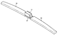
- FIG. 1 illustrates an example of the above described kind of conventional flat wiper blade assembly.
- the illustrated conventional flat wiper blade assembly generally comprises: a flexible wiper blade 14 to come into elastic contact with the glass surface of an automobile windshield; a rail spring 15 to maintain the shape of the wiper blade 14 ; an elastic member 12 to transfer the load of a wiper arm (not shown) to both the wiper blade 14 and the rail spring 15 ; yoke clips 13 to couple the elastic member 12 to the rail spring 15 and the wiper blade 14 ; and a wiper connector 11 to connect the wiper blade assembly to the wiper arm (not shown).
- the conventional flat wiper blade assembly further comprises caps 16 to prevent separation of the rail spring 15 .
- the conventional wiper blade assembly further comprises a spoiler.
- the conventional wiper blade assembly has a significantly complicated configuration and suffers from the enormous number of constituent elements. For this reason, there are some problems in that a variety of constituent elements should be made in the course of fabricating the wiper blade assembly and the resulting wiper blade assembly has a need for a troublesome assembling operation of the constituent elements.
- the present invention has been made in view of the above problems of the conventional wiper blade assembly, and it is an object of the present invention to provide a wiper blade assembly of a simplified configuration consisting of a wiper blade, elastic member, and spoiler without requiring a rail spring, yoke clips, and caps, thereby achieving a reduction in the number of constituent elements and consequently, the easy assembling operation of the constituent elements.
- a wiper blade assembly to be connected to an automobile wiper arm by means of a connector while coming into contact with the glass surface of an automobile windshield
- the wiper blade assembly comprising: a flexible blade including a blade edge, a receiving groove formed in a side surface thereof to extend along a longitudinal direction of the blade, and separation-preventing stepped portions formed at both longitudinal ends of the receiving groove; an elastic member originally having a predetermined curvature and configured to extend the longitudinal direction of the blade, the elastic member including a coupling portion to be received into the receiving groove of the flexible blade and a surplus portion not to be received in the receiving groove, the surplus portion having spoiler fitting holes; and a spoiler including protrusions to be fitted into the fitting holes of the elastic member, and a guiding/receiving structure to guide the insertion of the elastic member so as to receive the surplus portion of the elastic member.
- a wiper blade assembly comprising: a flexible blade including a blade edge formed at a lower surface thereof, two receiving grooves formed in opposite side surfaces thereof to extend along a longitudinal direction of the blade, and separation-preventing stepped portions formed at both longitudinal ends of each receiving groove; two elastic members originally having a predetermined curvature and configured to extend the longitudinal direction of the blade, each elastic member including a coupling portion to be received into the associated receiving groove of the flexible blade and a surplus portion not to be received in the receiving groove, the surplus portion having spoiler fitting holes; and a spoiler including protrusions to be fitted into the fitting holes of the elastic member, and two guiding/receiving structures to guide the insertion of the two elastic members so as to receive the surplus portions of the elastic members, respectively.
- FIG. 1 is a side view of a conventional wiper blade assembly
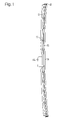
- FIG. 2 is an exploded perspective view of a wiper blade assembly according to the present invention
- FIG. 3 is a perspective view of the completed wiper blade assembly according to the present invention.
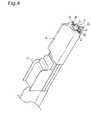
- FIG. 4 is a perspective view illustrating the cross section of the wiper blade assembly of FIG. 3 ;
- FIG. 5 is a side sectional view of the completed wiper blade assembly of FIG. 3 ;
- FIG. 6 is a rear view of the completed wiper blade assembly of FIG. 3 .
- FIG. 2 is an exploded perspective view illustrating the coupling relationship of a flexible wiper blade and elastic members included in a wiper blade assembly according to an embodiment of the present invention.
- the flexible wiper blade 21 of the wiper blade assembly includes: a blade edge 23 ; at least one receiving groove 22 ; and separation-preventing stepped portions 26 .
- the blade 21 has a function of removing impurities on the glass surface of an automobile windshield while coming into close contact with the glass surface.
- the blade 21 has a flexibility sufficient to easily come into close contact with the glass surface.
- the flexible blade 21 is made of rubber.
- the blade edge 23 is mounted to a lower surface of the wiper blade 21 and has an end to come into close contact with the glass surface. Accordingly, the blade edge 23 is actually used to remove impurities on the glass surface.
- the receiving groove 22 is formed in a side surface of the blade 21 along a longitudinal direction of the blade 21 .
- the size of the receiving groove 22 is determined such that it receives the elastic member 24 therein.
- a pair of receiving grooves 22 are formed in left and right side surfaces of the blade 21 , respectively, such that a pair of elastic members can support the blade 21 at left and right sides of the blade 21 .
- the receiving groove 22 of the blade 21 has a width slightly smaller than a thickness of the elastic member 24 .
- the blade 21 which is made of rubber, has elasticity. Therefore, even if the elastic member 24 has a thickness larger than the width of the receiving groove 22 , the elastic member 24 can be sufficiently received in the receiving groove 22 of the blade 21 , and has no risk of being unintentionally separated from the receiving groove 22 .
- the separation-preventing stepped portions 26 are illustrated in the partially enlarged parts of FIG. 2 .
- the separation-preventing stepped portions 26 are formed at both longitudinal ends of the blade 21 and have a function of preventing the elastic member 24 from being separated from the receiving groove 22 .
- the elastic member 24 may be separated in a longitudinal direction of the blade 21 when being unintentionally slipped in the receiving groove 22 . Accordingly, the separation-preventing stepped portions 26 serve to stably secure the elastic member 24 in the blade 21 .
- the present embodiment has the effect of more surely preventing the separation of the elastic member 24 without wiper caps that have been essentially used in a conventional wiper blade assembly.
- the elastic member 24 has a function of maintaining the shape of the blade 21 in consideration of the fact that the blade is made of a flexible material such as rubber and thus, has a difficulty to maintain its original shape. Another function of the elastic member 24 is to transfer the load of a wiper arm to the blade 21 .
- the elastic member 24 includes: fitting holes 25 ; a coupling portion 27 ; and a surplus portion 28 .
- the elastic member 24 is generally made of an elastic metal.
- each fitting hole 25 is perforated in a side surface of the elastic member 24 and used to securely fix the elastic member 24 to the spoiler 30 .
- the fitting hole 25 may be formed by simply cutting a part of the elastic member 24 .
- the fitting hole 25 is perforated in the surplus portion 28 of the elastic member 24 at a position suitable for the fitting of the spoiler 30 .
- the coupling portion 27 is a part of the elastic member 24 to be received into the receiving groove 22 .
- the surplus portion 28 is the remaining part of the elastic member 24 not to be received in the receiving groove 22 .
- the coupling portion 27 and the surplus portion 28 are integrally formed with each other, and for the sake of simplicity, are considered as one part to be received into the receiving groove 22 and the other part not to be received in the receiving groove 22 .
- the elastic member 24 has a length longer than the inner longitudinal length of a receiving space that is defined by the receiving groove 22 and the separation-preventing stepped portions 26 . That is to say, the length of the coupling portion 27 of the elastic member 24 , to be received into the receiving groove 22 , is longer than a distance between the separation-preventing stepped portions 26 formed at both the longitudinal ends of the receiving groove 22 .
- the flexible blade 21 is further extendible on the nature of flexibility thereof so as to enclose the elastic member 24 .
- the elastic member 24 can be strongly coupled to the blade 21 .
- the spoiler 30 as shown in FIGS. 4 and 5 , has an inclined upper surface, and has a function of preventing lifting of the wiper blade assembly during automobile traveling.
- the spoiler 30 includes protrusions 31 , and at least one guiding/receiving structure 32 .
- the protrusions 31 are formed at either inner side surface of the spoiler 30 , and configured to have a female-male coupling with the fitting holes 25 perforated in the surplus portion 28 of the elastic member 24 . Thereby, the protrusions 31 serve to prevent relative movements between the spoiler 30 and the elastic member 24 .
- the guiding/receiving structure 32 takes the form of a rail formed at either inner side surfaces of the spoiler 30 .
- the guiding/receiving structure 32 is capable of guiding and receiving the surplus portions 28 of the elastic member 24 .
- the reason why the structure 32 is called “guiding/receiving structure” is that the elastic member 24 can be inserted into the spoiler 30 along the rail-shaped guiding/receiving structure 32 .
- the guiding/receiving structure 32 is configured to receive the surplus portion 28 so as to enclose the elastic member 24 as shown in FIGS. 4 and 5 .
- the elastic member 24 can be coupled to the spoiler 30 and consequently, the blade 21 , which was previously coupled to the elastic member 24 , can be coupled to the spoiler 30 .
- the spoiler 30 may have an integral configuration or a dividable configuration as occasion demands.
- the spoiler 30 has an integral configuration, the spoiler 30 is perforated with a through-hole at the center of a longitudinal direction thereof such that the wiper connector 11 is coupled to the elastic member 24 by penetrating through the spoiler 30 .
- the spoiler 30 has a dividable configuration, the spoiler 30 is divided into two left and right parts on the basis of the coupling location of the wiper connector 11 .
- the elastic member 24 is inserted into the receiving groove 22 of the blade 21 .
- the insertion of the elastic member 24 is performed by stretching the blade 21 in a longitudinal direction thereof so as to elastically increase the length of the receiving groove 22 by a length sufficient for the insertion of the elastic member 24 . Then, if a stretching force of the blade 21 is removed, the elastic member 24 can be elastically caught by the separation-preventing stepped portions 26 and securely received in the receiving groove 22 .
- the elastic member 24 and the spoiler 30 are stably coupled to each other without the risk of relative movements. Consequently, the blade 21 , which was previously coupled to the elastic member 24 , is stably coupled to the spoiler 30 .
- the resulting wiper blade assembly will be coupled to a wiper arm (not shown) by use of the wiper connector 11 such that the load of the wiper arm is transferred to the elastic member 24 through the wiper connector 11 . Accordingly, the elastic member 24 acts to push the blade 21 upon receiving the load of the wiper arm, thereby allowing the blade 21 to come into close contact with the glass surface of an automobile windshield.
- the present invention provides a wiper blade assembly having a simplified configuration requiring no rail spring, yoke clips, wiper caps, etc. which have been essentially used in a conventional wiper blade assembly.
- a pair of elastic members are coupled to the blade such that a part of each elastic member protrudes out of the blade, and a spoiler is coupled to the elastic members.
- the wiper blade assembly of the present invention can achieve a reduction in the number of overall constituent elements and guarantee the easy fabrication and assembling operation of the elements.
Landscapes
- Engineering & Computer Science (AREA)
- Mechanical Engineering (AREA)
- Fittings On The Vehicle Exterior For Carrying Loads, And Devices For Holding Or Mounting Articles (AREA)
- Cleaning In General (AREA)
- Body Structure For Vehicles (AREA)
- Rotary Pumps (AREA)
- Structures Of Non-Positive Displacement Pumps (AREA)
- Braking Arrangements (AREA)
- Rear-View Mirror Devices That Are Mounted On The Exterior Of The Vehicle (AREA)
Abstract
Description
- 1. Field of the Invention
- The present invention relates to a wiper blade assembly which is connected to an automobile wiper arm via a connector and configured to come into close contact with the glass surface of an automobile windshield, and, more particularly, to a wiper blade assembly which has a simplified configuration capable of reducing the number of constituent elements and enabling the easy assembling operation of the constituent elements.
- 2. Description of the Related Art
- A wiper has a function of removing impurities on the glass surface of an automobile windshield while coming into close contact with the curved glass surface. To guarantee the close contact between the wiper and the curved glass surface, there are employed several methods, for example, a method for uniformly distributing a press pressure force applied by a wiper arm to a wiper blade, and a method for providing a wiper blade assembly originally having a curvature.
- A wiper, using the latter method for imparting the wiper blade assembly with a curvature suitable to come into contact with the glass surface, is called a flat wiper. The present invention deals with a flat wiper blade assembly. As will be expected, the wiper blade assembly, originally having the curvature, also has elasticity. Therefore, the flexible and elastic wiper blade assembly has no problem of coming into close contact with the glass surface even if there is no separate structure for distributing the load of the wiper arm and consequently, has an advantage of achieving a simplified configuration.
-
FIG. 1 illustrates an example of the above described kind of conventional flat wiper blade assembly. The illustrated conventional flat wiper blade assembly generally comprises: aflexible wiper blade 14 to come into elastic contact with the glass surface of an automobile windshield; arail spring 15 to maintain the shape of thewiper blade 14; anelastic member 12 to transfer the load of a wiper arm (not shown) to both thewiper blade 14 and therail spring 15;yoke clips 13 to couple theelastic member 12 to therail spring 15 and thewiper blade 14; and awiper connector 11 to connect the wiper blade assembly to the wiper arm (not shown). The conventional flat wiper blade assembly further comprisescaps 16 to prevent separation of therail spring 15. - Although not shown, to increase the contact efficiency of the wiper blade assembly, the conventional wiper blade assembly further comprises a spoiler. In conclusion, the conventional wiper blade assembly has a significantly complicated configuration and suffers from the enormous number of constituent elements. For this reason, there are some problems in that a variety of constituent elements should be made in the course of fabricating the wiper blade assembly and the resulting wiper blade assembly has a need for a troublesome assembling operation of the constituent elements.
- Therefore, the present invention has been made in view of the above problems of the conventional wiper blade assembly, and it is an object of the present invention to provide a wiper blade assembly of a simplified configuration consisting of a wiper blade, elastic member, and spoiler without requiring a rail spring, yoke clips, and caps, thereby achieving a reduction in the number of constituent elements and consequently, the easy assembling operation of the constituent elements.
- In accordance with one aspect of the present invention, the above and other objects can be accomplished by the provision of a wiper blade assembly to be connected to an automobile wiper arm by means of a connector while coming into contact with the glass surface of an automobile windshield, the wiper blade assembly comprising: a flexible blade including a blade edge, a receiving groove formed in a side surface thereof to extend along a longitudinal direction of the blade, and separation-preventing stepped portions formed at both longitudinal ends of the receiving groove; an elastic member originally having a predetermined curvature and configured to extend the longitudinal direction of the blade, the elastic member including a coupling portion to be received into the receiving groove of the flexible blade and a surplus portion not to be received in the receiving groove, the surplus portion having spoiler fitting holes; and a spoiler including protrusions to be fitted into the fitting holes of the elastic member, and a guiding/receiving structure to guide the insertion of the elastic member so as to receive the surplus portion of the elastic member.
- In accordance with another aspect of the present invention, the above and other objects can be accomplished by the provision of a wiper blade assembly comprising: a flexible blade including a blade edge formed at a lower surface thereof, two receiving grooves formed in opposite side surfaces thereof to extend along a longitudinal direction of the blade, and separation-preventing stepped portions formed at both longitudinal ends of each receiving groove; two elastic members originally having a predetermined curvature and configured to extend the longitudinal direction of the blade, each elastic member including a coupling portion to be received into the associated receiving groove of the flexible blade and a surplus portion not to be received in the receiving groove, the surplus portion having spoiler fitting holes; and a spoiler including protrusions to be fitted into the fitting holes of the elastic member, and two guiding/receiving structures to guide the insertion of the two elastic members so as to receive the surplus portions of the elastic members, respectively.
- The above and other objects, features and other advantages of the present invention will be more clearly understood from the following detailed description taken in conjunction with the accompanying drawings, in which:
-
FIG. 1 is a side view of a conventional wiper blade assembly; -
FIG. 2 is an exploded perspective view of a wiper blade assembly according to the present invention; -
FIG. 3 is a perspective view of the completed wiper blade assembly according to the present invention; -
FIG. 4 is a perspective view illustrating the cross section of the wiper blade assembly ofFIG. 3 ; -
FIG. 5 is a side sectional view of the completed wiper blade assembly ofFIG. 3 ; and -
FIG. 6 is a rear view of the completed wiper blade assembly ofFIG. 3 . - Now, preferred embodiments of the present invention will be described with reference to the accompanying drawings.
-
FIG. 2 is an exploded perspective view illustrating the coupling relationship of a flexible wiper blade and elastic members included in a wiper blade assembly according to an embodiment of the present invention. - As shown in
FIG. 2 , theflexible wiper blade 21 of the wiper blade assembly includes: ablade edge 23; at least one receivinggroove 22; and separation-preventingstepped portions 26. Theblade 21 has a function of removing impurities on the glass surface of an automobile windshield while coming into close contact with the glass surface. Theblade 21 has a flexibility sufficient to easily come into close contact with the glass surface. Generally, theflexible blade 21 is made of rubber. - The
blade edge 23 is mounted to a lower surface of thewiper blade 21 and has an end to come into close contact with the glass surface. Accordingly, theblade edge 23 is actually used to remove impurities on the glass surface. - The
receiving groove 22 is formed in a side surface of theblade 21 along a longitudinal direction of theblade 21. The size of the receivinggroove 22 is determined such that it receives theelastic member 24 therein. In a preferred embodiment, a pair of receivinggrooves 22 are formed in left and right side surfaces of theblade 21, respectively, such that a pair of elastic members can support theblade 21 at left and right sides of theblade 21. - Preferably, the
receiving groove 22 of theblade 21 has a width slightly smaller than a thickness of theelastic member 24. Theblade 21, which is made of rubber, has elasticity. Therefore, even if theelastic member 24 has a thickness larger than the width of the receivinggroove 22, theelastic member 24 can be sufficiently received in the receivinggroove 22 of theblade 21, and has no risk of being unintentionally separated from thereceiving groove 22. - The separation-preventing
stepped portions 26 are illustrated in the partially enlarged parts ofFIG. 2 . The separation-preventingstepped portions 26 are formed at both longitudinal ends of theblade 21 and have a function of preventing theelastic member 24 from being separated from thereceiving groove 22. - If there is no separation-preventing
stepped portions 26, theelastic member 24 may be separated in a longitudinal direction of theblade 21 when being unintentionally slipped in thereceiving groove 22. Accordingly, the separation-preventingstepped portions 26 serve to stably secure theelastic member 24 in theblade 21. - With the provision of the separation-preventing
stepped portions 26, the present embodiment has the effect of more surely preventing the separation of theelastic member 24 without wiper caps that have been essentially used in a conventional wiper blade assembly. - The
elastic member 24 has a function of maintaining the shape of theblade 21 in consideration of the fact that the blade is made of a flexible material such as rubber and thus, has a difficulty to maintain its original shape. Another function of theelastic member 24 is to transfer the load of a wiper arm to theblade 21. Theelastic member 24 includes: fittingholes 25; acoupling portion 27; and asurplus portion 28. Theelastic member 24 is generally made of an elastic metal. - As shown in
FIG. 6 , eachfitting hole 25 is perforated in a side surface of theelastic member 24 and used to securely fix theelastic member 24 to thespoiler 30. Thefitting hole 25 may be formed by simply cutting a part of theelastic member 24. Preferably, thefitting hole 25 is perforated in thesurplus portion 28 of theelastic member 24 at a position suitable for the fitting of thespoiler 30. - As shown in
FIGS. 4 , 5, and 6, thecoupling portion 27 is a part of theelastic member 24 to be received into the receivinggroove 22. Thesurplus portion 28 is the remaining part of theelastic member 24 not to be received in the receivinggroove 22. In the present embodiment, thecoupling portion 27 and thesurplus portion 28 are integrally formed with each other, and for the sake of simplicity, are considered as one part to be received into the receivinggroove 22 and the other part not to be received in the receivinggroove 22. - Preferably, the
elastic member 24 has a length longer than the inner longitudinal length of a receiving space that is defined by thereceiving groove 22 and the separation-preventingstepped portions 26. That is to say, the length of thecoupling portion 27 of theelastic member 24, to be received into thereceiving groove 22, is longer than a distance between the separation-preventingstepped portions 26 formed at both the longitudinal ends of thereceiving groove 22. - With the above described configuration, when the
elastic member 24 is fitted into thereceiving groove 22 of theblade 21, theflexible blade 21 is further extendible on the nature of flexibility thereof so as to enclose theelastic member 24. As a result, theelastic member 24 can be strongly coupled to theblade 21. - The
spoiler 30, as shown inFIGS. 4 and 5 , has an inclined upper surface, and has a function of preventing lifting of the wiper blade assembly during automobile traveling. Thespoiler 30 includesprotrusions 31, and at least one guiding/receivingstructure 32. - The
protrusions 31, as shown inFIG. 6 , are formed at either inner side surface of thespoiler 30, and configured to have a female-male coupling with the fitting holes 25 perforated in thesurplus portion 28 of theelastic member 24. Thereby, theprotrusions 31 serve to prevent relative movements between thespoiler 30 and theelastic member 24. - The guiding/receiving
structure 32, as shown inFIGS. 4 and 5 , takes the form of a rail formed at either inner side surfaces of thespoiler 30. The guiding/receivingstructure 32 is capable of guiding and receiving thesurplus portions 28 of theelastic member 24. Here, the reason why thestructure 32 is called “guiding/receiving structure” is that theelastic member 24 can be inserted into thespoiler 30 along the rail-shaped guiding/receivingstructure 32. - The guiding/receiving
structure 32 is configured to receive thesurplus portion 28 so as to enclose theelastic member 24 as shown inFIGS. 4 and 5 . In this way, theelastic member 24 can be coupled to thespoiler 30 and consequently, theblade 21, which was previously coupled to theelastic member 24, can be coupled to thespoiler 30. - In consideration of the fact that the
wiper connector 11 has to be coupled to theelastic member 24, thespoiler 30 may have an integral configuration or a dividable configuration as occasion demands. When thespoiler 30 has an integral configuration, thespoiler 30 is perforated with a through-hole at the center of a longitudinal direction thereof such that thewiper connector 11 is coupled to theelastic member 24 by penetrating through thespoiler 30. On the other hand, when thespoiler 30 has a dividable configuration, thespoiler 30 is divided into two left and right parts on the basis of the coupling location of thewiper connector 11. - Now, the coupling relationship and operation of the present embodiment will be described with reference to the accompanying drawings.
- To couple the
elastic member 24 to theflexible blade 21 as shown inFIG. 2 , theelastic member 24 is inserted into the receivinggroove 22 of theblade 21. In this case, since the longitudinal length of the receivinggroove 22 between the separation-preventing steppedportions 26 is shorter than the length of theelastic member 24, the insertion of theelastic member 24 is performed by stretching theblade 21 in a longitudinal direction thereof so as to elastically increase the length of the receivinggroove 22 by a length sufficient for the insertion of theelastic member 24. Then, if a stretching force of theblade 21 is removed, theelastic member 24 can be elastically caught by the separation-preventing steppedportions 26 and securely received in the receivinggroove 22. - After completion of the above described coupling operation, only the
coupling portion 27 of theelastic member 24 is received into the receivinggroove 22 and thesurplus portion 28 of theelastic member 24 is protruded out of theblade 21. Thesurplus portion 28, protruded out of theblade 21, is then inserted into and guided along the guiding/receivingstructure 32 of thespoiler 30 such that thesurplus portion 28 can be seated and received in the inner side surface of thespoiler 30 as shown inFIG. 6 . - If the fitting holes 25 included in the
surplus portion 28 have a female-male coupling with theprotrusions 31 of thespoiler 30, as shown inFIG. 3 , theelastic member 24 and thespoiler 30 are stably coupled to each other without the risk of relative movements. Consequently, theblade 21, which was previously coupled to theelastic member 24, is stably coupled to thespoiler 30. - The resulting wiper blade assembly will be coupled to a wiper arm (not shown) by use of the
wiper connector 11 such that the load of the wiper arm is transferred to theelastic member 24 through thewiper connector 11. Accordingly, theelastic member 24 acts to push theblade 21 upon receiving the load of the wiper arm, thereby allowing theblade 21 to come into close contact with the glass surface of an automobile windshield. - As apparent from the above description, the present invention provides a wiper blade assembly having a simplified configuration requiring no rail spring, yoke clips, wiper caps, etc. which have been essentially used in a conventional wiper blade assembly. Instead of using the above mentioned elements, in the wiper blade assembly of the present invention, a pair of elastic members are coupled to the blade such that a part of each elastic member protrudes out of the blade, and a spoiler is coupled to the elastic members.
- With the above described simplified configuration, the wiper blade assembly of the present invention can achieve a reduction in the number of overall constituent elements and guarantee the easy fabrication and assembling operation of the elements.
- Although the preferred embodiments of the present invention have been disclosed for illustrative purposes, those skilled in the art will appreciate that various modifications, additions and substitutions are possible, without departing from the scope and spirit of the invention as disclosed in the accompanying claims.
Claims (6)
Applications Claiming Priority (2)
| Application Number | Priority Date | Filing Date | Title |
|---|---|---|---|
| KR10-2006-0103802 | 2006-10-25 | ||
| KR1020060103802A KR100696609B1 (en) | 2006-10-25 | 2006-10-25 | Wiper blade assembly |
Publications (1)
| Publication Number | Publication Date |
|---|---|
| US20080098554A1 true US20080098554A1 (en) | 2008-05-01 |
Family
ID=39265056
Family Applications (1)
| Application Number | Title | Priority Date | Filing Date |
|---|---|---|---|
| US11/760,357 Abandoned US20080098554A1 (en) | 2006-10-25 | 2007-06-08 | Wiper blade assembly |
Country Status (8)
| Country | Link |
|---|---|
| US (1) | US20080098554A1 (en) |
| JP (1) | JP2008105660A (en) |
| KR (1) | KR100696609B1 (en) |
| CN (1) | CN101168362A (en) |
| DE (1) | DE102007028150A1 (en) |
| FR (1) | FR2907737A1 (en) |
| IT (1) | ITUD20070111A1 (en) |
| RU (1) | RU2346834C1 (en) |
Cited By (27)
| Publication number | Priority date | Publication date | Assignee | Title |
|---|---|---|---|---|
| USD647451S1 (en) * | 2011-01-30 | 2011-10-25 | Chin-Lien Lin | Windshield wiper |
| US20120266405A1 (en) * | 2011-04-21 | 2012-10-25 | Pylon Manufacturing Corp. | Vortex damping wiper blade |
| KR101318353B1 (en) * | 2011-09-21 | 2013-10-18 | (주) 에이피아이코리아 | Windshield wiper assembly |
| US20130333147A1 (en) * | 2010-12-13 | 2013-12-19 | Robert Bosch Gmbh | Wiper blade device |
| KR101387135B1 (en) | 2011-09-21 | 2014-04-22 | (주) 에이피아이코리아 | Windshield wiper assembly |
| US20140373298A1 (en) * | 2013-06-25 | 2014-12-25 | Trico Products Corporation | Airfoil for hybrid wiper assembly |
| KR101490990B1 (en) | 2010-12-13 | 2015-02-06 | 로베르트 보쉬 게엠베하 | Wiper blade device |
| US20150151715A1 (en) * | 2013-12-02 | 2015-06-04 | Trico Products Corporation | Coupler assembly for wiper assembly |
| US20150175132A1 (en) * | 2013-12-25 | 2015-06-25 | Unipoint Electric Mfg. Co. Ltd. | Wiper flow guider and wiper assembly |
| US9108595B2 (en) | 2011-07-29 | 2015-08-18 | Pylon Manufacturing Corporation | Windshield wiper connector |
| US9174609B2 (en) | 2011-04-21 | 2015-11-03 | Pylon Manufacturing Corp. | Wiper blade with cover |
| US9174611B2 (en) | 2011-07-28 | 2015-11-03 | Pylon Manufacturing Corp. | Windshield wiper adapter, connector and assembly |
| US9505380B2 (en) | 2014-03-07 | 2016-11-29 | Pylon Manufacturing Corp. | Windshield wiper connector and assembly |
| USD777079S1 (en) | 2014-10-03 | 2017-01-24 | Pylon Manufacturing Corp. | Wiper blade frame |
| USD787308S1 (en) | 2014-10-03 | 2017-05-23 | Pylon Manufacturing Corp. | Wiper blade package |
| US9669803B2 (en) | 2013-12-31 | 2017-06-06 | The Korea Development Bank | Wiper blade |
| US10077026B2 (en) | 2012-02-24 | 2018-09-18 | Pylon Manufacturing Corp. | Wiper blade |
| US10166951B2 (en) | 2013-03-15 | 2019-01-01 | Pylon Manufacturing Corp. | Windshield wiper connector |
| US10189445B2 (en) | 2012-02-24 | 2019-01-29 | Pylon Manufacturing Corp. | Wiper blade |
| US10363905B2 (en) | 2015-10-26 | 2019-07-30 | Pylon Manufacturing Corp. | Wiper blade |
| US10513246B2 (en) | 2016-05-19 | 2019-12-24 | Pylon Manufacturing Corp. | Windshield wiper connector |
| US10661759B2 (en) | 2016-05-19 | 2020-05-26 | Pylon Manufacturing Corporation | Windshield wiper connector |
| US10717414B2 (en) | 2016-05-19 | 2020-07-21 | Pylon Manufacturing Corporation | Windshield wiper blade |
| US10723322B2 (en) | 2012-02-24 | 2020-07-28 | Pylon Manufacturing Corp. | Wiper blade with cover |
| US10766462B2 (en) | 2016-05-19 | 2020-09-08 | Pylon Manufacturing Corporation | Windshield wiper connector |
| US10829092B2 (en) | 2012-09-24 | 2020-11-10 | Pylon Manufacturing Corp. | Wiper blade with modular mounting base |
| US11040705B2 (en) | 2016-05-19 | 2021-06-22 | Pylon Manufacturing Corp. | Windshield wiper connector |
Families Citing this family (6)
| Publication number | Priority date | Publication date | Assignee | Title |
|---|---|---|---|---|
| KR100846637B1 (en) | 2007-04-16 | 2008-07-16 | 케이씨더블류 주식회사 | Wiper blade assembly |
| US8413291B2 (en) * | 2009-09-10 | 2013-04-09 | Xiamen Meto Auto Parts Co., Ltd. | Boneless wiper blade |
| US8806700B2 (en) | 2011-07-29 | 2014-08-19 | Pylon Manufacturing Corporation | Wiper blade connector |
| KR101608257B1 (en) * | 2013-12-05 | 2016-04-11 | 케이씨더블류 주식회사 | Flat wiper blade and combination method |
| RU170916U1 (en) * | 2016-09-14 | 2017-05-15 | Александр Дмитриевич Кобельков | FRAMELESS WIPER BRUSH |
| WO2018052336A1 (en) | 2016-09-14 | 2018-03-22 | Александр Дмитриевич КОБЕЛЬКОВ | Frameless wiper blade |
Citations (5)
| Publication number | Priority date | Publication date | Assignee | Title |
|---|---|---|---|---|
| US3041654A (en) * | 1957-03-25 | 1962-07-03 | John W Anderson | Windshield wiper blade |
| US3902216A (en) * | 1973-02-01 | 1975-09-02 | Anderson Co | Anti-creep wiper blade element |
| US20050172443A1 (en) * | 2001-05-08 | 2005-08-11 | Sophie Genet | Windscreen wiper device |
| US6944905B2 (en) * | 2000-05-29 | 2005-09-20 | Robert Bosch Gmbh | Wiper blade for cleaning screens in particular on motor vehicles |
| US20070061993A1 (en) * | 2005-09-19 | 2007-03-22 | Alberee Products, Inc. | Windshield wiper assembly having a body made of spring steel |
Family Cites Families (14)
| Publication number | Priority date | Publication date | Assignee | Title |
|---|---|---|---|---|
| FR2613994B1 (en) * | 1987-04-17 | 1989-06-30 | Journee Paul Sa | AERODYNAMIC DEFLECTOR FOR WIPER BLADE AND WIPER BLADE PROVIDED WITH SUCH A DEFLECTOR |
| JPH02303958A (en) * | 1989-05-19 | 1990-12-17 | Ichikoh Ind Ltd | High speed wiper blade |
| JPH11165614A (en) * | 1997-12-01 | 1999-06-22 | Asmo Co Ltd | Wiper blade and rubber for wiper blade |
| DE19860644A1 (en) * | 1998-12-29 | 2000-07-06 | Bosch Gmbh Robert | Device for the articulated connection of a wiper blade for windows of motor vehicles with a wiper arm and method for producing this connection |
| DE10000398A1 (en) * | 2000-01-07 | 2001-07-12 | Volkswagen Ag | Method for determining injection parameters of a diesel internal combustion engine |
| DE10014803B4 (en) * | 2000-03-24 | 2017-02-09 | Valeo Auto-Electric Wischer Und Motoren Gmbh | wiper blade |
| DE10037338A1 (en) * | 2000-07-29 | 2002-02-21 | Valeo Auto Electric Gmbh | Windscreen wiper for vehicle; has spoiler-shaped extension along back of wiper rubber with bars and support blade to form under or over pressure in flow direction |
| JP2002370622A (en) * | 2001-06-15 | 2002-12-24 | Asmo Co Ltd | Wiper blade |
| US20040200026A1 (en) | 2003-04-12 | 2004-10-14 | Subramaniam Shanmugham | Retention member for a windshield wiper assembly |
| DE60310053T2 (en) * | 2003-06-26 | 2007-04-19 | Federal-Mogul S.A. | Windshield wiper device |
| JP2005349949A (en) * | 2004-06-10 | 2005-12-22 | Asmo Co Ltd | Blade rubber assembly and wiper blade |
| JP4254665B2 (en) * | 2004-09-03 | 2009-04-15 | 市光工業株式会社 | Wiper blade |
| DE202005020650U1 (en) * | 2005-02-03 | 2006-05-24 | Robert Bosch Gmbh | Wiper blade of a wind shield wiper with shield rail has wiper strip with at least plane beam-like supporting element and a spoiler and shield rail is supported at supporting element or spoiler |
| KR100629161B1 (en) * | 2005-06-20 | 2006-09-27 | 주식회사 캐프 | Car Wiper Blades |
-
2006
- 2006-10-25 KR KR1020060103802A patent/KR100696609B1/en not_active Expired - Fee Related
-
2007
- 2007-06-08 US US11/760,357 patent/US20080098554A1/en not_active Abandoned
- 2007-06-15 JP JP2007158834A patent/JP2008105660A/en active Pending
- 2007-06-18 CN CNA2007101114029A patent/CN101168362A/en active Pending
- 2007-06-18 IT IT000111A patent/ITUD20070111A1/en unknown
- 2007-06-19 DE DE102007028150A patent/DE102007028150A1/en not_active Withdrawn
- 2007-06-19 RU RU2007123034/11A patent/RU2346834C1/en not_active IP Right Cessation
- 2007-06-20 FR FR0755873A patent/FR2907737A1/en active Pending
Patent Citations (5)
| Publication number | Priority date | Publication date | Assignee | Title |
|---|---|---|---|---|
| US3041654A (en) * | 1957-03-25 | 1962-07-03 | John W Anderson | Windshield wiper blade |
| US3902216A (en) * | 1973-02-01 | 1975-09-02 | Anderson Co | Anti-creep wiper blade element |
| US6944905B2 (en) * | 2000-05-29 | 2005-09-20 | Robert Bosch Gmbh | Wiper blade for cleaning screens in particular on motor vehicles |
| US20050172443A1 (en) * | 2001-05-08 | 2005-08-11 | Sophie Genet | Windscreen wiper device |
| US20070061993A1 (en) * | 2005-09-19 | 2007-03-22 | Alberee Products, Inc. | Windshield wiper assembly having a body made of spring steel |
Cited By (42)
| Publication number | Priority date | Publication date | Assignee | Title |
|---|---|---|---|---|
| US10543813B2 (en) | 2010-02-10 | 2020-01-28 | Pylon Manufacturing Corp. | Wiper blade |
| KR101490990B1 (en) | 2010-12-13 | 2015-02-06 | 로베르트 보쉬 게엠베하 | Wiper blade device |
| US20130333147A1 (en) * | 2010-12-13 | 2013-12-19 | Robert Bosch Gmbh | Wiper blade device |
| US9387827B2 (en) * | 2010-12-13 | 2016-07-12 | Robert Bosch Gmbh | Wiper blade device |
| USD647451S1 (en) * | 2011-01-30 | 2011-10-25 | Chin-Lien Lin | Windshield wiper |
| US10005431B2 (en) | 2011-04-21 | 2018-06-26 | Pylon Manufacturing Corp. | Vortex damping wiper blade |
| US11124158B2 (en) | 2011-04-21 | 2021-09-21 | Pylon Manufacturing Corp. | Wiper blade with cover |
| US9174609B2 (en) | 2011-04-21 | 2015-11-03 | Pylon Manufacturing Corp. | Wiper blade with cover |
| US9457768B2 (en) * | 2011-04-21 | 2016-10-04 | Pylon Manufacturing Corp. | Vortex damping wiper blade |
| US20120266405A1 (en) * | 2011-04-21 | 2012-10-25 | Pylon Manufacturing Corp. | Vortex damping wiper blade |
| US10464533B2 (en) | 2011-04-21 | 2019-11-05 | Pylon Manufacturing Corp. | Wiper blade with cover |
| US9174611B2 (en) | 2011-07-28 | 2015-11-03 | Pylon Manufacturing Corp. | Windshield wiper adapter, connector and assembly |
| US10457252B2 (en) | 2011-07-28 | 2019-10-29 | Pylon Manufacturing Corp. | Windshield wiper adapter, connector and assembly |
| US10597004B2 (en) | 2011-07-29 | 2020-03-24 | Pylon Manufacturing Corporation | Windshield wiper connector |
| US9108595B2 (en) | 2011-07-29 | 2015-08-18 | Pylon Manufacturing Corporation | Windshield wiper connector |
| KR101318353B1 (en) * | 2011-09-21 | 2013-10-18 | (주) 에이피아이코리아 | Windshield wiper assembly |
| KR101387135B1 (en) | 2011-09-21 | 2014-04-22 | (주) 에이피아이코리아 | Windshield wiper assembly |
| US10723322B2 (en) | 2012-02-24 | 2020-07-28 | Pylon Manufacturing Corp. | Wiper blade with cover |
| US11180118B2 (en) | 2012-02-24 | 2021-11-23 | Pylon Manufacturing Corp. | Wiper blade |
| US11136002B2 (en) | 2012-02-24 | 2021-10-05 | Pylon Manufacturing Corp. | Wiper blade |
| US10077026B2 (en) | 2012-02-24 | 2018-09-18 | Pylon Manufacturing Corp. | Wiper blade |
| US10189445B2 (en) | 2012-02-24 | 2019-01-29 | Pylon Manufacturing Corp. | Wiper blade |
| US10829092B2 (en) | 2012-09-24 | 2020-11-10 | Pylon Manufacturing Corp. | Wiper blade with modular mounting base |
| US10166951B2 (en) | 2013-03-15 | 2019-01-01 | Pylon Manufacturing Corp. | Windshield wiper connector |
| US20140373298A1 (en) * | 2013-06-25 | 2014-12-25 | Trico Products Corporation | Airfoil for hybrid wiper assembly |
| US9493140B2 (en) * | 2013-12-02 | 2016-11-15 | Trico Products Corporation | Coupler assembly for wiper assembly |
| US20150151715A1 (en) * | 2013-12-02 | 2015-06-04 | Trico Products Corporation | Coupler assembly for wiper assembly |
| US20150175132A1 (en) * | 2013-12-25 | 2015-06-25 | Unipoint Electric Mfg. Co. Ltd. | Wiper flow guider and wiper assembly |
| US10065608B2 (en) * | 2013-12-25 | 2018-09-04 | Unipoint Electric Mfg. Co. Ltd. | Wiper flow guider and wiper assembly |
| US9669803B2 (en) | 2013-12-31 | 2017-06-06 | The Korea Development Bank | Wiper blade |
| US9505380B2 (en) | 2014-03-07 | 2016-11-29 | Pylon Manufacturing Corp. | Windshield wiper connector and assembly |
| US9889822B2 (en) | 2014-03-07 | 2018-02-13 | Pylon Manufacturing Corp. | Windshield wiper connector and assembly |
| USD777079S1 (en) | 2014-10-03 | 2017-01-24 | Pylon Manufacturing Corp. | Wiper blade frame |
| USD787308S1 (en) | 2014-10-03 | 2017-05-23 | Pylon Manufacturing Corp. | Wiper blade package |
| US11155241B2 (en) | 2015-10-26 | 2021-10-26 | Pylon Manufacturing Corp. | Windshield wiper blade |
| US10363905B2 (en) | 2015-10-26 | 2019-07-30 | Pylon Manufacturing Corp. | Wiper blade |
| US10661759B2 (en) | 2016-05-19 | 2020-05-26 | Pylon Manufacturing Corporation | Windshield wiper connector |
| US11040705B2 (en) | 2016-05-19 | 2021-06-22 | Pylon Manufacturing Corp. | Windshield wiper connector |
| US10766462B2 (en) | 2016-05-19 | 2020-09-08 | Pylon Manufacturing Corporation | Windshield wiper connector |
| US10717414B2 (en) | 2016-05-19 | 2020-07-21 | Pylon Manufacturing Corporation | Windshield wiper blade |
| US10513246B2 (en) | 2016-05-19 | 2019-12-24 | Pylon Manufacturing Corp. | Windshield wiper connector |
| US11554754B2 (en) | 2016-05-19 | 2023-01-17 | Pylon Manufacturing Corporation | Windshield wiper blade |
Also Published As
| Publication number | Publication date |
|---|---|
| KR100696609B1 (en) | 2007-03-19 |
| JP2008105660A (en) | 2008-05-08 |
| CN101168362A (en) | 2008-04-30 |
| ITUD20070111A1 (en) | 2008-04-26 |
| RU2346834C1 (en) | 2009-02-20 |
| FR2907737A1 (en) | 2008-05-02 |
| DE102007028150A1 (en) | 2008-05-08 |
Similar Documents
| Publication | Publication Date | Title |
|---|---|---|
| US20080098554A1 (en) | Wiper blade assembly | |
| US8261405B2 (en) | Wiper blade assembly having rotatable auxiliary beam | |
| JP3898186B2 (en) | Wiper blade assembly for vehicle | |
| US20090158547A1 (en) | Wiper blade assembly having multi-beam | |
| US8499408B2 (en) | Windshield wiper device | |
| US8671505B2 (en) | Windshield wiper blade assembly | |
| EP1800978B1 (en) | Wiper blade | |
| EP1681216B1 (en) | Windshield wiper device | |
| EP2889192B1 (en) | Wiper blade | |
| KR20070064286A (en) | Connector assembly | |
| KR20100002098A (en) | Windscreen wiper device comprising an elastic, elongated carrier element, as well as an elongated wiper blade of a flexible material, which can be placed in abutment with the windscreen to be wiped | |
| US9862356B2 (en) | Wiper blade | |
| US20100130075A1 (en) | Female Electrical Contact Comprising Spring Contact Plates | |
| KR100454874B1 (en) | Wiper Blade Assembly | |
| JP4436086B2 (en) | Wiper blade | |
| KR20240079406A (en) | Module clip for vehicles | |
| JP4544165B2 (en) | Wiper blade | |
| CN101528515A (en) | Wiper blade | |
| JP4100281B2 (en) | Mounting structure of wiper blade to wiper arm | |
| JP2019001438A (en) | Wiper blade | |
| KR100597339B1 (en) | Wiper blade assembly | |
| JP5410321B2 (en) | Composite terminal fitting | |
| EP2599673B1 (en) | Wiper blade | |
| KR20040073668A (en) | Wiper for Motor Vehicle | |
| CN2390305Y (en) | Holding device |
Legal Events
| Date | Code | Title | Description |
|---|---|---|---|
| AS | Assignment |
Owner name: KWC CORPORATION, KOREA, REPUBLIC OF Free format text: ASSIGNMENT OF ASSIGNORS INTEREST;ASSIGNOR:CHO, KYUNG-HEE;REEL/FRAME:019403/0214 Effective date: 20070424 |
|
| AS | Assignment |
Owner name: KCW CORPORATION, KOREA, REPUBLIC OF Free format text: CORRECTIVE ASSIGNMENT TO CORRECT THE ASSIGNEE'S NAME PREVIOUSLY RECORDED ON REEL 019403 FRAME 0214;ASSIGNOR:CHO, KYUNG-HEE;REEL/FRAME:019604/0843 Effective date: 20070424 |
|
| STCB | Information on status: application discontinuation |
Free format text: ABANDONED -- FAILURE TO RESPOND TO AN OFFICE ACTION |