US20080098511A1 - Resin infused acrylic shell - Google Patents
Resin infused acrylic shell Download PDFInfo
- Publication number
- US20080098511A1 US20080098511A1 US11/968,232 US96823208A US2008098511A1 US 20080098511 A1 US20080098511 A1 US 20080098511A1 US 96823208 A US96823208 A US 96823208A US 2008098511 A1 US2008098511 A1 US 2008098511A1
- Authority
- US
- United States
- Prior art keywords
- shell
- resin
- fiber mat
- infused
- bathtub
- Prior art date
- Legal status (The legal status is an assumption and is not a legal conclusion. Google has not performed a legal analysis and makes no representation as to the accuracy of the status listed.)
- Abandoned
Links
Images

Classifications
-
- B—PERFORMING OPERATIONS; TRANSPORTING
- B29—WORKING OF PLASTICS; WORKING OF SUBSTANCES IN A PLASTIC STATE IN GENERAL
- B29C—SHAPING OR JOINING OF PLASTICS; SHAPING OF MATERIAL IN A PLASTIC STATE, NOT OTHERWISE PROVIDED FOR; AFTER-TREATMENT OF THE SHAPED PRODUCTS, e.g. REPAIRING
- B29C70/00—Shaping composites, i.e. plastics material comprising reinforcements, fillers or preformed parts, e.g. inserts
- B29C70/04—Shaping composites, i.e. plastics material comprising reinforcements, fillers or preformed parts, e.g. inserts comprising reinforcements only, e.g. self-reinforcing plastics
- B29C70/06—Fibrous reinforcements only
- B29C70/08—Fibrous reinforcements only comprising combinations of different forms of fibrous reinforcements incorporated in matrix material, forming one or more layers, and with or without non-reinforced layers
- B29C70/086—Fibrous reinforcements only comprising combinations of different forms of fibrous reinforcements incorporated in matrix material, forming one or more layers, and with or without non-reinforced layers and with one or more layers of pure plastics material, e.g. foam layers
-
- A—HUMAN NECESSITIES
- A47—FURNITURE; DOMESTIC ARTICLES OR APPLIANCES; COFFEE MILLS; SPICE MILLS; SUCTION CLEANERS IN GENERAL
- A47K—SANITARY EQUIPMENT; ACCESSORIES THEREFOR, e.g. TOILET ACCESSORIES
- A47K3/00—Baths; Showers; Appurtenances therefor
- A47K3/02—Baths
-
- B—PERFORMING OPERATIONS; TRANSPORTING
- B29—WORKING OF PLASTICS; WORKING OF SUBSTANCES IN A PLASTIC STATE IN GENERAL
- B29C—SHAPING OR JOINING OF PLASTICS; SHAPING OF MATERIAL IN A PLASTIC STATE, NOT OTHERWISE PROVIDED FOR; AFTER-TREATMENT OF THE SHAPED PRODUCTS, e.g. REPAIRING
- B29C70/00—Shaping composites, i.e. plastics material comprising reinforcements, fillers or preformed parts, e.g. inserts
- B29C70/04—Shaping composites, i.e. plastics material comprising reinforcements, fillers or preformed parts, e.g. inserts comprising reinforcements only, e.g. self-reinforcing plastics
- B29C70/28—Shaping operations therefor
- B29C70/40—Shaping or impregnating by compression not applied
- B29C70/42—Shaping or impregnating by compression not applied for producing articles of definite length, i.e. discrete articles
- B29C70/44—Shaping or impregnating by compression not applied for producing articles of definite length, i.e. discrete articles using isostatic pressure, e.g. pressure difference-moulding, vacuum bag-moulding, autoclave-moulding or expanding rubber-moulding
- B29C70/443—Shaping or impregnating by compression not applied for producing articles of definite length, i.e. discrete articles using isostatic pressure, e.g. pressure difference-moulding, vacuum bag-moulding, autoclave-moulding or expanding rubber-moulding and impregnating by vacuum or injection
-
- B—PERFORMING OPERATIONS; TRANSPORTING
- B29—WORKING OF PLASTICS; WORKING OF SUBSTANCES IN A PLASTIC STATE IN GENERAL
- B29L—INDEXING SCHEME ASSOCIATED WITH SUBCLASS B29C, RELATING TO PARTICULAR ARTICLES
- B29L2031/00—Other particular articles
- B29L2031/769—Sanitary equipment
- B29L2031/7692—Baths
Definitions
- This invention relates to an improved method of forming a reinforced bathtub shell.
- tubs such as utilized in bathtubs, whirlpools, etc.
- the thin acrylic shell is typically reinforced.
- One standard method of reinforcing the shell is an open mold spray process, wherein reinforcing fibers are sprayed onto a rear face of the shell.
- This spray process requires extensive exhaust air control, including an enclosed space, air handling equipment, etc. Further, permits from government environmental agencies are required for the system.
- an acrylic shell is placed upon a support fixture having a fluidized bed for floating the shell.
- This fluidized bed will compensate for any irregularities in the formation of the individual shells.
- a vacuum is drawn to pull the shell against the support, floating on the fluidized bed.
- a fiber mat or reinforcement is then placed upon the rear of the acrylic shell, and an enclosure, in one embodiment a vacuum bag, is placed around the shell, enclosing the fiber mat. Resin is infused into a port in the vacuum bag, and the resin penetrates and infuses the fiber mat. As the resin cures, the fiber mat hardens against the shell, forming a final bathtub shell.
- the water that is utilized as the fluidized bed can be controlled to facilitate the curing process of the infused resin.
- hot water may be utilized.
- cool water may be utilized to facilitate the curing.
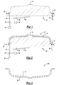
- FIG. 1 shows a fixture for forming a bathtub.
- FIG. 2 shows the fixture in a first step according to the present invention.
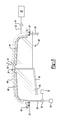
- FIG. 3 shows the fixture in a final step.
- FIG. 4 shows a rough schematic of a bathtub shell formed according to this invention.
- FIG. 1 shows a fixture 20 , having a gasket seal 22 at an outer periphery, and defining a vacuum chamber 24 between the two gasket seal portions.
- a source of vacuum 26 is connected to the vacuum chamber 24 .
- a water connection 28 extends to a valve 30 that can selectively deliver either a cool water from a cool water source 32 or a warmer water from a warm water source 34 to the connection 28 .
- a drain 36 is formed at an uppermost portion of the fixture 20 and drains water through a pipe 38 controlled by a valve 40 .
- FIG. 2 shows a first step in forming the inventive bathtub.
- a molded acrylic shell 42 is placed on the fixture 20 .
- a fluidized bed 44 is created between an inner surface of the shell 42 and an outer surface of the fixture 20 .
- Water is delivered through the pipe 28 , and into the small clearance between the shell and the fixture 20 . Excess water will flow through the drain 36 , and outwardly through pipe 38 .
- the fixture 20 is preferably formed such that there will be an intended small clearance relative to shell 42 on the order of, for example, 0.060 inch, to provide the fluidized bed.
- the fluidized bed ensures that the shell 42 will be firmly supported, regardless of any surface irregularities in the individual formation of the shell 42 .
- the vacuum is drawn on the vacuum chamber 24 and pulls the shell 42 downwardly against the fluidized bed 44 and fixture 20 .
- a fiber mat 46 is placed upon a rear surface of the shell 42 .
- the fluidized bed is still floating the shell 42 and the fiber mat 46 .
- a vacuum bag 49 with a seal 58 at an outer periphery is placed around and sealed to the shell 42 .
- the vacuum bag 49 could also be sealed to the fixture, or could be sealed to some other structure.
- the bag 49 has a connection 50 to a vacuum source.
- a resin infusion port 52 extends through a valve 54 to a source of resin 56 .
- a vacuum 50 is pulled within the vacuum bag 49 . Resin is injected through the port 52 and flows to infuse the fiber mat 46 . Once sufficient resin has been flowed into the vacuum bag 49 such that the fiber mat 46 is infused, the mat is allowed to cure.
- the fluidized bed 44 can be utilized to facilitate the curing, such as by utilizing hot water from hot water source 34 while the resin is flowing into the vacuum bag 49 , and then switching to cool water from the cool water source 32 to assist in curing.
- FIG. 4 shows the final bathtub 100 with shell 42 and having an underlying support surface from fiber mat 46 .
- the present invention thus provides a less cumbersome method of forming a fiber-reinforced acrylic shell for use as a bathtub.
- bath as utilized in this application extends beyond the traditional bathtub to cover whirlpools, or any other relatively large container for receiving water or other liquids.
Landscapes
- Health & Medical Sciences (AREA)
- Public Health (AREA)
- Chemical & Material Sciences (AREA)
- Engineering & Computer Science (AREA)
- Composite Materials (AREA)
- Mechanical Engineering (AREA)
- Epidemiology (AREA)
- General Health & Medical Sciences (AREA)
- Casting Or Compression Moulding Of Plastics Or The Like (AREA)
Abstract
An improved method of forming fiber-reinforced plastic shells for bathtubs utilizes a fiber mat placed on a rear surface of a plastic shell. The fiber mat is infused with a resin, and is then cured. The mat and resin are preferably received within a vacuum chamber as the resin is infused. Further, the plastic shell is preferably supported on a fluidized bed during this process. The present invention eliminates the need for detailed air handling as is now required to handle impurities in the industrial air around the process of forming the bathtub shell.
Description
- This application is a divisional of U.S. patent application Ser. No. 10/966,651, filed Oct. 15, 2004.
- This invention relates to an improved method of forming a reinforced bathtub shell.
- Currently, tubs such as utilized in bathtubs, whirlpools, etc., are often molded from acrylic. The thin acrylic shell is typically reinforced. One standard method of reinforcing the shell is an open mold spray process, wherein reinforcing fibers are sprayed onto a rear face of the shell.
- This spray process requires extensive exhaust air control, including an enclosed space, air handling equipment, etc. Further, permits from government environmental agencies are required for the system.
- In addition, the percentage content of resin is somewhat limited by the spray process.
- In a disclosed embodiment of this invention, an acrylic shell is placed upon a support fixture having a fluidized bed for floating the shell. This fluidized bed will compensate for any irregularities in the formation of the individual shells. A vacuum is drawn to pull the shell against the support, floating on the fluidized bed.
- A fiber mat or reinforcement is then placed upon the rear of the acrylic shell, and an enclosure, in one embodiment a vacuum bag, is placed around the shell, enclosing the fiber mat. Resin is infused into a port in the vacuum bag, and the resin penetrates and infuses the fiber mat. As the resin cures, the fiber mat hardens against the shell, forming a final bathtub shell.
- The water that is utilized as the fluidized bed can be controlled to facilitate the curing process of the infused resin. As an example, to assist in resin flow, while resin is being injected into the vacuum bag, hot water may be utilized. Once the fiber mat has been infused, cool water may be utilized to facilitate the curing.
- These and other features of the present invention can be best understood from the following specification and drawings, the following of which is a brief description.
-
FIG. 1 shows a fixture for forming a bathtub. -
FIG. 2 shows the fixture in a first step according to the present invention. -
FIG. 3 shows the fixture in a final step. -
FIG. 4 shows a rough schematic of a bathtub shell formed according to this invention. -
FIG. 1 shows afixture 20, having agasket seal 22 at an outer periphery, and defining avacuum chamber 24 between the two gasket seal portions. A source ofvacuum 26 is connected to thevacuum chamber 24. Further, awater connection 28 extends to avalve 30 that can selectively deliver either a cool water from acool water source 32 or a warmer water from awarm water source 34 to theconnection 28. - As shown, a
drain 36 is formed at an uppermost portion of thefixture 20 and drains water through apipe 38 controlled by avalve 40. -
FIG. 2 shows a first step in forming the inventive bathtub. A moldedacrylic shell 42 is placed on thefixture 20. As shown, a fluidizedbed 44 is created between an inner surface of theshell 42 and an outer surface of thefixture 20. Water is delivered through thepipe 28, and into the small clearance between the shell and thefixture 20. Excess water will flow through thedrain 36, and outwardly throughpipe 38. - The
fixture 20 is preferably formed such that there will be an intended small clearance relative toshell 42 on the order of, for example, 0.060 inch, to provide the fluidized bed. The fluidized bed ensures that theshell 42 will be firmly supported, regardless of any surface irregularities in the individual formation of theshell 42. The vacuum is drawn on thevacuum chamber 24 and pulls theshell 42 downwardly against the fluidizedbed 44 andfixture 20. - In the next step, as illustrated in
FIG. 3 , afiber mat 46 is placed upon a rear surface of theshell 42. The fluidized bed is still floating theshell 42 and thefiber mat 46. Avacuum bag 49 with aseal 58 at an outer periphery is placed around and sealed to theshell 42. Of course, thevacuum bag 49 could also be sealed to the fixture, or could be sealed to some other structure. Thebag 49 has aconnection 50 to a vacuum source. Aresin infusion port 52 extends through avalve 54 to a source ofresin 56. When forming the bathtub, avacuum 50 is pulled within thevacuum bag 49. Resin is injected through theport 52 and flows to infuse thefiber mat 46. Once sufficient resin has been flowed into thevacuum bag 49 such that thefiber mat 46 is infused, the mat is allowed to cure. - In one embodiment of this invention, the fluidized
bed 44 can be utilized to facilitate the curing, such as by utilizing hot water fromhot water source 34 while the resin is flowing into thevacuum bag 49, and then switching to cool water from thecool water source 32 to assist in curing. -
FIG. 4 shows thefinal bathtub 100 withshell 42 and having an underlying support surface fromfiber mat 46. - The present invention thus provides a less cumbersome method of forming a fiber-reinforced acrylic shell for use as a bathtub. Of course, the term “bathtub” as utilized in this application extends beyond the traditional bathtub to cover whirlpools, or any other relatively large container for receiving water or other liquids.
- Although a preferred embodiment of this invention has been disclosed, a worker of ordinary skill in this art would recognize that certain modifications would come within the scope of this invention. For that reason, the following claims should be studied to determine the true scope and content of this invention.
Claims (1)
1. A bathtub comprising:
an acrylic shell; and
an underlying fiber mat, said fiber mat being infused with a resin, such that said fiber mat is adhered to an under surface of said acrylic shell.
Priority Applications (1)
| Application Number | Priority Date | Filing Date | Title |
|---|---|---|---|
| US11/968,232 US20080098511A1 (en) | 2004-10-15 | 2008-01-02 | Resin infused acrylic shell |
Applications Claiming Priority (2)
| Application Number | Priority Date | Filing Date | Title |
|---|---|---|---|
| US10/966,651 US7338628B2 (en) | 2004-10-15 | 2004-10-15 | Resin infused acrylic shell |
| US11/968,232 US20080098511A1 (en) | 2004-10-15 | 2008-01-02 | Resin infused acrylic shell |
Related Parent Applications (1)
| Application Number | Title | Priority Date | Filing Date |
|---|---|---|---|
| US10/966,651 Division US7338628B2 (en) | 2004-10-15 | 2004-10-15 | Resin infused acrylic shell |
Publications (1)
| Publication Number | Publication Date |
|---|---|
| US20080098511A1 true US20080098511A1 (en) | 2008-05-01 |
Family
ID=36177438
Family Applications (3)
| Application Number | Title | Priority Date | Filing Date |
|---|---|---|---|
| US10/966,651 Expired - Fee Related US7338628B2 (en) | 2004-10-15 | 2004-10-15 | Resin infused acrylic shell |
| US11/968,229 Expired - Fee Related US7510385B2 (en) | 2004-10-15 | 2008-01-02 | Resin infused acrylic shell |
| US11/968,232 Abandoned US20080098511A1 (en) | 2004-10-15 | 2008-01-02 | Resin infused acrylic shell |
Family Applications Before (2)
| Application Number | Title | Priority Date | Filing Date |
|---|---|---|---|
| US10/966,651 Expired - Fee Related US7338628B2 (en) | 2004-10-15 | 2004-10-15 | Resin infused acrylic shell |
| US11/968,229 Expired - Fee Related US7510385B2 (en) | 2004-10-15 | 2008-01-02 | Resin infused acrylic shell |
Country Status (2)
| Country | Link |
|---|---|
| US (3) | US7338628B2 (en) |
| CA (1) | CA2516352A1 (en) |
Cited By (1)
| Publication number | Priority date | Publication date | Assignee | Title |
|---|---|---|---|---|
| US20250127342A1 (en) * | 2023-10-18 | 2025-04-24 | Maax Bath Inc. | Solid core bathroom fixtures and methods thereof |
Families Citing this family (9)
| Publication number | Priority date | Publication date | Assignee | Title |
|---|---|---|---|---|
| US6367406B1 (en) * | 1999-09-24 | 2002-04-09 | Larson/Glastron Boats, Inc. | Boat and method for manufacturing using resin transfer molding |
| US20080001396A1 (en) * | 2006-04-07 | 2008-01-03 | Nish Randy W | Pipe coupling and method |
| WO2008089334A2 (en) * | 2007-01-19 | 2008-07-24 | Vec Industries, L.L.C. | Method and apparatus for molding composite articles |
| WO2010048370A1 (en) * | 2008-10-22 | 2010-04-29 | Vec Industries, L.L.C. | Wind turbine blade and method for manufacturing thereof |
| US8105068B2 (en) * | 2008-11-05 | 2012-01-31 | Spirit Aerosystems, Inc. | Reusable infusion bag |
| ES2352771B1 (en) * | 2008-11-06 | 2012-02-10 | Alfonso Navarro Torres | BATH AND ITS MANUFACTURING METHOD. |
| US8298473B2 (en) | 2009-05-15 | 2012-10-30 | The Boeing Company | Method of making a cure tool with integrated edge breather |
| US8556618B2 (en) * | 2011-04-07 | 2013-10-15 | Spirit Aerosystems, Inc. | Method and bladder apparatus for forming composite parts |
| EP2781343B1 (en) * | 2013-03-22 | 2016-06-15 | Roca Sanitario, S. A. | Reinforcement system for acrylic sanitary products and acrylic sanitary product thus obtained |
Citations (4)
| Publication number | Priority date | Publication date | Assignee | Title |
|---|---|---|---|---|
| US2913036A (en) * | 1956-08-10 | 1959-11-17 | Anthony Bros Fibre Glass Pool | Process and apparatus for molding large plastic structures |
| US4943222A (en) * | 1989-04-17 | 1990-07-24 | Shell Oil Company | Apparatus for forming preformed material |
| US5580621A (en) * | 1990-04-30 | 1996-12-03 | American Standard Inc. | Polyester backed acrylic composite molded structure and method of manufacturing thereof |
| US6149844A (en) * | 1994-09-09 | 2000-11-21 | Decta Holdings Pty Ltd. | Method of manufacturing composites |
Family Cites Families (1)
| Publication number | Priority date | Publication date | Assignee | Title |
|---|---|---|---|---|
| US5074770A (en) * | 1989-08-30 | 1991-12-24 | Intellex Corporation | Integrated vacuum forming/reaction injection molding apparatus for manufacturing a shaped polymeric laminate article |
-
2004
- 2004-10-15 US US10/966,651 patent/US7338628B2/en not_active Expired - Fee Related
-
2005
- 2005-08-19 CA CA002516352A patent/CA2516352A1/en not_active Abandoned
-
2008
- 2008-01-02 US US11/968,229 patent/US7510385B2/en not_active Expired - Fee Related
- 2008-01-02 US US11/968,232 patent/US20080098511A1/en not_active Abandoned
Patent Citations (4)
| Publication number | Priority date | Publication date | Assignee | Title |
|---|---|---|---|---|
| US2913036A (en) * | 1956-08-10 | 1959-11-17 | Anthony Bros Fibre Glass Pool | Process and apparatus for molding large plastic structures |
| US4943222A (en) * | 1989-04-17 | 1990-07-24 | Shell Oil Company | Apparatus for forming preformed material |
| US5580621A (en) * | 1990-04-30 | 1996-12-03 | American Standard Inc. | Polyester backed acrylic composite molded structure and method of manufacturing thereof |
| US6149844A (en) * | 1994-09-09 | 2000-11-21 | Decta Holdings Pty Ltd. | Method of manufacturing composites |
Cited By (1)
| Publication number | Priority date | Publication date | Assignee | Title |
|---|---|---|---|---|
| US20250127342A1 (en) * | 2023-10-18 | 2025-04-24 | Maax Bath Inc. | Solid core bathroom fixtures and methods thereof |
Also Published As
| Publication number | Publication date |
|---|---|
| US7338628B2 (en) | 2008-03-04 |
| US7510385B2 (en) | 2009-03-31 |
| US20060080769A1 (en) | 2006-04-20 |
| US20080102154A1 (en) | 2008-05-01 |
| CA2516352A1 (en) | 2006-04-15 |
Similar Documents
| Publication | Publication Date | Title |
|---|---|---|
| US20080098511A1 (en) | Resin infused acrylic shell | |
| JP2725742B2 (en) | Manhole lining method | |
| JP2927407B2 (en) | Pipe lining method | |
| CN106564202B (en) | A kind of method that vacuum importing molding prepares the U-shaped part of hybrid composite | |
| TW319739B (en) | ||
| US20080185754A1 (en) | Method and apparatus for molding composite articles | |
| JP2000185351A (en) | Manhole lining material and manhole lining method | |
| US10052826B2 (en) | Bulk resin infusion | |
| CN110576625B (en) | One-way opening composite material box body forming method | |
| US5256366A (en) | Method of molding fiberglass | |
| US9211660B2 (en) | Adjustable support for preformed mold | |
| CA2525593A1 (en) | Method for the manufacture of a reinforced plastic product | |
| JP2003025347A (en) | Vacuum RTM molding method | |
| JP3472077B2 (en) | Manhole lining material and manhole lining method | |
| JP2006095727A (en) | RTM molding apparatus and method | |
| JPH09220764A (en) | Lining material for manhole and manhole lining method | |
| CN114454516B (en) | A simple method for preparing polyurethane composite fiberglass by vacuum infusion process | |
| JP2831899B2 (en) | Lining pump | |
| JPH0617072B2 (en) | Pipe line lining method | |
| CA2635292A1 (en) | Composite product | |
| US12043004B1 (en) | Fabrication apparatuses and methods | |
| JP2600060B2 (en) | Pipe forming method | |
| CN220749455U (en) | Repairing structure in glass fiber reinforced plastic pipeline | |
| WO2022125373A1 (en) | Method and apparatus for forming a composite object | |
| JPH07256767A (en) | Thermosetting resin molding die and molding method |
Legal Events
| Date | Code | Title | Description |
|---|---|---|---|
| STCB | Information on status: application discontinuation |
Free format text: ABANDONED -- FAILURE TO RESPOND TO AN OFFICE ACTION |