US20080098509A1 - Spa System - Google Patents
Spa System Download PDFInfo
- Publication number
- US20080098509A1 US20080098509A1 US11/930,803 US93080307A US2008098509A1 US 20080098509 A1 US20080098509 A1 US 20080098509A1 US 93080307 A US93080307 A US 93080307A US 2008098509 A1 US2008098509 A1 US 2008098509A1
- Authority
- US
- United States
- Prior art keywords
- upwardly
- cavity
- spa
- channel
- side wall
- Prior art date
- Legal status (The legal status is an assumption and is not a legal conclusion. Google has not performed a legal analysis and makes no representation as to the accuracy of the status listed.)
- Abandoned
Links
Images
Classifications
-
- A—HUMAN NECESSITIES
- A61—MEDICAL OR VETERINARY SCIENCE; HYGIENE
- A61H—PHYSICAL THERAPY APPARATUS, e.g. DEVICES FOR LOCATING OR STIMULATING REFLEX POINTS IN THE BODY; ARTIFICIAL RESPIRATION; MASSAGE; BATHING DEVICES FOR SPECIAL THERAPEUTIC OR HYGIENIC PURPOSES OR SPECIFIC PARTS OF THE BODY
- A61H33/00—Bathing devices for special therapeutic or hygienic purposes
- A61H33/0087—Therapeutic baths with agitated or circulated water
-
- A—HUMAN NECESSITIES
- A61—MEDICAL OR VETERINARY SCIENCE; HYGIENE
- A61H—PHYSICAL THERAPY APPARATUS, e.g. DEVICES FOR LOCATING OR STIMULATING REFLEX POINTS IN THE BODY; ARTIFICIAL RESPIRATION; MASSAGE; BATHING DEVICES FOR SPECIAL THERAPEUTIC OR HYGIENIC PURPOSES OR SPECIFIC PARTS OF THE BODY
- A61H33/00—Bathing devices for special therapeutic or hygienic purposes
- A61H33/60—Components specifically designed for the therapeutic baths of groups A61H33/00
- A61H33/6068—Outlet from the bath
-
- A—HUMAN NECESSITIES
- A61—MEDICAL OR VETERINARY SCIENCE; HYGIENE
- A61H—PHYSICAL THERAPY APPARATUS, e.g. DEVICES FOR LOCATING OR STIMULATING REFLEX POINTS IN THE BODY; ARTIFICIAL RESPIRATION; MASSAGE; BATHING DEVICES FOR SPECIAL THERAPEUTIC OR HYGIENIC PURPOSES OR SPECIFIC PARTS OF THE BODY
- A61H33/00—Bathing devices for special therapeutic or hygienic purposes
- A61H33/005—Electrical circuits therefor
- A61H2033/0083—Illumination
-
- A—HUMAN NECESSITIES
- A61—MEDICAL OR VETERINARY SCIENCE; HYGIENE
- A61H—PHYSICAL THERAPY APPARATUS, e.g. DEVICES FOR LOCATING OR STIMULATING REFLEX POINTS IN THE BODY; ARTIFICIAL RESPIRATION; MASSAGE; BATHING DEVICES FOR SPECIAL THERAPEUTIC OR HYGIENIC PURPOSES OR SPECIFIC PARTS OF THE BODY
- A61H2201/00—Characteristics of apparatus not provided for in the preceding codes
- A61H2201/10—Characteristics of apparatus not provided for in the preceding codes with further special therapeutic means, e.g. electrotherapy, magneto therapy or radiation therapy, chromo therapy, infrared or ultraviolet therapy
-
- A—HUMAN NECESSITIES
- A61—MEDICAL OR VETERINARY SCIENCE; HYGIENE
- A61H—PHYSICAL THERAPY APPARATUS, e.g. DEVICES FOR LOCATING OR STIMULATING REFLEX POINTS IN THE BODY; ARTIFICIAL RESPIRATION; MASSAGE; BATHING DEVICES FOR SPECIAL THERAPEUTIC OR HYGIENIC PURPOSES OR SPECIFIC PARTS OF THE BODY
- A61H33/00—Bathing devices for special therapeutic or hygienic purposes
- A61H33/60—Components specifically designed for the therapeutic baths of groups A61H33/00
- A61H33/601—Inlet to the bath
Definitions
- Spas/hot tubs have been increasingly popular in recent years due to the relaxing and invigorating affect of spas.
- Spas typically include a tub-like structure configured to retain water and support one or more users in a seated or semi-reclined position.
- a plurality of jets provide a relaxing massage-type experience for the user.
- attempts have been made to include additional features such as sound systems and the like in spas to enhance the user's experience.
- the range of additional features has been somewhat limited.
- One aspect of the present invention is a spa system including a reservoir defining a generally upright side wall having inner and outer surfaces and a bottom portion closing off a bottom of the reservoir.
- the side wall and the bottom define an upwardly-opening spa cavity configured to retain fluid and to receive one or more users.
- the side wall defines an upper portion having an upwardly-opening cavity and a channel from the cavity providing drainage.
- the spa system further includes a fluid circulation system including a powered pump and a plurality of fluid outlets/jets in the spa cavity of the reservoir.
- a plurality of fluid conduits connect the powered pump to the fluid outlets.
- the side wall of the reservoir includes at least one upwardly-opening channel above a waterline in the spa cavity.
- the channel has an open portion that drains fluid splashed into the channel back into the cavity.
- An upwardly-facing light is positioned in the channel to provide indirect lighting for users of the spa system.
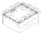
- FIG. 1 is a partially schematic isometric view of a spa according to one aspect of the present invention
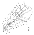
- FIG. 2 is an enlarged fragmentary view of a portion of the spa of FIG. 1 ;
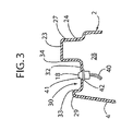
- FIG. 3 is a cross-sectional view of the spa taken along the line III-III; FIG. 2 ;
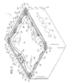
- FIG. 4 is a fragmentary, isometric view of a portion of the spa of FIG. 1 ;
- FIG. 5 is a fragmentary enlarged isometric view of a portion of the spa of FIG. 1 .
- the terms “upper,” “lower,” “right,” “left,” “rear,” “front,” “vertical,” “horizontal,” and derivatives thereof shall relate to the invention as oriented in FIG. 1 .
- the invention may assume various alternative orientations and step sequences, except where expressly specified to the contrary.
- the specific devices and processes illustrated in the attached drawings and described in the following specification are simply exemplary embodiments of the inventive concepts defined in the appended claims. Hence, specific dimensions and other physical characteristics relating to the embodiments disclosed herein are not to be considered as limiting, unless the claims expressly state otherwise.
- a spa system 1 includes a primary structure 2 having an outer side wall 3 having a generally quadrilateral shape in plan view.
- An inner side wall 4 forms a reservoir 5 that retains fluid such as water 6 .
- a plurality of water jets 7 are positioned in the seat areas 8 formed by inner side wall 4 .
- a pump 9 , heater 10 , filter 11 , and tubing system 12 provide pressurized water to the jets 7 and recirculate the water 6 in a known manner.
- the water jets 7 , pump 9 , heater 10 , filter 11 and tubing system 12 are conventional spa system components, such that these features will not be described in detail herein.
- the primary structure 2 has a polymer or fiber-reinforced construction of a type that is generally known to those skilled in the art.
- the spa system 1 also includes a plurality of speakers 13 that are operably connected to a receiver/CD player 14 .
- Each speaker 13 is mounted in a recessed area 15 at a corner 16 of the primary structure 2 , and one or more lights 18 are mounted in the recessed areas 15 adjacent speakers 13 .
- a plurality of recessed drink holders 17 are located in the upper portion 19 of primary structure 2 . As discussed in more detail below, each recessed drink holder 17 includes a light 18 and drain features to prevent retention of water in the drink holders 17 .
- the speakers 13 and receiver/CD player 14 are preferably marine-type components having reduced susceptibility to water and moisture damage.
- Inner side wall 4 includes a plurality of concave surfaces 25 forming a generally upright portion of the seat areas 8 .
- Vertical ridge surfaces 26 are formed between the concave surfaces 25 .
- a plurality of upwardly opening grooves or channels 30 extend along upper portions 31 of primary structure 2 .
- One or more upwardly-facing lights 18 are positioned in each groove or channel 30 .
- each groove or channel 30 includes a base surface 32 , and inner and outer side surfaces 33 and 34 , respectively.
- Inner side surfaces 33 is formed by a raised ridge 29
- outer side surface 34 is formed on the side of an outer wall section 27 having a generally horizontal upper surface 23 and an outer surface 24 .
- the primary structure 2 forms a cavity 28 for routing of wires 40 to lights 18 .
- the upwardly facing base surface 32 is a convex curved surface having a high center portion 35 and lower end portions 36 and 37 .
- the light 18 is mounted at the higher center portion 35 .
- the groove or channel 30 acts as a drain, and water that is splashed into groove or channel 30 drains away from the high center portion 35 towards the lower ends 36 and 37 , and out the ends 38 and 39 into the reservoir 5 of primary structure 2 .
- the height of the raised ridge 29 diminishes at the lower ends 36 and 37 of groove or channel 30 , and blends into the face surface 32 of groove or channel 30 at the ends 38 and 39 , such that water flows freely from the ends 38 and 39 into reservoir 5 .
- the lights 18 are mounted in the base surface 32 of grooves or channels 30 , and face upwardly.
- the raised ridge 29 substantially blocks the lights 18 from a direct line of sight to a seated user, thereby providing an indirect lighting effect.
- light from the lights 18 illuminates the outer side surface 34 , and thereby provides additional indirect lighting.
- Lights 18 are mounted in apertures 41 in base surface 32 , and a waterproof fitting 42 or the like prevents entry of water into the cavity 28 .
- speakers 13 are mounted in recessed areas 15 at corners 16 of primary structure 2 .
- Recessed area 15 includes a curved side wall surface 45 having a corner 46 .
- a light 18 is mounted in the side wall surface 45 at corner 46 , and faces outwardly away from the reservoir 5 .
- U-shaped drains 53 are formed between side walls 45 and end portions 54 of side wall surface 51 .
- the base surface 55 of U-shaped drains 53 is preferably lower than bottom surface 56 of recessed area 15 to thereby drain water out of recessed area 15 and away from speaker 13 .
- Upper surface 57 of outer ridge 50 is preferably at about the same height as upper surface 23 to provide a pleasing appearance, and also provide a generally flat upper surface for use by occupants of the spa system 1 .
- a cavity 60 with side walls 61 forms a recessed drink holder 17 .
- Side wall 61 has a generally circular shape in plan view, and includes a radiused upper edge 62 that smoothly blends into upper surface 23 of primary structure 2 .
- Ridges 64 and 65 extend upwardly from base surface 63 of cavity 60 and support a glass, can or the like above light 18 .
- Ridge 64 is preferably in the form of a step having an upper surface 66 that extends horizontally from the side surface 61 , and a generally vertical side surface 67 extending between the upper surface 66 and base surface 63 .
- Ridge 65 includes a generally vertical concave inner surface 68 , and a convex outer surface 69 and a generally flat upper surface 70 .
- Grooves or openings 58 and 59 are formed between the ridges 64 and 65 to provide drainage for water away from the light 18 .
- a light 18 is mounted in the face surface 63 proximate the center of cavity 60 .
- a channel 71 extends between the cavity 60 and reservoir 5 .
- Base surface 72 of channel 71 is preferably the same height or lower than the base surface 63 of cavity 60 , such that water drains from cavity 60 into reservoir 5 .
- a can, bottle, glass, or other such beverage container may be positioned in the drink holder 17 , with the drink being supported on the ridges 64 and 65 .
- the drink is held in place by the side surfaces 61 of cavity 60 .
- the raised ridges 64 and 65 provide a stable support surface for the drink, and hold the drink container in a position wherein the lower surface of the drink container is positioned above the light 18 .
- light 18 provides indirect lighting for users when a drink container is not positioned in the drink holder.
- the grooves 58 and 59 between the ridges 64 and 65 along with the channel 71 provide for drainage for water that is splashed into the cavity 60 of drink holder 17 back into reservoir 5 .
- drink holders 17 may be positioned in upper surface 23 of primary structure 2 in an area directly adjacent generally vertical ridges 73 adjacent concave surfaces 25 forming seating areas 8 .
- the speakers 13 are an optional feature of spa system 1 .
- the recessed area 15 at corners 16 may include a pair of raised ridges that are substantially similar to the ridges 64 and 65 of drink holder 17 .
- recessed area 15 forms a drink holder having a shape that is substantially similar to the drink holder 17 .
- the spa system 1 of the present invention includes a plurality of lights providing additional visual interest to users of the spa system 1 .
- a plurality of drains are configured to drain water away from the lights and speakers, while simultaneously providing an indirect lighting effect adjacent the lights. The drains for the lights blend smoothly into the seating areas of the spa, thereby contributing to the aesthetic appeal of the spa system 1 .
Landscapes
- Health & Medical Sciences (AREA)
- Public Health (AREA)
- Epidemiology (AREA)
- Pain & Pain Management (AREA)
- Physical Education & Sports Medicine (AREA)
- Rehabilitation Therapy (AREA)
- Life Sciences & Earth Sciences (AREA)
- Animal Behavior & Ethology (AREA)
- General Health & Medical Sciences (AREA)
- Veterinary Medicine (AREA)
- Arrangement Of Elements, Cooling, Sealing, Or The Like Of Lighting Devices (AREA)
Abstract
A spa system includes a reservoir having a side wall and a bottom defiling a spa cavity. The side all defines an upper portion heaving an upwardly-opening cavity. The upper portion of the side wall further includes a channel from the cavity providing drainage of fluid from the cavity. A fluid circulation system includes a powered pump and a plurality conduits connected to fluid outlets/jets in the spa cavity. The side wall includes at least one upwardly-opening channel above a waterline in the spa cavity. A light is positioned in the channel to provide indirect lighting for users of the spa system. The channel has an open portion configured to drain fluid splashed into the channel back into the spa cavity.
Description
- This application claims the benefit of U.S. Provisional Application No. 60/855,579, filed on Oct. 31, 2006, entitled SPA SYSTEM, the entire contents of which are incorporated by reference.
- Spas/hot tubs have been increasingly popular in recent years due to the relaxing and invigorating affect of spas. Spas typically include a tub-like structure configured to retain water and support one or more users in a seated or semi-reclined position. A plurality of jets provide a relaxing massage-type experience for the user. In addition to the pumps and jets and related components that provide for water movement, attempts have been made to include additional features such as sound systems and the like in spas to enhance the user's experience. However, the range of additional features has been somewhat limited.
- One aspect of the present invention is a spa system including a reservoir defining a generally upright side wall having inner and outer surfaces and a bottom portion closing off a bottom of the reservoir. The side wall and the bottom define an upwardly-opening spa cavity configured to retain fluid and to receive one or more users. The side wall defines an upper portion having an upwardly-opening cavity and a channel from the cavity providing drainage. The spa system further includes a fluid circulation system including a powered pump and a plurality of fluid outlets/jets in the spa cavity of the reservoir. A plurality of fluid conduits connect the powered pump to the fluid outlets. The side wall of the reservoir includes at least one upwardly-opening channel above a waterline in the spa cavity. The channel has an open portion that drains fluid splashed into the channel back into the cavity. An upwardly-facing light is positioned in the channel to provide indirect lighting for users of the spa system.
- These and other features, advantages, and objects of the present invention will be further understood and appreciated by those skilled in the art by reference to the following specification, claims, and appended drawings.
-
FIG. 1 is a partially schematic isometric view of a spa according to one aspect of the present invention; -
FIG. 2 is an enlarged fragmentary view of a portion of the spa ofFIG. 1 ; -
FIG. 3 is a cross-sectional view of the spa taken along the line III-III;FIG. 2 ; -
FIG. 4 is a fragmentary, isometric view of a portion of the spa ofFIG. 1 ; and -
FIG. 5 is a fragmentary enlarged isometric view of a portion of the spa ofFIG. 1 . - For purposes of description herein, the terms “upper,” “lower,” “right,” “left,” “rear,” “front,” “vertical,” “horizontal,” and derivatives thereof shall relate to the invention as oriented in
FIG. 1 . However, it is to be understood that the invention may assume various alternative orientations and step sequences, except where expressly specified to the contrary. It is also to be understood that the specific devices and processes illustrated in the attached drawings and described in the following specification are simply exemplary embodiments of the inventive concepts defined in the appended claims. Hence, specific dimensions and other physical characteristics relating to the embodiments disclosed herein are not to be considered as limiting, unless the claims expressly state otherwise. - With reference to
FIG. 1 , aspa system 1 according to one aspect of the present invention includes aprimary structure 2 having anouter side wall 3 having a generally quadrilateral shape in plan view. Aninner side wall 4 forms areservoir 5 that retains fluid such aswater 6. A plurality ofwater jets 7 are positioned in theseat areas 8 formed byinner side wall 4. Apump 9,heater 10,filter 11, andtubing system 12 provide pressurized water to thejets 7 and recirculate thewater 6 in a known manner. Thewater jets 7,pump 9,heater 10,filter 11 andtubing system 12 are conventional spa system components, such that these features will not be described in detail herein. Also, theprimary structure 2 has a polymer or fiber-reinforced construction of a type that is generally known to those skilled in the art. - The
spa system 1 also includes a plurality ofspeakers 13 that are operably connected to a receiver/CD player 14. Eachspeaker 13 is mounted in arecessed area 15 at acorner 16 of theprimary structure 2, and one ormore lights 18 are mounted in therecessed areas 15adjacent speakers 13. A plurality of recesseddrink holders 17 are located in theupper portion 19 ofprimary structure 2. As discussed in more detail below, each recesseddrink holder 17 includes alight 18 and drain features to prevent retention of water in thedrink holders 17. Thespeakers 13 and receiver/CD player 14 are preferably marine-type components having reduced susceptibility to water and moisture damage. -
Inner side wall 4 includes a plurality ofconcave surfaces 25 forming a generally upright portion of theseat areas 8.Vertical ridge surfaces 26 are formed between theconcave surfaces 25. A plurality of upwardly opening grooves orchannels 30 extend along upper portions 31 ofprimary structure 2. One or more upwardly-facinglights 18 are positioned in each groove orchannel 30. - With further reference to
FIGS. 2 and 3 , each groove orchannel 30 includes abase surface 32, and inner andouter side surfaces Inner side surfaces 33 is formed by a raisedridge 29, andouter side surface 34 is formed on the side of anouter wall section 27 having a generally horizontalupper surface 23 and anouter surface 24. Theprimary structure 2 forms acavity 28 for routing ofwires 40 tolights 18. The upwardly facingbase surface 32 is a convex curved surface having ahigh center portion 35 andlower end portions light 18 is mounted at thehigher center portion 35. The groove orchannel 30 acts as a drain, and water that is splashed into groove orchannel 30 drains away from thehigh center portion 35 towards thelower ends ends reservoir 5 ofprimary structure 2. The height of the raisedridge 29 diminishes at thelower ends channel 30, and blends into theface surface 32 of groove orchannel 30 at theends ends reservoir 5. - The
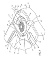
lights 18 are mounted in thebase surface 32 of grooves orchannels 30, and face upwardly. The raisedridge 29 substantially blocks thelights 18 from a direct line of sight to a seated user, thereby providing an indirect lighting effect. Also, light from thelights 18 illuminates theouter side surface 34, and thereby provides additional indirect lighting.Lights 18 are mounted inapertures 41 inbase surface 32, and awaterproof fitting 42 or the like prevents entry of water into thecavity 28. With further reference toFIG. 4 ,speakers 13 are mounted inrecessed areas 15 atcorners 16 ofprimary structure 2. Recessedarea 15 includes a curvedside wall surface 45 having acorner 46. Alight 18 is mounted in theside wall surface 45 atcorner 46, and faces outwardly away from thereservoir 5. Thus,light 18 atcorner 16 is substantially blocked from direct view by a seated user by the raisedridge 47 formed between thecorner 46 ofside wall 45 andconcave surface 25. Anouter ridge 50 is formed betweenside wall surface 51 andouter surface 52 ofprimary structure 2 atcorner 16. U-shapeddrains 53 are formed betweenside walls 45 andend portions 54 ofside wall surface 51. Thebase surface 55 of U-shapeddrains 53 is preferably lower thanbottom surface 56 ofrecessed area 15 to thereby drain water out ofrecessed area 15 and away fromspeaker 13.Upper surface 57 ofouter ridge 50 is preferably at about the same height asupper surface 23 to provide a pleasing appearance, and also provide a generally flat upper surface for use by occupants of thespa system 1. - With further reference to
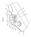
FIG. 5 , acavity 60 withside walls 61 forms a recesseddrink holder 17.Side wall 61 has a generally circular shape in plan view, and includes a radiusedupper edge 62 that smoothly blends intoupper surface 23 ofprimary structure 2.Ridges base surface 63 ofcavity 60 and support a glass, can or the like abovelight 18.Ridge 64 is preferably in the form of a step having anupper surface 66 that extends horizontally from theside surface 61, and a generallyvertical side surface 67 extending between theupper surface 66 andbase surface 63.Ridge 65 includes a generally vertical concaveinner surface 68, and a convexouter surface 69 and a generally flatupper surface 70. Grooves oropenings ridges face surface 63 proximate the center ofcavity 60. Achannel 71 extends between thecavity 60 andreservoir 5.Base surface 72 ofchannel 71 is preferably the same height or lower than thebase surface 63 ofcavity 60, such that water drains fromcavity 60 intoreservoir 5. - In use, a can, bottle, glass, or other such beverage container may be positioned in the
drink holder 17, with the drink being supported on theridges cavity 60. The raisedridges grooves ridges channel 71 provide for drainage for water that is splashed into thecavity 60 ofdrink holder 17 back intoreservoir 5. Still further, with reference back toFIG. 1 , drinkholders 17 may be positioned inupper surface 23 ofprimary structure 2 in an area directly adjacent generallyvertical ridges 73 adjacentconcave surfaces 25 formingseating areas 8. - With reference to
FIGS. 4 and 5 , thespeakers 13 are an optional feature ofspa system 1. The recessedarea 15 atcorners 16 may include a pair of raised ridges that are substantially similar to theridges drink holder 17. Thus, ifspa system 1 is configured withoutspeakers 13, recessedarea 15 forms a drink holder having a shape that is substantially similar to thedrink holder 17. - The
spa system 1 of the present invention includes a plurality of lights providing additional visual interest to users of thespa system 1. A plurality of drains are configured to drain water away from the lights and speakers, while simultaneously providing an indirect lighting effect adjacent the lights. The drains for the lights blend smoothly into the seating areas of the spa, thereby contributing to the aesthetic appeal of thespa system 1. - In the foregoing description, it will be readily appreciated by those skilled in the art that modifications may be made to the invention without departing from the concepts disclosed herein. Such modifications are to be considered as included in the following claims, unless these claims by their language expressly state otherwise.
Claims (19)
1. A spa system, comprising:
a reservoir defining a generally upright side wall having inner and outer surfaces and a bottom portion closing off a bottom of the reservoir, the side wall and the bottom defining an upwardly-opening spa cavity configured to retain fluid and receive one or more users;
a fluid circulation system including a powered pump and a plurality of fluid outlets in the spa cavity of the reservoir, and a plurality fluid conduits fluidly connecting the powered pump to the fluid outlets;
the side wall including at least one upwardly opening channel above a waterline in the spa cavity, the channel having an open portion configured to drain fluid from the channel into the cavity; and
a light positioned in the channel to provide lighting for users of the spa system.
2. The spa system of claim 1 , wherein:
the side wall defines an upper edge, and the channel is positioned adjacent the upper edge of the side wall.
3. The spa system of claim 2 , wherein:
the inner Surface of the side wall includes a step-like portion with an upwardly facing surface that forms the channel.
4. The spa system of claim 3 , wherein:
the channel includes a central portion and opposite end portions, wherein the central portion is higher than the opposite end portions such that water drains from the central portion to the opposite end portions.
5. The spa system of claim 4 , wherein:
the light is positioned in the central portion of the channel.
6. The spa system of claim 1 , wherein:
the channel includes a base surface and side surfaces having a generally U-shaped cross-sectional profile.
7. The spa system of claim 6 , wherein:
the light is mounted to the base surface and faces upwardly.
8. The spa system of claim 1 , wherein:
the light defines a light-transmitting outer surface;
a side wall of the channel extends upwardly adjacent the light and defines an upper edge, wherein the upper edge is above the light-transmitting outer surface of the light.
9. The spa system of claim 1 , wherein:
the side wall has four straight portions defining a generally quadrilateral shape in plan view, and wherein:
each straight portion includes at least one upwardly-opening channel and a light positioned in each channel.
10. The spa system of claim 1 , wherein:
the side wall defines an upwardly facing surface having at least one upwardly opening beverage-retaining cavity having a lower surface, the lower surface having an upwardly extending portion, and including:
at least one light in the cavity proximate the upwardly extending portion of the lower surface.
11. The spa system of claim 10 , wherein:
the light defines an outer surface, and the upwardly extending portion of the lower surface is above the outer surface of the light.
12. The spa system of claim 10 , wherein:
the beverage-retaining cavity has side walls having a generally cylindrical inner surface.
13. The spa system of claim 12 , wherein:
the side wall includes at least one upwardly-opening channel therethrough to the spa cavity to provide drainage for the beverage-retaining channel.
14. A spa system, comprising:
a reservoir defining a generally upright side wall having inner and outer surfaces and a bottom portion closing off a bottom of the reservoir, the side wall and the bottom defining an upwardly-opening spa cavity configured to retain fluid and receive one or more users;
the side wall defines an upper portion having an upwardly-opening cavity and a channel from the cavity and providing drainage of fluid from the cavity; and
a fluid circulation system including a powered pump and a plurality of fluid outlets in the spa cavity of the reservoir, and a plurality fluid conduits fluidly connecting the powered pump to the fluid outlets;
an audio speaker positioned in the cavity.
15. The spa system of claim 14 , wherein:
the audio speaker comprises a first audio speaker;
the side wall has a generally quadrilateral shape in plan view and includes four corners, each including an upwardly-opening cavity and a drainage channel; and including:
an audio speaker positioned in each of the upwardly-opening cavities.
16. The spa system of claim 15 , wherein:
the upwardly-opening cavity defines a bottom surface, and the channels define lower surfaces that are below the bottom surfaces of the upwardly-opening cavities.
17. The spa system of claim 15 , wherein:
at least one of the channels extends from the upwardly-opening cavity to the outer surface of the side wall of the reservoir to drain fluid out of the spa system.
18. The spa system of claim 15 , wherein:
each corner includes two drainage channels extending from the upwardly-opening cavities to the outer surface of the side wall of the reservoir.
19. A method of making a spa system, comprising:
providing a plurality of spa tubs, each having a side wall with an upper edge having an upwardly-opening cavity and a drainage channel extending from the cavity, each upwardly-opening cavity having a bottom surface having an upwardly extending portion;
providing a plurality of audio speakers;
mounting audio speakers in some of the upwardly-opening cavities.
Priority Applications (1)
| Application Number | Priority Date | Filing Date | Title |
|---|---|---|---|
| US11/930,803 US20080098509A1 (en) | 2006-10-31 | 2007-10-31 | Spa System |
Applications Claiming Priority (2)
| Application Number | Priority Date | Filing Date | Title |
|---|---|---|---|
| US85557906P | 2006-10-31 | 2006-10-31 | |
| US11/930,803 US20080098509A1 (en) | 2006-10-31 | 2007-10-31 | Spa System |
Publications (1)
| Publication Number | Publication Date |
|---|---|
| US20080098509A1 true US20080098509A1 (en) | 2008-05-01 |
Family
ID=39328385
Family Applications (1)
| Application Number | Title | Priority Date | Filing Date |
|---|---|---|---|
| US11/930,803 Abandoned US20080098509A1 (en) | 2006-10-31 | 2007-10-31 | Spa System |
Country Status (1)
| Country | Link |
|---|---|
| US (1) | US20080098509A1 (en) |
Cited By (6)
| Publication number | Priority date | Publication date | Assignee | Title |
|---|---|---|---|---|
| US20090172873A1 (en) * | 2007-11-07 | 2009-07-09 | Ludlow David J | Spa construction and installation system |
| USD735347S1 (en) * | 2012-10-24 | 2015-07-28 | MAAX Spas Industries Corporation | Spa ledge with spill sill |
| US9140419B2 (en) * | 2013-11-12 | 2015-09-22 | Custom Molded Products, Inc. | Lighted cup holder and lighting method |
| US9247362B2 (en) | 2011-01-11 | 2016-01-26 | Coast Spas Manufacturing Inc. | Hands-free cellular telephone enabled spa |
| US9603496B1 (en) * | 2013-03-15 | 2017-03-28 | David C. Hartman | Toilet seat assembly |
| US10969095B2 (en) | 2017-04-10 | 2021-04-06 | Masterspas, Llc | Lighting system and method |
Citations (15)
| Publication number | Priority date | Publication date | Assignee | Title |
|---|---|---|---|---|
| US3579667A (en) * | 1969-06-05 | 1971-05-25 | Gino Giglio | Bathtub construction |
| US4575882A (en) * | 1985-01-18 | 1986-03-18 | Diamond Harvey E | Integrated stereo and bathtub system II |
| USD301374S (en) * | 1986-12-01 | 1989-05-30 | Jacuzzi Inc. | Whirlpool-Spa |
| US5045978A (en) * | 1989-06-05 | 1991-09-03 | Gargle Benjamin H | Underwater lighting fixture |
| USD454643S1 (en) * | 2001-06-20 | 2002-03-19 | Nordic Products, Inc. | Hot tub |
| US6360380B1 (en) * | 2000-08-07 | 2002-03-26 | Kohler Co. | Overflowing soaker bath tub |
| US20030154544A1 (en) * | 2002-02-19 | 2003-08-21 | 513004 B. C. Ltd. | Negative or vanishing edge for spas and/or hot tubs |
| US6754916B1 (en) * | 2002-10-18 | 2004-06-29 | Saratoga Spa & Bath, Inc. | Spas having a retractable entertainment unit |
| US6763532B2 (en) * | 2001-04-12 | 2004-07-20 | Saratoga Spa & Bath, Inc. | Head rest assembly having an illuminated insert for a spa |
| US6775863B2 (en) * | 2002-10-23 | 2004-08-17 | Dimension One Spas | Spa or pool switch |
| USD499809S1 (en) * | 2003-04-07 | 2004-12-14 | Mti Whirlpools, Inc. | Water bath tub |
| USD512780S1 (en) * | 2004-08-23 | 2005-12-13 | Casey Loyd | Spa shell |
| US7055186B2 (en) * | 2001-11-06 | 2006-06-06 | Master Spas, Inc. | Combination spa and entertainment system |
| US7293300B2 (en) * | 2004-04-21 | 2007-11-13 | Watkins Manufacturing Corporation | Trickle waterfall for spa |
| US7814583B2 (en) * | 2003-09-04 | 2010-10-19 | B & S Plastics, Inc. | Retractable rotating spa speaker system |
-
2007
- 2007-10-31 US US11/930,803 patent/US20080098509A1/en not_active Abandoned
Patent Citations (15)
| Publication number | Priority date | Publication date | Assignee | Title |
|---|---|---|---|---|
| US3579667A (en) * | 1969-06-05 | 1971-05-25 | Gino Giglio | Bathtub construction |
| US4575882A (en) * | 1985-01-18 | 1986-03-18 | Diamond Harvey E | Integrated stereo and bathtub system II |
| USD301374S (en) * | 1986-12-01 | 1989-05-30 | Jacuzzi Inc. | Whirlpool-Spa |
| US5045978A (en) * | 1989-06-05 | 1991-09-03 | Gargle Benjamin H | Underwater lighting fixture |
| US6360380B1 (en) * | 2000-08-07 | 2002-03-26 | Kohler Co. | Overflowing soaker bath tub |
| US6763532B2 (en) * | 2001-04-12 | 2004-07-20 | Saratoga Spa & Bath, Inc. | Head rest assembly having an illuminated insert for a spa |
| USD454643S1 (en) * | 2001-06-20 | 2002-03-19 | Nordic Products, Inc. | Hot tub |
| US7055186B2 (en) * | 2001-11-06 | 2006-06-06 | Master Spas, Inc. | Combination spa and entertainment system |
| US20030154544A1 (en) * | 2002-02-19 | 2003-08-21 | 513004 B. C. Ltd. | Negative or vanishing edge for spas and/or hot tubs |
| US6754916B1 (en) * | 2002-10-18 | 2004-06-29 | Saratoga Spa & Bath, Inc. | Spas having a retractable entertainment unit |
| US6775863B2 (en) * | 2002-10-23 | 2004-08-17 | Dimension One Spas | Spa or pool switch |
| USD499809S1 (en) * | 2003-04-07 | 2004-12-14 | Mti Whirlpools, Inc. | Water bath tub |
| US7814583B2 (en) * | 2003-09-04 | 2010-10-19 | B & S Plastics, Inc. | Retractable rotating spa speaker system |
| US7293300B2 (en) * | 2004-04-21 | 2007-11-13 | Watkins Manufacturing Corporation | Trickle waterfall for spa |
| USD512780S1 (en) * | 2004-08-23 | 2005-12-13 | Casey Loyd | Spa shell |
Cited By (7)
| Publication number | Priority date | Publication date | Assignee | Title |
|---|---|---|---|---|
| US20090172873A1 (en) * | 2007-11-07 | 2009-07-09 | Ludlow David J | Spa construction and installation system |
| US8881321B1 (en) * | 2007-11-07 | 2014-11-11 | Bullfrog International, L.C. | Spa construction and installation system |
| US9247362B2 (en) | 2011-01-11 | 2016-01-26 | Coast Spas Manufacturing Inc. | Hands-free cellular telephone enabled spa |
| USD735347S1 (en) * | 2012-10-24 | 2015-07-28 | MAAX Spas Industries Corporation | Spa ledge with spill sill |
| US9603496B1 (en) * | 2013-03-15 | 2017-03-28 | David C. Hartman | Toilet seat assembly |
| US9140419B2 (en) * | 2013-11-12 | 2015-09-22 | Custom Molded Products, Inc. | Lighted cup holder and lighting method |
| US10969095B2 (en) | 2017-04-10 | 2021-04-06 | Masterspas, Llc | Lighting system and method |
Similar Documents
| Publication | Publication Date | Title |
|---|---|---|
| US20080098509A1 (en) | Spa System | |
| USD504609S1 (en) | Pivoting curtain rod support | |
| USD533251S1 (en) | Dual symmetrical head adjustable shower fitting | |
| USD568485S1 (en) | Pedicure spa | |
| USD511201S1 (en) | Faucet | |
| USD505831S1 (en) | Resealable tumbler | |
| USD521098S1 (en) | Water bowl ride exit flume | |
| USD489795S1 (en) | Faucet | |
| USD531454S1 (en) | Mug | |
| USD594925S1 (en) | Accessory rail mount for vertical foregrip | |
| USD603486S1 (en) | Vessel | |
| USD478750S1 (en) | Shower chair | |
| USD607079S1 (en) | Rail mount for vertical fore grips | |
| USD517648S1 (en) | Faucet | |
| USD495506S1 (en) | Shower seat | |
| USD514201S1 (en) | Faucet | |
| USD575406S1 (en) | Water spa | |
| USD530154S1 (en) | Mug | |
| USD510487S1 (en) | Shower seat | |
| USD494767S1 (en) | Shower seat | |
| USD566220S1 (en) | Bipod | |
| USD517649S1 (en) | Faucet | |
| USD478752S1 (en) | Shower chair seat | |
| USD591976S1 (en) | Vanity | |
| USD512124S1 (en) | Faucet |
Legal Events
| Date | Code | Title | Description |
|---|---|---|---|
| AS | Assignment |
Owner name: VIKING SPAS, INC., MICHIGAN Free format text: ASSIGNMENT OF ASSIGNORS INTEREST;ASSIGNORS:KANTOR, PAUL;WOOD, RODNEY J;KNEESHAW, THOMAS M;REEL/FRAME:020043/0502 Effective date: 20071025 |
|
| STCB | Information on status: application discontinuation |
Free format text: ABANDONED -- FAILURE TO RESPOND TO AN OFFICE ACTION |