US20080098146A1 - Interrupt hooking method for a computing apparatus - Google Patents
Interrupt hooking method for a computing apparatus Download PDFInfo
- Publication number
- US20080098146A1 US20080098146A1 US11/583,927 US58392706A US2008098146A1 US 20080098146 A1 US20080098146 A1 US 20080098146A1 US 58392706 A US58392706 A US 58392706A US 2008098146 A1 US2008098146 A1 US 2008098146A1
- Authority
- US
- United States
- Prior art keywords
- interrupt
- processing device
- controller
- application program
- operating mode
- Prior art date
- Legal status (The legal status is an assumption and is not a legal conclusion. Google has not performed a legal analysis and makes no representation as to the accuracy of the status listed.)
- Abandoned
Links
Images


Classifications
-
- G—PHYSICS
- G06—COMPUTING OR CALCULATING; COUNTING
- G06F—ELECTRIC DIGITAL DATA PROCESSING
- G06F13/00—Interconnection of, or transfer of information or other signals between, memories, input/output devices or central processing units
- G06F13/14—Handling requests for interconnection or transfer
- G06F13/20—Handling requests for interconnection or transfer for access to input/output bus
- G06F13/24—Handling requests for interconnection or transfer for access to input/output bus using interrupt
Definitions
- This invention relates to an interrupt hooking method for a computing apparatus, more particularly to an interrupt hooking method for a computing apparatus that permits servicing of a system control interrupt (SCI) by a customized interrupt handler.
- SCI system control interrupt
- ACPI advanced configuration and power management interface
- SCI system control interrupt
- OS operating system
- U.S. Patent Application Publication No. 2005/0138256 there is disclosed a conventional method that permits generation of the ACPI SCI through a hotkey using an operating system visible interrupt.
- the ACPI SCI can be serviced only by predefined interrupt handlers of the ACPI.
- the object of the present invention is to provide an interrupt hooking method that can overcome the aforesaid drawback of the prior art.
- an interrupt hooking method for a computing apparatus which includes a processing device and an interrupt controller, comprises the steps of:
- IRQ hardware interrupt request
- SCI system control interrupt
- step b) through the application program, enabling the processing device to modify a pointer in an interrupt descriptor table, which points to locations of interrupt handlers, that corresponds to the predefined interrupt vector obtained in step a) for directing to a corresponding interrupt handler of the application program.
- a computing apparatus comprises a processing device, and an interrupt controller that is coupled to the processing device.
- the processing device has an interrupt descriptor table for pointing to locations of interrupt handlers, and is configured to launch an application program.
- the processing device is configured by the application program to convert a hardware interrupt request (IRQ) number of a system control interrupt (SCI) into a predefined interrupt vector according to an operating mode of the interrupt controller, and to modify a pointer in the interrupt descriptor table that corresponds to the predefined interrupt vector for directing to a corresponding interrupt handler of the application program.
- IRQ hardware interrupt request
- SCI system control interrupt
- FIG. 1 is a schematic block diagram of the first preferred embodiment of a computing apparatus according to this invention.
- FIG. 2 is a schematic view to illustrate the computing apparatus of the first embodiment including three advanced programmable interrupt controllers;
- FIGS. 3A to 3E are flowcharts of the preferred embodiment of an interrupt hooking method for the computing apparatus of the first embodiment according to this invention.
- FIG. 4 is a schematic block diagram of the second preferred embodiment of a computing apparatus according to this invention.
- the first preferred embodiment of a computing apparatus 1 includes a processing device 11 and an interrupt controller 12 .
- the computing apparatus 1 supports the IA32 platform Intel architecture, and uses a power management, which complies with an Advanced Configuration and Power Management Interface (ACPI).
- ACPI Advanced Configuration and Power Management Interface
- the computing apparatus 1 supports the IA64 Intel architecture.
- the processing device 11 of the computing apparatus 1 is configured to launch an application program, and has an interrupt descriptor table (IDT) that includes two hundred and fifty-six descriptors, each of which includes a pointer that points to a location of a respective one of operating system interrupt handlers.
- IDT interrupt descriptor table
- the interrupt controller 12 is coupled to the processing device 11 and has an operating mode.
- the operating mode of the interrupt controller 12 may be one of a programmable interrupt controller (PIC) operating mode and an advanced programmable interrupt controller (APIC) operating mode.
- PIC programmable interrupt controller
- APIC advanced programmable interrupt controller
- the application program includes an interrupt hooking table, and an interrupt handler, which is also known as an interrupt service routine (ISR).
- ISR interrupt service routine
- the interrupt hooking table of the application program includes an interrupt event that corresponds to the interrupt handler of the application program, and a plurality of entries, one of which records a relation between the interrupt event and the corresponding interrupt handler of the application program.
- the processing device 11 is configured by the application program to convert a hardware interrupt request (IRQ) number, which is also known as a global system interrupt (GSINT) number, of a system control interrupt (SCI) into a predefined interrupt vector according to the operating mode of the interrupt controller 12 , and to modify the pointer in one of the descriptors of the interrupt descriptor table that corresponds to the predefined interrupt vector for directing to a corresponding interrupt handler of the application program, in a manner that will be described in greater detail hereinafter.
- IRQ hardware interrupt request
- GSINT global system interrupt
- SCI system control interrupt
- the computing apparatus 1 further includes a basic input output system (BIOS) 13 that is coupled to the processing device 11 , and that has an Advanced Configuration and Power Management Interface (ACPI) table, specifically, the fixed ACPI description table (FADT), from which the IRQ number of the SCI is obtained.
- BIOS basic input output system
- ACPI Advanced Configuration and Power Management Interface
- FADT fixed ACPI description table
- the IRQ number is converted into the predefined interrupt vector according to an operating system when the operating mode of the interrupt controller 12 is the PIC operating mode. That is, when the operating system is a disk operating system (DOS), the processing device 11 converts the IRQ number into the predefined interrupt vector using a first conversion algorithm. It is noted that, in DOS, IRQ numbers 0 through 7 correspond to predefined interrupt vectors 8 h through Fh, respectively, and IRQ numbers 8 through 15 correspond to predefined interrupt vectors 70 h through 77 h, respectively. On the other hand, when the operating system is a windows operating system (OS), the processing device 11 converts the IRQ number into the predefined interrupt vector using a second conversion algorithm. It is noted that, in windows OS, IRQ numbers 0 to 15 correspond to predefined interrupt vectors 30 h to 3 F h, respectively.
- OS windows operating system
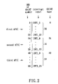
- the IRQ number is converted into the predefined interrupt vector according to the ACPI table and register information in a maximum redirection entry register of the interrupt controller 12 when the operating mode of the interrupt controller 12 is the APIC operating mode. That is, the processing device 11 first obtains a GSINT base from the ACPI table and a number of interrupt inputs of the interrupt controller 12 from the maximum redirection entry register of the interrupt controller 12 . Then, the processing device 11 converts the IRQ number into the predefined interrupt vector according to the GSINT base and the number of interrupt inputs of the interrupt controller 12 , through an I/O redirection table (IOREDTBL) of the interrupt controller 12 . It is noted that the IOREDTBL has twenty-four registers (IOREDTBL 0 through IOREDTBL 23 ), one of which includes the predefined interrupt vector.
- the computing apparatus 1 includes three of the APIC, namely first APIC, second APIC and third APIC.
- an APIC can support a maximum of twenty-four interrupt inputs.
- the first, second and third APICs are implemented to support twenty-four, sixteen and twenty-four interrupt inputs, respectively.
- the GSINT bases that can be obtained from the FADT table are, therefore, 0, 24, and 40, and the numbers of interrupt inputs that can obtained from the maximum redirection entry register of the APIC are, therefore, 24, 16, and 24.
- the IRQ number can then be converted into the predefined interrupt vector by looking up the IOREDTBL referred by one of the obtained GSINT bases and one of the obtained numbers of the interrupt inputs.
- the computing apparatus 1 further includes a system memory 14 that is coupled to the processing device 11 .
- the preferred embodiment of an interrupt hooking method for the aforementioned computing apparatus 1 according to this invention includes the steps shown in FIG. 3A .
- step 31 through the application program, the processing device 11 determines a version of the power management used by the computing apparatus 1 .
- step 31 includes the sub-steps shown in FIG. 3B :
- Sub-step 311 the processing device 11 looks for a root system description pointer (RSDP) table in an extended BIOS data area (EBDA) of the system memory 14 of the computing apparatus 1 .
- RSDP root system description pointer
- EBDA extended BIOS data area
- Sub-step 312 when the processing device 11 finds the RSDP table in the EBDA of the system memory 14 of the computing apparatus 1 , the flow proceeds to sub-step 314 . Otherwise, when the processing device 11 does not find the RSDP table in the EBDA of the system memory 14 of the computing apparatus 1 , the flow proceeds to sub-step 313 .
- Sub-step 313 the processing device 11 looks for the RSDP table in the memory addresses E 0000 to FFFFFh of the system memory 14 of the computing apparatus 1 . Thereafter, the flow proceeds to sub-step 314 .
- Sub-step 314 the processing device 11 searches a string “RSD PTR” in the RSDP table.
- Sub-step 315 when the processing device 11 finds the string “RSD PTR” in the RSDP table, which indicates that the version of the power management used by the computing apparatus 1 complies with an ACPI 1.0 or later specification, the flow proceeds to step 32 . Otherwise, when the processing device 11 does not find the string “RSD PTR” in the RSDP table, which indicates that the version of the power management used by the computing apparatus 1 does not comply with the ACPI 1.0 or later specification, the flow proceeds to step 38 .
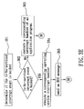
- step 32 through the application program, the processing device 11 converts the IRQ number of the SCI into the predefined interrupt vector according to an operating mode of the interrupt controller 12 .
- step 32 includes the sub-steps shown in FIG. 3C :
- Sub-step 321 the processing device 11 looks for the ACPI table, i.e., the FADT, by searching the string “FACP” in the BIOS 13 of the computing apparatus 1 .
- Sub-step 322 the processing device 11 obtains the IRQ number of the SCI from the ACPI table of the BIOS 13 of the computing apparatus 1 .
- Sub-step 323 the processing device 11 reads the 11 th bit of an IA32_APIC_BASE machine specific register thereof.
- Sub-step 324 when the 11 th bit of the IA32_APIC_BASE machine specific register is a logic “0”, which indicates that the operating mode of the interrupt controller 12 is the PIC operating mode, the flow proceeds to sub-step 325 . Otherwise, the 11 th bit of the IA32_APIC_BASE machine specific register is, therefore, a logic “1”, which indicates that the operating mode of the interrupt controller 12 is the APIC operating mode, and the flow proceeds to sub-step 330 .
- Sub-step 325 the processing device 11 determines the operating system.
- Sub-step 326 when the operating system is determined in sub-step 325 to be the disk operating system (DOS), the flow proceeds to sub-step 328 . Otherwise, the flow proceeds to sub-step 327 .
- DOS disk operating system
- Sub-step 327 when the operating system is determined in sub-step 325 to the windows OS, the flow proceeds to sub-step 329 . Otherwise, the flow proceeds to step 38 .
- Sub-step 328 the processing device 11 converts the IRQ number of the SCI obtained in sub-step 322 into the predefined interrupt vector using the first conversion algorithm. Thereafter, the flow proceeds to step 34 .
- Sub-step 329 the processing device 11 converts the IRQ number of the SCI obtained in sub-step 322 into the predefined interrupt vector using the second conversion algorithm. Thereafter, the flow proceeds to step 34 .
- Sub-step 330 the processing device 11 obtains the GSINT base from the ACPI table of the BIOS 13 of the computing apparatus 1 .
- Sub-step 331 the processing device 11 obtains the number of interrupt inputs of the APIC from the maximum redirection entry register of the APIC.
- Sub-step 332 the processing device 11 converts the IRQ number into the predefined interrupt vector according to the GSINT base obtained in sub-step 329 and the number of interrupt inputs of the interrupt controller 12 obtained in sub-step 330 through the IOREDTBL of the interrupt controller 12 . Thereafter, the flow proceeds to step 34 .
- step 34 through the application program, the processing device 11 modifies the pointer of the descriptor of the interrupt descriptor table (IDT) that corresponds to the predefined interrupt vector obtained in step 32 for directing to the corresponding interrupt handler of the application program.
- IDT interrupt descriptor table
- step 34 includes the sub-steps shown in FIG. 3D :
- Sub-step 341 the processing device 11 obtains the address of the IDT by executing the command, SIDT (save IDT).
- Sub-step 342 the processing device 11 determines the descriptor in the IDT that corresponds to the predefined interrupt vector obtained in step 32 .
- Sub-step 343 the processing device 11 modifies the pointer of the descriptor in the IDT. Thereafter, the flow proceeds to step 35 .
- step 35 the processing device 11 initializes an interrupt event that corresponds to the IRQ number with reference to initialization information in the interrupt hooking table of the application program. Thereafter, the flow proceeds to step 36 .
- initialization information can be used to add, delete, enable or disable the interrupt events.
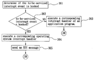
- step 36 in response to a to-be-serviced interrupt event, the processing device 11 services the to-be-serviced interrupt event.
- step 36 includes the sub-steps shown in FIG. 3E :
- Sub-step 361 an interrupt processor of the processing device 11 determines if the to-be-serviced interrupt event is the interrupt event hooked by the application program by polling the entries of the interrupt hooking table.
- Sub-step 362 when the to-be-serviced interrupt event is determined in sub-step 361 to be not the interrupt event hooked by the application program, the flow proceeds to sub-step 363 . Otherwise, when the to-be-serviced interrupt event is determined in sub-step 361 to be the interrupt event hooked by the application program, the flow proceeds to step 364 .
- Sub-step 363 the interrupt processor of the processing device 11 executes a corresponding operating system interrupt handler. Thereafter, the flow proceeds to step 38 .
- Sub-step 364 the interrupt processor of the processing device 11 executes the corresponding interrupt handler of the application program.
- Sub-step 365 the processing device 11 sends an end of interrupt (EOI) message to the interrupt controller 12 after servicing the to-be serviced interrupt event. Thereafter, the flow proceeds to step 38 .
- EAI end of interrupt
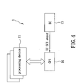
- FIG. 4 illustrates the second preferred embodiment of a computing apparatus 1 according to this invention.
- the computing apparatus 1 is a notebook computer, and further includes a General Purpose Interface (GPI) 16 that is coupled the processing device 11 , and an embedded controller (EC) 14 that is coupled to the GPI 16 .
- GPI General Purpose Interface
- EC embedded controller
- the processing device 11 sends an EC SCI event to the processing device 11 through the GPI 16 .
- the processing device 11 through the application program, executes an EC command to obtain an EC code to determine if the EC interrupt event is the interrupt event hooked by the application program.
- the EC interrupt event is serviced by the interrupt handler of the application program.
- the EC interrupt event is serviced by an operating system power management (OSPM). In this case, the EC code is “pushed back” to a polling pool of the EC 14 .
- OSPM operating system power management
Landscapes
- Engineering & Computer Science (AREA)
- Theoretical Computer Science (AREA)
- Physics & Mathematics (AREA)
- General Engineering & Computer Science (AREA)
- General Physics & Mathematics (AREA)
- Stored Programmes (AREA)
Abstract
An interrupt hooking method for a computing apparatus, which includes a processing device and an interrupt controller, includes the steps of: enabling the processing device to convert a hardware interrupt request (IRQ) number of a system control interrupt (SCI) into a predefined interrupt vector according to an operating mode of the interrupt controller; and enabling the processing device to modify a pointer in an interrupt descriptor table that corresponds to the predefined interrupt vector for directing to a corresponding interrupt handler of the application program. A computing apparatus, which includes the processing device that performs the interrupt hooking method, is also disclosed.
Description
- 1. Field of the Invention
- This invention relates to an interrupt hooking method for a computing apparatus, more particularly to an interrupt hooking method for a computing apparatus that permits servicing of a system control interrupt (SCI) by a customized interrupt handler.
- 2. Description of the Related Art
- An advanced configuration and power management interface (ACPI) system control interrupt (SCI) is typically generated by an operating system (OS) of a computing apparatus. In U.S. Patent Application Publication No. 2005/0138256, however, there is disclosed a conventional method that permits generation of the ACPI SCI through a hotkey using an operating system visible interrupt.
- Although the aforementioned conventional method achieves its intended purpose, the ACPI SCI can be serviced only by predefined interrupt handlers of the ACPI.
- Therefore, the object of the present invention is to provide an interrupt hooking method that can overcome the aforesaid drawback of the prior art.
- According to one aspect of the present invention, an interrupt hooking method for a computing apparatus, which includes a processing device and an interrupt controller, comprises the steps of:
- a) through an application program, which is launched by the processing device, enabling the processing device to convert a hardware interrupt request (IRQ) number of a system control interrupt (SCI) into a predefined interrupt vector according to an operating mode of the interrupt controller; and
- b) through the application program, enabling the processing device to modify a pointer in an interrupt descriptor table, which points to locations of interrupt handlers, that corresponds to the predefined interrupt vector obtained in step a) for directing to a corresponding interrupt handler of the application program.
- According to another aspect of the present invention, a computing apparatus comprises a processing device, and an interrupt controller that is coupled to the processing device. The processing device has an interrupt descriptor table for pointing to locations of interrupt handlers, and is configured to launch an application program. The processing device is configured by the application program to convert a hardware interrupt request (IRQ) number of a system control interrupt (SCI) into a predefined interrupt vector according to an operating mode of the interrupt controller, and to modify a pointer in the interrupt descriptor table that corresponds to the predefined interrupt vector for directing to a corresponding interrupt handler of the application program.
- Other features and advantages of the present invention will become apparent in the following detailed description of the preferred embodiments with reference to the accompanying drawings, of which:
-
FIG. 1 is a schematic block diagram of the first preferred embodiment of a computing apparatus according to this invention; -
FIG. 2 is a schematic view to illustrate the computing apparatus of the first embodiment including three advanced programmable interrupt controllers; -
FIGS. 3A to 3E are flowcharts of the preferred embodiment of an interrupt hooking method for the computing apparatus of the first embodiment according to this invention; and -
FIG. 4 is a schematic block diagram of the second preferred embodiment of a computing apparatus according to this invention. - Before the present invention is described in greater detail, it should be noted that like elements are denoted by the same reference numerals throughout the disclosure.
- Referring to
FIG. 1 , the first preferred embodiment of acomputing apparatus 1 according to this invention includes aprocessing device 11 and aninterrupt controller 12. - In this embodiment, the
computing apparatus 1 supports the IA32 platform Intel architecture, and uses a power management, which complies with an Advanced Configuration and Power Management Interface (ACPI). In an alternative embodiment, thecomputing apparatus 1 supports the IA64 Intel architecture. - The
processing device 11 of thecomputing apparatus 1 is configured to launch an application program, and has an interrupt descriptor table (IDT) that includes two hundred and fifty-six descriptors, each of which includes a pointer that points to a location of a respective one of operating system interrupt handlers. - The
interrupt controller 12 is coupled to theprocessing device 11 and has an operating mode. In this embodiment, the operating mode of theinterrupt controller 12 may be one of a programmable interrupt controller (PIC) operating mode and an advanced programmable interrupt controller (APIC) operating mode. - The application program includes an interrupt hooking table, and an interrupt handler, which is also known as an interrupt service routine (ISR). In this embodiment, the interrupt hooking table of the application program includes an interrupt event that corresponds to the interrupt handler of the application program, and a plurality of entries, one of which records a relation between the interrupt event and the corresponding interrupt handler of the application program.
- The
processing device 11 is configured by the application program to convert a hardware interrupt request (IRQ) number, which is also known as a global system interrupt (GSINT) number, of a system control interrupt (SCI) into a predefined interrupt vector according to the operating mode of theinterrupt controller 12, and to modify the pointer in one of the descriptors of the interrupt descriptor table that corresponds to the predefined interrupt vector for directing to a corresponding interrupt handler of the application program, in a manner that will be described in greater detail hereinafter. - The
computing apparatus 1 further includes a basic input output system (BIOS) 13 that is coupled to theprocessing device 11, and that has an Advanced Configuration and Power Management Interface (ACPI) table, specifically, the fixed ACPI description table (FADT), from which the IRQ number of the SCI is obtained. - The IRQ number is converted into the predefined interrupt vector according to an operating system when the operating mode of the
interrupt controller 12 is the PIC operating mode. That is, when the operating system is a disk operating system (DOS), theprocessing device 11 converts the IRQ number into the predefined interrupt vector using a first conversion algorithm. It is noted that, in DOS,IRQ numbers 0 through 7 correspond to predefined interrupt vectors 8 h through Fh, respectively, and IRQ numbers 8 through 15 correspond to predefined interrupt vectors 70 h through 77 h, respectively. On the other hand, when the operating system is a windows operating system (OS), theprocessing device 11 converts the IRQ number into the predefined interrupt vector using a second conversion algorithm. It is noted that, in windows OS,IRQ numbers 0 to 15 correspond to predefined interrupt vectors 30 h to 3Fh, respectively. - On the other hand, the IRQ number is converted into the predefined interrupt vector according to the ACPI table and register information in a maximum redirection entry register of the
interrupt controller 12 when the operating mode of theinterrupt controller 12 is the APIC operating mode. That is, theprocessing device 11 first obtains a GSINT base from the ACPI table and a number of interrupt inputs of theinterrupt controller 12 from the maximum redirection entry register of theinterrupt controller 12. Then, theprocessing device 11 converts the IRQ number into the predefined interrupt vector according to the GSINT base and the number of interrupt inputs of theinterrupt controller 12, through an I/O redirection table (IOREDTBL) of theinterrupt controller 12. It is noted that the IOREDTBL has twenty-four registers (IOREDTBL0 through IOREDTBL23), one of which includes the predefined interrupt vector. - As an example, with further reference to
FIG. 2 , it is assumed that thecomputing apparatus 1 includes three of the APIC, namely first APIC, second APIC and third APIC. Typically, an APIC can support a maximum of twenty-four interrupt inputs. It is also assumed that the first, second and third APICs are implemented to support twenty-four, sixteen and twenty-four interrupt inputs, respectively. The GSINT bases that can be obtained from the FADT table are, therefore, 0, 24, and 40, and the numbers of interrupt inputs that can obtained from the maximum redirection entry register of the APIC are, therefore, 24, 16, and 24. The IRQ number can then be converted into the predefined interrupt vector by looking up the IOREDTBL referred by one of the obtained GSINT bases and one of the obtained numbers of the interrupt inputs. - It is noted that the
computing apparatus 1 further includes asystem memory 14 that is coupled to theprocessing device 11. - The preferred embodiment of an interrupt hooking method for the
aforementioned computing apparatus 1 according to this invention includes the steps shown inFIG. 3A . - In
step 31, through the application program, theprocessing device 11 determines a version of the power management used by thecomputing apparatus 1. - In this embodiment,
step 31 includes the sub-steps shown inFIG. 3B : - Sub-step 311: the
processing device 11 looks for a root system description pointer (RSDP) table in an extended BIOS data area (EBDA) of thesystem memory 14 of thecomputing apparatus 1. - Sub-step 312: when the
processing device 11 finds the RSDP table in the EBDA of thesystem memory 14 of thecomputing apparatus 1, the flow proceeds to sub-step 314. Otherwise, when theprocessing device 11 does not find the RSDP table in the EBDA of thesystem memory 14 of thecomputing apparatus 1, the flow proceeds to sub-step 313. - Sub-step 313: the
processing device 11 looks for the RSDP table in the memory addresses E0000 to FFFFFh of thesystem memory 14 of thecomputing apparatus 1. Thereafter, the flow proceeds to sub-step 314. - Sub-step 314: the
processing device 11 searches a string “RSD PTR” in the RSDP table. - Sub-step 315: when the
processing device 11 finds the string “RSD PTR” in the RSDP table, which indicates that the version of the power management used by thecomputing apparatus 1 complies with an ACPI 1.0 or later specification, the flow proceeds tostep 32. Otherwise, when theprocessing device 11 does not find the string “RSD PTR” in the RSDP table, which indicates that the version of the power management used by thecomputing apparatus 1 does not comply with the ACPI 1.0 or later specification, the flow proceeds tostep 38. - In
step 32, through the application program, theprocessing device 11 converts the IRQ number of the SCI into the predefined interrupt vector according to an operating mode of theinterrupt controller 12. - In this embodiment,
step 32 includes the sub-steps shown inFIG. 3C : - Sub-step 321: the
processing device 11 looks for the ACPI table, i.e., the FADT, by searching the string “FACP” in theBIOS 13 of thecomputing apparatus 1. - Sub-step 322: the
processing device 11 obtains the IRQ number of the SCI from the ACPI table of theBIOS 13 of thecomputing apparatus 1. - Sub-step 323: the
processing device 11 reads the 11th bit of an IA32_APIC_BASE machine specific register thereof. - Sub-step 324: when the 11th bit of the IA32_APIC_BASE machine specific register is a logic “0”, which indicates that the operating mode of the interrupt
controller 12 is the PIC operating mode, the flow proceeds to sub-step 325. Otherwise, the 11th bit of the IA32_APIC_BASE machine specific register is, therefore, a logic “1”, which indicates that the operating mode of the interruptcontroller 12 is the APIC operating mode, and the flow proceeds to sub-step 330. - Sub-step 325: the
processing device 11 determines the operating system. - Sub-step 326: when the operating system is determined in sub-step 325 to be the disk operating system (DOS), the flow proceeds to sub-step 328. Otherwise, the flow proceeds to sub-step 327.
- Sub-step 327: when the operating system is determined in sub-step 325 to the windows OS, the flow proceeds to sub-step 329. Otherwise, the flow proceeds to step 38.
- Sub-step 328: the
processing device 11 converts the IRQ number of the SCI obtained insub-step 322 into the predefined interrupt vector using the first conversion algorithm. Thereafter, the flow proceeds to step 34. -
Sub-step 329, theprocessing device 11 converts the IRQ number of the SCI obtained insub-step 322 into the predefined interrupt vector using the second conversion algorithm. Thereafter, the flow proceeds to step 34. - Sub-step 330: the
processing device 11 obtains the GSINT base from the ACPI table of theBIOS 13 of thecomputing apparatus 1. - Sub-step 331: the
processing device 11 obtains the number of interrupt inputs of the APIC from the maximum redirection entry register of the APIC. - Sub-step 332: the
processing device 11 converts the IRQ number into the predefined interrupt vector according to the GSINT base obtained insub-step 329 and the number of interrupt inputs of the interruptcontroller 12 obtained insub-step 330 through the IOREDTBL of the interruptcontroller 12. Thereafter, the flow proceeds to step 34. - In
step 34, through the application program, theprocessing device 11 modifies the pointer of the descriptor of the interrupt descriptor table (IDT) that corresponds to the predefined interrupt vector obtained instep 32 for directing to the corresponding interrupt handler of the application program. - In this embodiment,
step 34 includes the sub-steps shown inFIG. 3D : - Sub-step 341: the
processing device 11 obtains the address of the IDT by executing the command, SIDT (save IDT). - Sub-step 342: the
processing device 11 determines the descriptor in the IDT that corresponds to the predefined interrupt vector obtained instep 32. - Sub-step 343: the
processing device 11 modifies the pointer of the descriptor in the IDT. Thereafter, the flow proceeds to step 35. - In
step 35, theprocessing device 11 initializes an interrupt event that corresponds to the IRQ number with reference to initialization information in the interrupt hooking table of the application program. Thereafter, the flow proceeds to step 36. - It is noted that the initialization information can be used to add, delete, enable or disable the interrupt events.
- In
step 36, in response to a to-be-serviced interrupt event, theprocessing device 11 services the to-be-serviced interrupt event. - In this embodiment,
step 36 includes the sub-steps shown inFIG. 3E : - Sub-step 361: an interrupt processor of the
processing device 11 determines if the to-be-serviced interrupt event is the interrupt event hooked by the application program by polling the entries of the interrupt hooking table. - Sub-step 362: when the to-be-serviced interrupt event is determined in sub-step 361 to be not the interrupt event hooked by the application program, the flow proceeds to sub-step 363. Otherwise, when the to-be-serviced interrupt event is determined in sub-step 361 to be the interrupt event hooked by the application program, the flow proceeds to step 364.
- Sub-step 363: the interrupt processor of the
processing device 11 executes a corresponding operating system interrupt handler. Thereafter, the flow proceeds to step 38. - Sub-step 364: the interrupt processor of the
processing device 11 executes the corresponding interrupt handler of the application program. - Sub-step 365: the
processing device 11 sends an end of interrupt (EOI) message to the interruptcontroller 12 after servicing the to-be serviced interrupt event. Thereafter, the flow proceeds to step 38. -
FIG. 4 illustrates the second preferred embodiment of acomputing apparatus 1 according to this invention. When compared to the previous embodiment, thecomputing apparatus 1 is a notebook computer, and further includes a General Purpose Interface (GPI) 16 that is coupled theprocessing device 11, and an embedded controller (EC) 14 that is coupled to theGPI 16. In operation, when an EC interrupt event occurs, theEC 14 sends an EC SCI event to theprocessing device 11 through theGPI 16. In response to the EC interrupt event, theprocessing device 11, through the application program, executes an EC command to obtain an EC code to determine if the EC interrupt event is the interrupt event hooked by the application program. When the EC interrupt event is determined to be the interrupt event hooked by the application program, the EC interrupt event is serviced by the interrupt handler of the application program. On the other hand, when the EC interrupt event is determined to be not the interrupt event hooked by the application program, the EC interrupt event is serviced by an operating system power management (OSPM). In this case, the EC code is “pushed back” to a polling pool of theEC 14. - While the present invention has been described in connection with what are considered the most practical and preferred embodiments, it is understood that this invention is not limited to the disclosed embodiments but is intended to cover various arrangements included within the spirit and scope of the broadest interpretation so as to encompass all such modifications and equivalent arrangements.
Claims (20)
1. An interrupt hooking method for a computing apparatus that includes a processing device with an interrupt descriptor table for pointing to locations of interrupt handlers, and an interrupt controller, the processing device being configured to launch an application program, said interrupt hooking method comprising:
a) through the application program, enabling the processing device to convert a hardware interrupt request (IRQ) number of a system control interrupt (SCI) into a predefined interrupt vector according to an operating mode of the interrupt controller; and
b) through the application program, enabling the processing device to modify a pointer in the interrupt descriptor table that corresponds to the predefined interrupt vector obtained in step a) for directing to a corresponding interrupt handler of the application program.
2. The interrupt hooking method of claim 1 , wherein, in step a), the IRQ number is obtained through the application program from a BIOS of the computing apparatus.
3. The interrupt hooking method of claim 1 , wherein, in step a), the IRQ number is obtained through the application program from an Advanced Configuration and Power Management Interface (ACPI) table of a BIOS of the computing apparatus.
4. The interrupt hooking method of claim 1 , further comprising, prior to step a), enabling the processing device to determine a version of a power management used by the computing apparatus through the application program, and
wherein steps a) and b) are performed only when the version of the power management complies with an Advanced Configuration and Power Management Interface (ACPI) specification.
5. The interrupt hooking method of claim 1 , wherein the operating mode of the interrupt controller is one of a programmable interrupt controller (PIC) operating mode and an advanced programmable interrupt controller (APIC) operating mode.
6. The interrupt hooking method of claim 1 , wherein, in step a), the IRQ number is converted into the predefined interrupt vector according to an operating system of the computing apparatus when the operating mode of the interrupt controller is a programmable interrupt controller (PIC) operating mode.
7. The interrupt hooking method of claim 6 , wherein the operating system is one of a disk operating system and a windows operating system.
8. The interrupt hooking method of claim 1 , wherein, in step a), the IRQ number is converted into the predefined interrupt vector according to an Advanced Configuration and Power Management Interface (ACPI) table of a BIOS of the computing apparatus and register information of the interrupt controller when the operating mode of the interrupt controller is an advanced programmable interrupt controller (APIC) operating mode.
9. The interrupt hooking method of claim 8 , wherein, in step a), when the operating mode of the interrupt controller is the APIC operating mode, the processing device
obtains a GSINT base from the ACPI table,
obtains a number of interrupt inputs of the interrupt controller from a maximum redirection entry register of the interrupt controller, and
converts the IRQ number into the predefined interrupt vector according to the GSINT base and the number of interrupt inputs of the interrupt controller through an I/O redirection table of the interrupt controller.
10. The interrupt hooking method of claim 1 , further comprising:
d) initializing an interrupt event that corresponds to the IRQ number with reference to initialization information in an interrupt hooking table of the application program, wherein the interrupt hooking table includes a plurality of entries, one of which records a relation between the interrupt event and the corresponding interrupt handler of the application program.
11. The interrupt hooking method of claim 10 , wherein the initialization information can be used to add, delete, enable or disable the interrupt event.
12. The interrupt hooking method of claim 10 , further comprising servicing a to-be-serviced interrupt event including
enabling the processing device to determine if the to-be-serviced interrupt event is the interrupt event hooked by the application program by polling the entries of the interrupt hooking table,
when the processing device determines that the to-be-serviced interrupt event is not the interrupt event hooked by the application program, enabling the processing device to execute a corresponding operating system interrupt handler, and
when the processing device determines that the to-be-serviced interrupt event is the interrupt event hooked by the application program, enabling the processing device to execute the corresponding interrupt handler of the application program and to send an end of interrupt (EOI) message to the interrupt controller after servicing the to-be serviced interrupt event.
13. A computing apparatus comprising a processing device with an interrupt descriptor table for pointing to locations of interrupt handlers, and an interrupt controller coupled to said processing device, said processing device being configured to launch an application program,
wherein said processing device is configured by said application program to convert a hardware interrupt request (IRQ) number of a system control interrupt (SCI) into a predefined interrupt vector according to an operating mode of said interrupt controller, and to modify a pointer in said interrupt descriptor table that corresponds to the predefined interrupt vector for directing to a corresponding interrupt handler of said application program.
14. The computing apparatus of claim 13 , further comprising a BIOS from which the IRQ number is obtained.
15. The computing apparatus of claim 13 , further comprising a BIOS with an Advanced Configuration and Power Management Interface (ACPI) table from which the IRQ number is obtained.
16. The computing apparatus of claim 13 , further comprising an operating system, the IRQ number being converted into the predefined interrupt vector according to said operating system when the operating mode of said interrupt controller is a programmable interrupt controller (PIC) operating mode.
17. The computing apparatus of claim 16 , wherein said operating system is one of a disk operating system and a windows operating system.
18. The computing apparatus of claim 13 , further comprising a BIOS with an Advanced Configuration and Power Management Interface (ACPI) table, wherein the IRQ number is converted into the predefined interrupt vector according to said ACPI table and register information of said interrupt controller when the operating mode of said interrupt controller is an advanced programmable interrupt controller (APIC) operating mode.
19. The computing apparatus of claim 18 , wherein, when the operating mode of said interrupt controller is the APIC operating mode, said processing device
obtains a GSINT base from said ACPI table,
obtains a number of interrupt inputs of said interrupt controller from a maximum redirection entry register of said interrupt controller, and
converts the IRQ number into the predefined interrupt vector according to the GSINT base and the number of interrupt inputs of said interrupt controller through an I/O redirection table of said interrupt controller.
20. A machine readable storage medium having instructions stored therein which when executed cause a processing device to perform a set of operations comprising:
a) converting a hardware interrupt request (IRQ) number of a system control interrupt (SCI) into a predefined interrupt vector according to an operating mode of an interrupt controller; and
b) modifying a pointer in an interrupt descriptor table that corresponds to the predefined interrupt vector obtained in step a) for directing to a corresponding interrupt handler of the stored instructions.
Priority Applications (1)
| Application Number | Priority Date | Filing Date | Title |
|---|---|---|---|
| US11/583,927 US20080098146A1 (en) | 2006-10-20 | 2006-10-20 | Interrupt hooking method for a computing apparatus |
Applications Claiming Priority (1)
| Application Number | Priority Date | Filing Date | Title |
|---|---|---|---|
| US11/583,927 US20080098146A1 (en) | 2006-10-20 | 2006-10-20 | Interrupt hooking method for a computing apparatus |
Publications (1)
| Publication Number | Publication Date |
|---|---|
| US20080098146A1 true US20080098146A1 (en) | 2008-04-24 |
Family
ID=39319399
Family Applications (1)
| Application Number | Title | Priority Date | Filing Date |
|---|---|---|---|
| US11/583,927 Abandoned US20080098146A1 (en) | 2006-10-20 | 2006-10-20 | Interrupt hooking method for a computing apparatus |
Country Status (1)
| Country | Link |
|---|---|
| US (1) | US20080098146A1 (en) |
Cited By (7)
| Publication number | Priority date | Publication date | Assignee | Title |
|---|---|---|---|---|
| US20080301402A1 (en) * | 2007-06-04 | 2008-12-04 | Sangram Alapati | Method and System for Stealing Interrupt Vectors |
| EP2241953A1 (en) * | 2009-04-17 | 2010-10-20 | Siemens Aktiengesellschaft | Method and device for realising an error-proof time function |
| US20100268356A1 (en) * | 2009-04-17 | 2010-10-21 | Siemens Ag | Method for Checking Suitability of a Data Processing Device for Performing Failsafe Automation Processes |
| CN103197971A (en) * | 2013-04-22 | 2013-07-10 | 哈尔滨工业大学 | Method for implementing high-accuracy low-CPU (central processing unit)-occupancy timer under Pentium IV architecture of Windows operating system |
| US20150019785A1 (en) * | 2012-05-14 | 2015-01-15 | Fujitsu Limited | Information processing apparatus and method for hot plug |
| CN104750551A (en) * | 2013-12-25 | 2015-07-01 | 研祥智能科技股份有限公司 | A computer system and user-defined responding method thereof |
| US20190251047A1 (en) * | 2018-02-12 | 2019-08-15 | Wistron Corporation | Computer system and interrupt event handing method thereof |
Citations (5)
| Publication number | Priority date | Publication date | Assignee | Title |
|---|---|---|---|---|
| US6018808A (en) * | 1994-06-03 | 2000-01-25 | Advanced Micro Devices, Inc. | Method and apparatus for testing hardware interrupt service routines in a microprocessor |
| US6125390A (en) * | 1994-04-05 | 2000-09-26 | Intel Corporation | Method and apparatus for monitoring and controlling in a network |
| US20050138256A1 (en) * | 2003-12-23 | 2005-06-23 | Bolay Frederick H. | Method and apparatus for processing hot key input using operating system visible interrupt handling |
| US7047520B2 (en) * | 2001-10-25 | 2006-05-16 | International Business Machines Corporation | Computer system with watchpoint support |
| US7428609B2 (en) * | 2005-12-29 | 2008-09-23 | Intel Corporation | Method and system to partition hardware resources between operating systems |
-
2006
- 2006-10-20 US US11/583,927 patent/US20080098146A1/en not_active Abandoned
Patent Citations (5)
| Publication number | Priority date | Publication date | Assignee | Title |
|---|---|---|---|---|
| US6125390A (en) * | 1994-04-05 | 2000-09-26 | Intel Corporation | Method and apparatus for monitoring and controlling in a network |
| US6018808A (en) * | 1994-06-03 | 2000-01-25 | Advanced Micro Devices, Inc. | Method and apparatus for testing hardware interrupt service routines in a microprocessor |
| US7047520B2 (en) * | 2001-10-25 | 2006-05-16 | International Business Machines Corporation | Computer system with watchpoint support |
| US20050138256A1 (en) * | 2003-12-23 | 2005-06-23 | Bolay Frederick H. | Method and apparatus for processing hot key input using operating system visible interrupt handling |
| US7428609B2 (en) * | 2005-12-29 | 2008-09-23 | Intel Corporation | Method and system to partition hardware resources between operating systems |
Cited By (13)
| Publication number | Priority date | Publication date | Assignee | Title |
|---|---|---|---|---|
| US8145819B2 (en) * | 2007-06-04 | 2012-03-27 | International Business Machines Corporation | Method and system for stealing interrupt vectors |
| US20080301402A1 (en) * | 2007-06-04 | 2008-12-04 | Sangram Alapati | Method and System for Stealing Interrupt Vectors |
| US8615674B2 (en) | 2009-04-17 | 2013-12-24 | Siemens Aktiegesellschaft | Method and apparatus for the realization of a failsafe time function |
| US20110185217A1 (en) * | 2009-04-17 | 2011-07-28 | Siemens Ag | Method and Apparatus for the Realization of a Failsafe Time Function |
| US20100268356A1 (en) * | 2009-04-17 | 2010-10-21 | Siemens Ag | Method for Checking Suitability of a Data Processing Device for Performing Failsafe Automation Processes |
| EP2241953A1 (en) * | 2009-04-17 | 2010-10-20 | Siemens Aktiengesellschaft | Method and device for realising an error-proof time function |
| US8751875B2 (en) * | 2009-04-17 | 2014-06-10 | Siemens Aktiengesellschaft | Method for checking suitability of a data processing device for performing failsafe automation processes |
| US20150019785A1 (en) * | 2012-05-14 | 2015-01-15 | Fujitsu Limited | Information processing apparatus and method for hot plug |
| US9690744B2 (en) * | 2012-05-14 | 2017-06-27 | Fujitsu Limited | Information processing apparatus and method for hot plug |
| CN103197971A (en) * | 2013-04-22 | 2013-07-10 | 哈尔滨工业大学 | Method for implementing high-accuracy low-CPU (central processing unit)-occupancy timer under Pentium IV architecture of Windows operating system |
| CN104750551A (en) * | 2013-12-25 | 2015-07-01 | 研祥智能科技股份有限公司 | A computer system and user-defined responding method thereof |
| US20190251047A1 (en) * | 2018-02-12 | 2019-08-15 | Wistron Corporation | Computer system and interrupt event handing method thereof |
| US10635612B2 (en) * | 2018-02-12 | 2020-04-28 | Wistron Corporation | Computer system and interrupt event handing method thereof |
Similar Documents
| Publication | Publication Date | Title |
|---|---|---|
| US6272618B1 (en) | System and method for handling interrupts in a multi-processor computer | |
| US8423682B2 (en) | Address space emulation | |
| US9058287B2 (en) | Relocating page tables and data amongst memory modules in a virtualized environment | |
| US10445154B2 (en) | Firmware-related event notification | |
| US8255594B2 (en) | Handling legacy BIOS services for mass storage devices using systems management interrupts with or without waiting for data transferred to mass storage devices | |
| US6499078B1 (en) | Interrupt handler with prioritized interrupt vector generator | |
| US20140325197A1 (en) | Specialized boot path for speeding up resume from sleep state | |
| US7725637B2 (en) | Methods and apparatus for generating system management interrupts | |
| RU2606565C2 (en) | Firmware agent | |
| CN105556461B (en) | Techniques for pre-OS image rewriting to provide cross-architecture support, security introspection, and performance optimization | |
| US20080098146A1 (en) | Interrupt hooking method for a computing apparatus | |
| US6480914B1 (en) | Method for supporting USB input devices via BIOS | |
| US11392389B2 (en) | Systems and methods for supporting BIOS accessibility to traditionally nonaddressable read-only memory space | |
| JP2016513838A (en) | Security coprocessor boot performance | |
| US9852100B2 (en) | Guest-programmable location of advanced configuration and power interface (ACPI) tables in virtualized systems | |
| US5671424A (en) | Immediate system management interrupt source with associated reason register | |
| CN101140530A (en) | Method for intercepting and monitoring system control interrupt by application program | |
| US9886332B2 (en) | Storage and application intercommunication using ACPI | |
| US20030018842A1 (en) | Interrupt controller | |
| US11675680B2 (en) | Computing system initialization system | |
| US20040267998A1 (en) | Method to support legacy and native mode interrupts with multiplexed execution of legacy and native interrupt service | |
| CN101091168B (en) | Method and apparatus for implementing multi-stage software | |
| US7694301B1 (en) | Method and system for supporting input/output for a virtual machine | |
| US7937577B2 (en) | Information processing apparatus and operating system determination method | |
| US11029868B1 (en) | Initialization code/data memory mapping system |
Legal Events
| Date | Code | Title | Description |
|---|---|---|---|
| AS | Assignment |
Owner name: UNIVERSAL SCIENTIFIC INDUSTRIAL CO., LTD., TAIWAN Free format text: ASSIGNMENT OF ASSIGNORS INTEREST;ASSIGNOR:LEE, JANG-YING;REEL/FRAME:018447/0247 Effective date: 20061011 |
|
| STCB | Information on status: application discontinuation |
Free format text: ABANDONED -- FAILURE TO RESPOND TO AN OFFICE ACTION |