US20070140887A1 - Method for Imparting Residual Compressive Stress in Metal Parts - Google Patents
Method for Imparting Residual Compressive Stress in Metal Parts Download PDFInfo
- Publication number
- US20070140887A1 US20070140887A1 US11/556,679 US55667906A US2007140887A1 US 20070140887 A1 US20070140887 A1 US 20070140887A1 US 55667906 A US55667906 A US 55667906A US 2007140887 A1 US2007140887 A1 US 2007140887A1
- Authority
- US
- United States
- Prior art keywords
- rotor
- drive link
- fatigue life
- forcibly pressing
- compressive stresses
- Prior art date
- Legal status (The legal status is an assumption and is not a legal conclusion. Google has not performed a legal analysis and makes no representation as to the accuracy of the status listed.)
- Abandoned
Links
Images


Classifications
-
- F—MECHANICAL ENGINEERING; LIGHTING; HEATING; WEAPONS; BLASTING
- F04—POSITIVE - DISPLACEMENT MACHINES FOR LIQUIDS; PUMPS FOR LIQUIDS OR ELASTIC FLUIDS
- F04C—ROTARY-PISTON, OR OSCILLATING-PISTON, POSITIVE-DISPLACEMENT MACHINES FOR LIQUIDS; ROTARY-PISTON, OR OSCILLATING-PISTON, POSITIVE-DISPLACEMENT PUMPS
- F04C2/00—Rotary-piston machines or pumps
- F04C2/08—Rotary-piston machines or pumps of intermeshing-engagement type, i.e. with engagement of co-operating members similar to that of toothed gearing
- F04C2/082—Details specially related to intermeshing engagement type machines or pumps
- F04C2/084—Toothed wheels
-
- F—MECHANICAL ENGINEERING; LIGHTING; HEATING; WEAPONS; BLASTING
- F04—POSITIVE - DISPLACEMENT MACHINES FOR LIQUIDS; PUMPS FOR LIQUIDS OR ELASTIC FLUIDS
- F04C—ROTARY-PISTON, OR OSCILLATING-PISTON, POSITIVE-DISPLACEMENT MACHINES FOR LIQUIDS; ROTARY-PISTON, OR OSCILLATING-PISTON, POSITIVE-DISPLACEMENT PUMPS
- F04C2/00—Rotary-piston machines or pumps
- F04C2/08—Rotary-piston machines or pumps of intermeshing-engagement type, i.e. with engagement of co-operating members similar to that of toothed gearing
- F04C2/10—Rotary-piston machines or pumps of intermeshing-engagement type, i.e. with engagement of co-operating members similar to that of toothed gearing of internal-axis type with the outer member having more teeth or tooth-equivalents, e.g. rollers, than the inner member
- F04C2/103—Rotary-piston machines or pumps of intermeshing-engagement type, i.e. with engagement of co-operating members similar to that of toothed gearing of internal-axis type with the outer member having more teeth or tooth-equivalents, e.g. rollers, than the inner member one member having simultaneously a rotational movement about its own axis and an orbital movement
- F04C2/104—Rotary-piston machines or pumps of intermeshing-engagement type, i.e. with engagement of co-operating members similar to that of toothed gearing of internal-axis type with the outer member having more teeth or tooth-equivalents, e.g. rollers, than the inner member one member having simultaneously a rotational movement about its own axis and an orbital movement having an articulated driving shaft
-
- F—MECHANICAL ENGINEERING; LIGHTING; HEATING; WEAPONS; BLASTING
- F04—POSITIVE - DISPLACEMENT MACHINES FOR LIQUIDS; PUMPS FOR LIQUIDS OR ELASTIC FLUIDS
- F04C—ROTARY-PISTON, OR OSCILLATING-PISTON, POSITIVE-DISPLACEMENT MACHINES FOR LIQUIDS; ROTARY-PISTON, OR OSCILLATING-PISTON, POSITIVE-DISPLACEMENT PUMPS
- F04C2230/00—Manufacture
- F04C2230/90—Improving properties of machine parts
- F04C2230/92—Surface treatment
-
- F—MECHANICAL ENGINEERING; LIGHTING; HEATING; WEAPONS; BLASTING
- F05—INDEXING SCHEMES RELATING TO ENGINES OR PUMPS IN VARIOUS SUBCLASSES OF CLASSES F01-F04
- F05C—INDEXING SCHEME RELATING TO MATERIALS, MATERIAL PROPERTIES OR MATERIAL CHARACTERISTICS FOR MACHINES, ENGINES OR PUMPS OTHER THAN NON-POSITIVE-DISPLACEMENT MACHINES OR ENGINES
- F05C2251/00—Material properties
- F05C2251/10—Hardness
Definitions
- the present invention relates generally to increasing the wear characteristics of metal. More specifically, this invention relates to increasing the fatigue life, or hardening the metal, by imparting compressive stresses, such as residual compressive stresses, in the metal.
- shot peening It is known in the art to use small spherical items, such as shot or balls, to change various characteristics in the properties of a work piece.
- this shot is sent, or fired through the air, by a machine that imparts kinetic energy into the shot and directs the shot at the work piece. The shot then impacts against the work piece. This process is typically known as shot peening.
- U.S. Pat. No. 4,689,921 discloses improving a ceramic turbine rotor by rotating the rotor in abrasive grindstones to round the edges of the rotor.
- U.S. Pat. No. 5,125,191 discloses putting a work piece into a closed chamber and moving the work piece or chamber in an abrasive medium located in the chamber to adjust the characteristics of the work piece.
- This patent discusses by using the abrasive nature of the medium to generally smooth the work piece. This patent hones or abrades machine parts but does not impart any compressive stress on the work piece or affect the overall fatigue life of the work piece.
- U.S. Pat. No. 6,490,899 and U.S. Patent Application Publication 2003/0115922 generally disclose the use of ultrasonic energy to peen the blades of a rotor. These disclosures are generally focused on the external surfaces of those blades.
- U.S. Pat. No. 4,974,434 discloses a controlled shot peen method and a device for bending or leveling a work piece by shot peening. This patent fails to recognize the benefits of imparting compressive stresses in a work piece or the capability of increasing the fatigue life of internal components of a work piece.
- U.S. Pat. No. 6,009,980 discloses a ductal iron vehicle hub and a method for producing the same. This patent uses the conventional method of “shooting” the shot at the work piece and does not teach, and fails to realize the benefit of, adding compressive stresses to the internal components of a work piece.
- the advantage of having the capability of improving the fatigue life on the internal components of a metal part can be very beneficial in the application of rotors as used in engines or motors.
- the rotor typically has numerous teeth that project inwardly towards the axis. These teeth are used to transmit the torque and power from one portion of the motor to the next, typically from the shaft to the drive output. At any given moment only one internal tooth of the rotor could be engaged with the drive link. As such, a large amount of stress can be applied to any one individual tooth numerous times during the operation of the motor. It therefore becomes beneficial to increase the useful life, durability, and fatigue resistance of the individual internal teeth on a rotor.
- a rotor having internal components that have been processed to increase the wear characteristics thereof and a method of producing such a rotor.
- this rotor has been processed by the application of compressive stresses to the individual teeth of a rotor while the method is cost effective, consistent, and reliable.
- the method could produce a drive link that has improved wear characteristics such that the drive link and rotor, two parts of a motor that typically experience the greatest levels of stress, can be improved such that the overall useful life and potential efficiency of the motor is increased.
- This needed rotor, drive link, and method of producing the same is lacking in the art.
- the method includes imparting residual compressive stresses into the metal parts and uses various small ball type structures to create small compressions in the surfaces of the metal parts.
- the compressions apply residual stresses to the parts, which strengthen the metal.
- the substantial uniform ball type structures are pressed into the metal part to control the application of stress into the part and maintain substantial uniform properties within the metal part, which resists future stresses as the part is used in its desired machinery and/or processes.
- the method includes providing substantially spherical indenting elements and a metal rotor having an inner surface.
- the inner surface of the rotor includes a plurality of internal projections.
- the method includes forceably pressing the indenting elements against the inner surface of the rotor to induce compressive stresses in the inner surface to improve the fatigue life of the rotor.
- the method further includes forceably compressing the entire width of the inner surface of the rotor to induce the compressive stresses therein.
- Each internal projection can include a first and a second side wherein the indenting elements are forceably pressed against both sides of each internal projection to induce the compressive stresses.
- the inner surface of the rotor can further include a circumferential base section extending between each internal projection wherein the indenting elements are pressed against the base section.
- the indenting elements are preferably substantially spherical and can have a diameter in the range of approximately 0.5 millimeters to approximately 0.4 millimeters.
- the method further includes using a drive link having an outer surface substantially corresponding with the inner surface of the rotor to press the indenting elements against the inner surface of the rotor to induce the compressive stresses in the rotor.
- the use of a drive link can induce compressive stresses in the outer surface of the drive link thereby improving the fatigue life of the drive link through the forceably pressing the indenting elements between the outer surface of the drive link and the inner surface of the rotor.
- the drive link can include an exterior circumference substantially mirroring the base sections of the rotor such that the indenting elements can be forceably pressed against the exterior circumference of the drive link.
- an improved metal rotor having an inner surface with a plurality of internal projections wherein each internal projection has an initial fatigue life.
- the fatigue life of the internal projections of the inner surface of the rotor have been increased by inducing compressive stresses in the internal projections to improve the overall fatigue life of the internal projections and the overall fatigue life of the rotor.
- the internal projections of the inner surface of the rotor have been preferably compressed under a static load by spherical indenting elements.
- an improved rotor and drive link combination wherein the rotor and drive link have been formed by subjecting the inner surface of the rotor and the outer surface of the drive link to compressive stresses to increase the fatigue life of the rotor and the drive link.
- Another object of the present invention is to provide an improved drive link.
- Another object of the present invention is to provide an improved rotor and drive link combination.
- Still another object of the present invention is to provide an improved method for producing an improved rotor and/or drive link.
- Still another object of the present invention is to provide a method for subjecting internal surfaces of a rotor to compressive stresses to increase the fatigue life thereof.
- Another object of the present invention is to provide a method that concurrently subjects the internal surface of a rotor and the external surface of a corresponding drive link to compressive stresses to improve fatigue life of both parts.
- FIG. 1A is an exploded assembly view of a motor including an example of a drive link and rotor assembly having a rotor.
- FIG. 1B is an end view of the engaging portion of a drive link with a rotor.
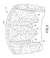
- FIG. 2 shows a magnified view of a rotor made in accordance with the current disclosure.
- FIG. 3 shows a magnified view of a drive link made in accordance with the current disclosure.
- FIGS. 4A-4F show pictorial representations of a method of manufacturing a rotor and drive link in accordance with the current disclosure.
- a motor is shown and generally designated by the numeral 10 .
- the motor includes among other features a rotor assembly 12 having a rotor 14 and a drive link 16 having an engagement end 18 .
- the drive link 16 is normally attached to a shaft 20 which provides power to the drive link 16 .
- This general configuration of a motor is known in the art.
- one of the improvements of the current disclosure is the rotor 14 having an inner surface 22 with a plurality of internal projections 24 , which can also be described as teeth 24 .
- the rotor 14 has an initial fatigue life and more specifically the teeth 24 have an initial fatigue life wherein the initial fatigue life of the teeth 24 of the inner surface 22 of the rotor 14 have been increased by the induction of compressive stresses as indicated by depressions 26 in FIG. 2 .
- the manifestation of the compressive stresses by the depressions 26 in the teeth 24 improves the fatigue life of the teeth 24 of the inner surface 22 of the rotor 14 .
- the depressions 26 are preferably positioned along the entire width of the inner surface 22 of the rotor 14 . Additionally, the circumferential base section 28 of the inner surface 22 can also contain the depressions 26 thereby increasing the overall fatigue life of the inner surface 22 . Preferably both sides 30 and 32 of each tooth 24 have been introduced to the compressive stresses and exhibit the depressions 26 .
- the drive link 16 having an outer surface 34 substantially corresponding with the inner surface 22 of the rotor 14 .
- the outer surface 34 of the drive link 16 also includes initial fatigue life which has been increased by the induction of compressive stresses in the outer surface 34 as manifested by depressions 36 as best seen in FIG. 3 .
- the external projections 38 which can also be described as teeth 38 , of the engagement end 18 of the drive link 16 have been preferably subjected to compressive stresses along the full width of the engagement end 18 and on both sides 40 and 42 of each tooth 38 .
- the drive link 16 , and more specifically the engagement end 18 of the drive link 16 includes an exterior circumference 44 that substantially corresponds with the base section 28 of the rotor 14 . This exterior circumference 44 is also preferably subjected to the compressive stresses to increase the fatigue life thereof.
- FIGS. 4A-4F an exemplary method of producing an improved rotor and/or improved drive link is shown.
- the method includes providing a rotor 14 having an inner surface 22 with the teeth 24 .
- Spherical indenting elements 46 FIG. 4C ), which can also be described as shot 46 , are also provided.
- the method includes forceably pressing the shot 46 against the inner surface 22 of the rotor 14 to induce compressive stresses in the rotor 14 to improve the fatigue life of the rotor 14 .
- the inducement of these compressive stresses is best illustrated by the depressions 26 as previously discussed.
- the method preferably includes forceably pressing the entire width of the inner surface 22 of the rotor 14 with the shot 46 as well as both sides 30 and 32 of the each tooth 24 as well as the base section 28 between the individual teeth 24 with the shot 46 .
- the drive link 16 with its outer surface 34 substantially corresponding with the inner surface 22 of the rotor 14 , is used to forceably press the shot 46 into the inner surface 22 of the rotor 14 .
- the shot 46 can be pressed between the outer surface 34 and inner surface 22 such that both the outer surface 34 and inner surface 22 are compressively stressed, or prestressed, to increase fatigue life, durability, and wear characteristics of both the rotor 14 and drive link 16 .
- the method can include using a static load, or fixed load, to compressively stress, at individual locations, the inner surface 22 of a rotor 14 and the outer surface 34 of a drive link 16 in order to increase the wear characteristics, for example the fatigue life, of the rotor 14 and drive link 16 .
- This static load can be applied through the shot 46 that can create the depressions 26 and 36 in the rotor 14 and the drive link 16 , respectively.
- An assembly unit 50 is assembled to control the movement of the rotor 14 and drive link 16 . More specifically the assembly unit 50 can restrict and contain the rotor 14 , drive link 16 , and the shot 46 before, during, and after the application of the force used to impart the compressive stress in the parts 14 and 16 .
- the assembly unit 50 includes a bottom base 51 which can include a counter bore 54 on the center to allow various size rotors and drive links to be processed.
- a plunger 56 is placed into the counter bore 54 to establish a centering location for the rotor. This plunger 56 can include a plate 55 and stem 57 as shown.
- the rotor is inserted such that the stem 57 passes through the opening 13 of the rotor 14 .
- the shot 46 which can also be described as balls 46 , is inserted into the opening 13 of the rotor 14 .
- this shot 46 has a diameter in the range of approximately 0.5 millimeters to 4.0 millimeters.
- the shot 46 can be mixed, stirred, or otherwise shifted or moved to facilitate that the inner surface, or at least the bottom portion of the inner surface, is substantially covered with the shot 46 .
- a plunger rod 58 is inserted onto the stem 57 of the plunger 56 and turned such that the splines 60 of the plunger rod 58 engage with the teeth 24 , which can also be described as rotor splines 24 , of the rotor 14 .
- the plunger rod 58 is replaced with a drive link 16 having an engagement end 18 which corresponds to the rotor 14 .
- a retaining cap 62 is placed over the base 51 , which can also be described as housing 51 , and secured into place with fasteners, such as bolts. If needed a plunger alignment sleeve (not shown) can be positioned around a plunger rod to ensure proper force transfer.
- the assembly unit 50 is positioned in the bay of a press 64 .
- Retaining cap spacers 66 can be applied around a plunger rod 58 to hold the retaining cap in position and to keep the cap 62 from separating from the housing 51 .
- the press 64 is then brought down and brought into contact with first the retaining cap spacer 66 and then the plunger rod 58 .
- the hammer 68 of the press 64 engages the plunger rod 58 and continues pressing until a desired force is reached.
- this desired force is 25 tons, but can vary according to application and the type of metal of which the rotor 14 and/or drive link 16 are comprised.
- this force is held for a desired period of time and then released. This length of time is preferably approximately 5 seconds but can vary as desired.
- the force is then reapplied for another time period to ensure the application of proper compressive stresses into the parts.
- this application of force in the assembly unit imparts the preferred compressive stresses in the bottom section of the rotor.
- the assembly unit 50 can then be disassembled, the rotor flipped, and the process repeated until the other half of the rotor has been processed.
- this force is applied throughout the full rotor in a single application.
- Some metal items made in accordance with the current disclosure went through more than 1,000,000 test cycles before developing a failure point, or a chip on one of its teeth. The applicants are unaware of any prior art metal rotors that achieve these levels.
- the test data measuring the level of residual compressive stress in a metal part, or rotor showed marked improvement in comparison to conventional metal rotors.
- the level of residual compressive stress in a rotor made in accordance with the current disclosure measured 50,000 psi.
- the level of residual compressive stress in conventional rotors that had not been subject to the current disclosure measured 0 psi. In increased levels of compressive stress are believed to directly equate to longer life of the part.
- test data indicates that rotors and drive links made in accordance with the current disclosure could increase this level to 150,000 psi. Additionally, parts made in accordance with the current disclosure possessed a recognizably more uniform residual compressive stress distribution than conventional parts, which can reduce the likely of weak spots in the rotor.
Landscapes
- Engineering & Computer Science (AREA)
- Mechanical Engineering (AREA)
- General Engineering & Computer Science (AREA)
- Rotary Pumps (AREA)
Abstract
Description
- This application is a Non-Provisional Utility application which claims benefit of co-pending U.S. Provisional Patent Application Ser. No. 60/733,221 filed Nov. 3, 2005, entitled “METHOD FOR IMPARTING RESIDUAL COMPRESSIVE STRESS IN METAL PARTS” which is hereby incorporated by reference.
- The present invention relates generally to increasing the wear characteristics of metal. More specifically, this invention relates to increasing the fatigue life, or hardening the metal, by imparting compressive stresses, such as residual compressive stresses, in the metal.
- It is known in the art to use small spherical items, such as shot or balls, to change various characteristics in the properties of a work piece. In most examples this shot is sent, or fired through the air, by a machine that imparts kinetic energy into the shot and directs the shot at the work piece. The shot then impacts against the work piece. This process is typically known as shot peening.
- Various attempts in the art have been made in order to try and improve this shot peening process. For example, U.S. Pat. No. 4,689,921 discloses improving a ceramic turbine rotor by rotating the rotor in abrasive grindstones to round the edges of the rotor.
- U.S. Pat. No. 5,125,191 discloses putting a work piece into a closed chamber and moving the work piece or chamber in an abrasive medium located in the chamber to adjust the characteristics of the work piece. This patent discusses by using the abrasive nature of the medium to generally smooth the work piece. This patent hones or abrades machine parts but does not impart any compressive stress on the work piece or affect the overall fatigue life of the work piece.
- U.S. Pat. No. 6,490,899 and U.S. Patent Application Publication 2003/0115922 generally disclose the use of ultrasonic energy to peen the blades of a rotor. These disclosures are generally focused on the external surfaces of those blades.
- U.S. Pat. No. 4,974,434 discloses a controlled shot peen method and a device for bending or leveling a work piece by shot peening. This patent fails to recognize the benefits of imparting compressive stresses in a work piece or the capability of increasing the fatigue life of internal components of a work piece.
- U.S. Pat. No. 6,009,980 discloses a ductal iron vehicle hub and a method for producing the same. This patent uses the conventional method of “shooting” the shot at the work piece and does not teach, and fails to realize the benefit of, adding compressive stresses to the internal components of a work piece.
- The advantage of having the capability of improving the fatigue life on the internal components of a metal part can be very beneficial in the application of rotors as used in engines or motors. The rotor typically has numerous teeth that project inwardly towards the axis. These teeth are used to transmit the torque and power from one portion of the motor to the next, typically from the shaft to the drive output. At any given moment only one internal tooth of the rotor could be engaged with the drive link. As such, a large amount of stress can be applied to any one individual tooth numerous times during the operation of the motor. It therefore becomes beneficial to increase the useful life, durability, and fatigue resistance of the individual internal teeth on a rotor.
- What is needed then is a rotor having internal components that have been processed to increase the wear characteristics thereof and a method of producing such a rotor. Preferably this rotor has been processed by the application of compressive stresses to the individual teeth of a rotor while the method is cost effective, consistent, and reliable. Preferably the method could produce a drive link that has improved wear characteristics such that the drive link and rotor, two parts of a motor that typically experience the greatest levels of stress, can be improved such that the overall useful life and potential efficiency of the motor is increased. This needed rotor, drive link, and method of producing the same is lacking in the art.
- Disclosed herein is a method of hardening metal parts, such as a rotor or drive link, and parts thus produced. Preferably the method includes imparting residual compressive stresses into the metal parts and uses various small ball type structures to create small compressions in the surfaces of the metal parts. The compressions apply residual stresses to the parts, which strengthen the metal. The substantial uniform ball type structures are pressed into the metal part to control the application of stress into the part and maintain substantial uniform properties within the metal part, which resists future stresses as the part is used in its desired machinery and/or processes.
- Also disclosed is a method for producing a rotor. The method includes providing substantially spherical indenting elements and a metal rotor having an inner surface. The inner surface of the rotor includes a plurality of internal projections. The method includes forceably pressing the indenting elements against the inner surface of the rotor to induce compressive stresses in the inner surface to improve the fatigue life of the rotor.
- Preferably the method further includes forceably compressing the entire width of the inner surface of the rotor to induce the compressive stresses therein. Each internal projection can include a first and a second side wherein the indenting elements are forceably pressed against both sides of each internal projection to induce the compressive stresses. The inner surface of the rotor can further include a circumferential base section extending between each internal projection wherein the indenting elements are pressed against the base section. The indenting elements are preferably substantially spherical and can have a diameter in the range of approximately 0.5 millimeters to approximately 0.4 millimeters.
- In an alternate embodiment the method further includes using a drive link having an outer surface substantially corresponding with the inner surface of the rotor to press the indenting elements against the inner surface of the rotor to induce the compressive stresses in the rotor. The use of a drive link can induce compressive stresses in the outer surface of the drive link thereby improving the fatigue life of the drive link through the forceably pressing the indenting elements between the outer surface of the drive link and the inner surface of the rotor. The drive link can include an exterior circumference substantially mirroring the base sections of the rotor such that the indenting elements can be forceably pressed against the exterior circumference of the drive link.
- Also disclosed is an improved metal rotor having an inner surface with a plurality of internal projections wherein each internal projection has an initial fatigue life. The fatigue life of the internal projections of the inner surface of the rotor have been increased by inducing compressive stresses in the internal projections to improve the overall fatigue life of the internal projections and the overall fatigue life of the rotor. The internal projections of the inner surface of the rotor have been preferably compressed under a static load by spherical indenting elements.
- Also enclosed is an improved rotor and drive link combination wherein the rotor and drive link have been formed by subjecting the inner surface of the rotor and the outer surface of the drive link to compressive stresses to increase the fatigue life of the rotor and the drive link.
- It is therefore a general object of the present invention to provide an improved rotor.
- Another object of the present invention is to provide an improved drive link.
- Another object of the present invention is to provide an improved rotor and drive link combination.
- Still another object of the present invention is to provide an improved method for producing an improved rotor and/or drive link.
- Still another object of the present invention is to provide a method for subjecting internal surfaces of a rotor to compressive stresses to increase the fatigue life thereof.
- Another object of the present invention is to provide a method that concurrently subjects the internal surface of a rotor and the external surface of a corresponding drive link to compressive stresses to improve fatigue life of both parts.
- Other and further objects, features and advantages of the present invention will be readily apparent to those skilled in the art upon reading of the following disclosure when taken in conjunction with the accompanying drawings.
-
FIG. 1A is an exploded assembly view of a motor including an example of a drive link and rotor assembly having a rotor. -
FIG. 1B is an end view of the engaging portion of a drive link with a rotor. -
FIG. 2 shows a magnified view of a rotor made in accordance with the current disclosure. -
FIG. 3 shows a magnified view of a drive link made in accordance with the current disclosure. -
FIGS. 4A-4F show pictorial representations of a method of manufacturing a rotor and drive link in accordance with the current disclosure. - Looking generally at
FIG. 1A a motor is shown and generally designated by the numeral 10. The motor includes among other features arotor assembly 12 having arotor 14 and adrive link 16 having anengagement end 18. Thedrive link 16 is normally attached to ashaft 20 which provides power to thedrive link 16. This general configuration of a motor is known in the art. - However, one of the improvements of the current disclosure is the
rotor 14 having aninner surface 22 with a plurality ofinternal projections 24, which can also be described asteeth 24. Therotor 14 has an initial fatigue life and more specifically theteeth 24 have an initial fatigue life wherein the initial fatigue life of theteeth 24 of theinner surface 22 of therotor 14 have been increased by the induction of compressive stresses as indicated bydepressions 26 inFIG. 2 . The manifestation of the compressive stresses by thedepressions 26 in theteeth 24 improves the fatigue life of theteeth 24 of theinner surface 22 of therotor 14. - As best illustrated in
FIG. 2 , thedepressions 26 are preferably positioned along the entire width of theinner surface 22 of therotor 14. Additionally, thecircumferential base section 28 of theinner surface 22 can also contain thedepressions 26 thereby increasing the overall fatigue life of theinner surface 22. Preferably bothsides tooth 24 have been introduced to the compressive stresses and exhibit thedepressions 26. - Also included is the
drive link 16 having anouter surface 34 substantially corresponding with theinner surface 22 of therotor 14. Theouter surface 34 of thedrive link 16 also includes initial fatigue life which has been increased by the induction of compressive stresses in theouter surface 34 as manifested bydepressions 36 as best seen inFIG. 3 . Theexternal projections 38, which can also be described asteeth 38, of theengagement end 18 of thedrive link 16 have been preferably subjected to compressive stresses along the full width of theengagement end 18 and on bothsides tooth 38. Thedrive link 16, and more specifically theengagement end 18 of thedrive link 16 includes anexterior circumference 44 that substantially corresponds with thebase section 28 of therotor 14. Thisexterior circumference 44 is also preferably subjected to the compressive stresses to increase the fatigue life thereof. - Now referring generally to
FIGS. 4A-4F , an exemplary method of producing an improved rotor and/or improved drive link is shown. The method includes providing arotor 14 having aninner surface 22 with theteeth 24. Spherical indenting elements 46 (FIG. 4C ), which can also be described asshot 46, are also provided. The method includes forceably pressing theshot 46 against theinner surface 22 of therotor 14 to induce compressive stresses in therotor 14 to improve the fatigue life of therotor 14. The inducement of these compressive stresses is best illustrated by thedepressions 26 as previously discussed. - The method preferably includes forceably pressing the entire width of the
inner surface 22 of therotor 14 with theshot 46 as well as bothsides tooth 24 as well as thebase section 28 between theindividual teeth 24 with theshot 46. - In a preferred embodiment the
drive link 16, with itsouter surface 34 substantially corresponding with theinner surface 22 of therotor 14, is used to forceably press theshot 46 into theinner surface 22 of therotor 14. Additionally, theshot 46 can be pressed between theouter surface 34 andinner surface 22 such that both theouter surface 34 andinner surface 22 are compressively stressed, or prestressed, to increase fatigue life, durability, and wear characteristics of both therotor 14 and drivelink 16. - Alternately described, the method can include using a static load, or fixed load, to compressively stress, at individual locations, the
inner surface 22 of arotor 14 and theouter surface 34 of adrive link 16 in order to increase the wear characteristics, for example the fatigue life, of therotor 14 and drivelink 16. This static load can be applied through theshot 46 that can create thedepressions rotor 14 and thedrive link 16, respectively. - Referring back to
FIGS. 4A-4F , an exemplary method of producing the rotor and/or drive link can be described as follows. Anassembly unit 50 is assembled to control the movement of therotor 14 and drivelink 16. More specifically theassembly unit 50 can restrict and contain therotor 14,drive link 16, and theshot 46 before, during, and after the application of the force used to impart the compressive stress in theparts assembly unit 50 includes abottom base 51 which can include a counter bore 54 on the center to allow various size rotors and drive links to be processed. Aplunger 56 is placed into the counter bore 54 to establish a centering location for the rotor. Thisplunger 56 can include aplate 55 and stem 57 as shown. - Next the rotor is inserted such that the
stem 57 passes through theopening 13 of therotor 14. Theshot 46, which can also be described asballs 46, is inserted into theopening 13 of therotor 14. Preferably this shot 46 has a diameter in the range of approximately 0.5 millimeters to 4.0 millimeters. Next theshot 46 can be mixed, stirred, or otherwise shifted or moved to facilitate that the inner surface, or at least the bottom portion of the inner surface, is substantially covered with theshot 46. - Next a
plunger rod 58 is inserted onto thestem 57 of theplunger 56 and turned such that thesplines 60 of theplunger rod 58 engage with theteeth 24, which can also be described as rotor splines 24, of therotor 14. In a preferred embodiment theplunger rod 58 is replaced with adrive link 16 having anengagement end 18 which corresponds to therotor 14. A retainingcap 62 is placed over thebase 51, which can also be described ashousing 51, and secured into place with fasteners, such as bolts. If needed a plunger alignment sleeve (not shown) can be positioned around a plunger rod to ensure proper force transfer. - Next the
assembly unit 50 is positioned in the bay of apress 64. Retaining cap spacers 66 can be applied around aplunger rod 58 to hold the retaining cap in position and to keep thecap 62 from separating from thehousing 51. Thepress 64 is then brought down and brought into contact with first the retaining cap spacer 66 and then theplunger rod 58. Thehammer 68 of thepress 64 engages theplunger rod 58 and continues pressing until a desired force is reached. Preferably this desired force is 25 tons, but can vary according to application and the type of metal of which therotor 14 and/or drivelink 16 are comprised. Preferably this force is held for a desired period of time and then released. This length of time is preferably approximately 5 seconds but can vary as desired. Preferably the force is then reapplied for another time period to ensure the application of proper compressive stresses into the parts. - In one embodiment this application of force in the assembly unit imparts the preferred compressive stresses in the bottom section of the rotor. The
assembly unit 50 can then be disassembled, the rotor flipped, and the process repeated until the other half of the rotor has been processed. In an alternate embodiment this force is applied throughout the full rotor in a single application. - Various tests have been performed on rotors made in accordance with the current disclosure. These tests determined that after more than 806,000 motor revolutions there was an absence of noticeable and/or discernible chipping, nicks, pitting, or cracks in the teeth of the rotors. This is typically unprecedented in the metal parts industry and can be explained by the theory that the compressive stresses have created depressions and resist the effects of imposed bending stresses from external loads during the operation of the motors. As such these surfaces treated are much harder and fatigue resistance is greatly improved.
- Some metal items made in accordance with the current disclosure went through more than 1,000,000 test cycles before developing a failure point, or a chip on one of its teeth. The applicants are unaware of any prior art metal rotors that achieve these levels. The test data measuring the level of residual compressive stress in a metal part, or rotor, showed marked improvement in comparison to conventional metal rotors. For example, the level of residual compressive stress in a rotor made in accordance with the current disclosure measured 50,000 psi. The level of residual compressive stress in conventional rotors that had not been subject to the current disclosure measured 0 psi. In increased levels of compressive stress are believed to directly equate to longer life of the part. The test data indicates that rotors and drive links made in accordance with the current disclosure could increase this level to 150,000 psi. Additionally, parts made in accordance with the current disclosure possessed a recognizably more uniform residual compressive stress distribution than conventional parts, which can reduce the likely of weak spots in the rotor.
- Additional benefits received from the exposure of the parts to the compressive stresses and the subsequent depressions formed in the parts therein could also lead to improved rotor and/or drive link performance. For example, these depressions are believed to provide locations where islands of contained fluid, such as oil or lubricant, were stored during operation of the motors. This in essence provides a self-lubricating surface that can reduce friction in the operation of the rotors, drive links and motors. This can further facilitate a longer fatigue life and reduced wear on the parts.
- Thus, although there have been described particular embodiments of the present invention of a new and useful METHOD FOR IMPARTING RESIDUAL COMPRESSIVE STRESS IN METAL PARTS, it is not intended that such references be construed as limitations upon the scope of this invention except as set forth in the following claims.
Claims (17)
Priority Applications (1)
| Application Number | Priority Date | Filing Date | Title |
|---|---|---|---|
| US11/556,679 US20070140887A1 (en) | 2005-11-03 | 2006-11-03 | Method for Imparting Residual Compressive Stress in Metal Parts |
Applications Claiming Priority (2)
| Application Number | Priority Date | Filing Date | Title |
|---|---|---|---|
| US73322105P | 2005-11-03 | 2005-11-03 | |
| US11/556,679 US20070140887A1 (en) | 2005-11-03 | 2006-11-03 | Method for Imparting Residual Compressive Stress in Metal Parts |
Publications (1)
| Publication Number | Publication Date |
|---|---|
| US20070140887A1 true US20070140887A1 (en) | 2007-06-21 |
Family
ID=38173719
Family Applications (1)
| Application Number | Title | Priority Date | Filing Date |
|---|---|---|---|
| US11/556,679 Abandoned US20070140887A1 (en) | 2005-11-03 | 2006-11-03 | Method for Imparting Residual Compressive Stress in Metal Parts |
Country Status (1)
| Country | Link |
|---|---|
| US (1) | US20070140887A1 (en) |
Cited By (1)
| Publication number | Priority date | Publication date | Assignee | Title |
|---|---|---|---|---|
| US20110194950A1 (en) * | 2010-02-10 | 2011-08-11 | Shenoi Ramesh B | Efficiency improvements for liquid ring pumps |
Citations (6)
| Publication number | Priority date | Publication date | Assignee | Title |
|---|---|---|---|---|
| US4689921A (en) * | 1984-11-13 | 1987-09-01 | Ngk Spark Plug Co., Ltd. | Process of contouring the edges of a ceramic rotor |
| US4974434A (en) * | 1988-07-13 | 1990-12-04 | Dornier Gmbh | Controlled shot peening |
| US5125191A (en) * | 1982-09-08 | 1992-06-30 | Extrude Hone Corporation | Abrasive flow machining with an in situ viscous plastic medium |
| US6009980A (en) * | 1996-04-16 | 2000-01-04 | Meritor Automotive, Inc. | Ductile iron vehicle hub and method for producing same |
| US6490899B2 (en) * | 2000-11-16 | 2002-12-10 | Snecma Moteurs | Method and apparatus for peening tops of cooled blades |
| US20030115922A1 (en) * | 2000-09-21 | 2003-06-26 | Berthelet Benoit Jean Henri | Transverse utrasound peening of blades on a rotor |
-
2006
- 2006-11-03 US US11/556,679 patent/US20070140887A1/en not_active Abandoned
Patent Citations (7)
| Publication number | Priority date | Publication date | Assignee | Title |
|---|---|---|---|---|
| US5125191A (en) * | 1982-09-08 | 1992-06-30 | Extrude Hone Corporation | Abrasive flow machining with an in situ viscous plastic medium |
| US4689921A (en) * | 1984-11-13 | 1987-09-01 | Ngk Spark Plug Co., Ltd. | Process of contouring the edges of a ceramic rotor |
| US4974434A (en) * | 1988-07-13 | 1990-12-04 | Dornier Gmbh | Controlled shot peening |
| US6009980A (en) * | 1996-04-16 | 2000-01-04 | Meritor Automotive, Inc. | Ductile iron vehicle hub and method for producing same |
| US20030115922A1 (en) * | 2000-09-21 | 2003-06-26 | Berthelet Benoit Jean Henri | Transverse utrasound peening of blades on a rotor |
| US6837085B2 (en) * | 2000-09-21 | 2005-01-04 | Snecma Moteurs | Transverse ultrasound peening of blades on a rotor |
| US6490899B2 (en) * | 2000-11-16 | 2002-12-10 | Snecma Moteurs | Method and apparatus for peening tops of cooled blades |
Cited By (2)
| Publication number | Priority date | Publication date | Assignee | Title |
|---|---|---|---|---|
| US20110194950A1 (en) * | 2010-02-10 | 2011-08-11 | Shenoi Ramesh B | Efficiency improvements for liquid ring pumps |
| WO2011100346A3 (en) * | 2010-02-10 | 2012-08-02 | Gardner Denver Nash Llc | Liquid ring pump provided with textured surfaces |
Similar Documents
| Publication | Publication Date | Title |
|---|---|---|
| US20070169532A1 (en) | Method and apparatus for increasing the fatigue life, in particular the bending fatigue life and the torsional fatigue life of crankshafts | |
| KR20050004843A (en) | Method of producing bearing raceway member | |
| JP5602011B2 (en) | Crank drive | |
| JP2973666B2 (en) | Belt-type continuously variable transmission for vehicles | |
| JP2002137179A (en) | Electric tool | |
| US20070140887A1 (en) | Method for Imparting Residual Compressive Stress in Metal Parts | |
| JPH10231908A (en) | Rolling element for toroidal type continuously variable transmission and method of manufacturing the same | |
| JP5271698B2 (en) | How to correct the eccentric shaft | |
| JP5994377B2 (en) | Radial rolling bearing inner ring and manufacturing method thereof | |
| JP2016205514A (en) | Silent chain, bush chain and roller chain | |
| Leghorn | The story of shot peening | |
| JP2010112249A (en) | Hermetic compressor | |
| JP3936447B2 (en) | Manufacturing method of swash plate type compressor shoe | |
| US6780139B2 (en) | Toroidal continuously variable transmission | |
| JP2003329048A (en) | Manufacturing method for bearing raceway member | |
| CN101850530A (en) | Fretting Wear Gear Mirror Polishing System | |
| US6176806B1 (en) | Cam disk for toroidal type continuously variable transmission | |
| JP2024084092A (en) | Drive mechanism | |
| US20040231622A1 (en) | Valve train for internal combustion engine | |
| US20040244529A1 (en) | Workpiece, in particular a crankshaft | |
| US1632255A (en) | Rotary percussion implement | |
| JPS58150083A (en) | Opposed swash plate system compressor | |
| JPH05288257A (en) | Rolling sliding component | |
| CN114270060A (en) | Material treatment for diamond to diamond reactive material bearing bonding | |
| JP2020029609A (en) | Treatment method for improving fretting fatigue strength |
Legal Events
| Date | Code | Title | Description |
|---|---|---|---|
| AS | Assignment |
Owner name: WHITE DRIVE PRODUCTS, INC., KENTUCKY Free format text: ASSIGNMENT OF ASSIGNORS INTEREST;ASSIGNOR:PERKINS, GERARD T.;REEL/FRAME:018977/0473 Effective date: 20070227 |
|
| AS | Assignment |
Owner name: US BANK, NA, KENTUCKY Free format text: SECURITY AGREEMENT;ASSIGNOR:WHITE DRIVE PRODUCTS, INC.;REEL/FRAME:022619/0047 Effective date: 20090429 Owner name: US BANK, NA,KENTUCKY Free format text: SECURITY AGREEMENT;ASSIGNOR:WHITE DRIVE PRODUCTS, INC.;REEL/FRAME:022619/0047 Effective date: 20090429 |
|
| STCB | Information on status: application discontinuation |
Free format text: ABANDONED -- FAILURE TO PAY ISSUE FEE |
|
| STCB | Information on status: application discontinuation |
Free format text: ABANDONED -- FAILURE TO PAY ISSUE FEE |
|
| AS | Assignment |
Owner name: WHITE DRIVE PRODUCTS, INC., KENTUCKY Free format text: RELEASE BY SECURED PARTY;ASSIGNOR:US BANK;REEL/FRAME:040353/0170 Effective date: 20160908 |