US20050128362A1 - Multipath video reception system - Google Patents
Multipath video reception system Download PDFInfo
- Publication number
- US20050128362A1 US20050128362A1 US11/001,633 US163304A US2005128362A1 US 20050128362 A1 US20050128362 A1 US 20050128362A1 US 163304 A US163304 A US 163304A US 2005128362 A1 US2005128362 A1 US 2005128362A1
- Authority
- US
- United States
- Prior art keywords
- analog
- digital
- demodulated
- video signal
- signal
- Prior art date
- Legal status (The legal status is an assumption and is not a legal conclusion. Google has not performed a legal analysis and makes no representation as to the accuracy of the status listed.)
- Granted
Links
Images


Classifications
-
- H—ELECTRICITY
- H04—ELECTRIC COMMUNICATION TECHNIQUE
- H04N—PICTORIAL COMMUNICATION, e.g. TELEVISION
- H04N5/00—Details of television systems
- H04N5/44—Receiver circuitry for the reception of television signals according to analogue transmission standards
-
- H—ELECTRICITY
- H04—ELECTRIC COMMUNICATION TECHNIQUE
- H04N—PICTORIAL COMMUNICATION, e.g. TELEVISION
- H04N5/00—Details of television systems
- H04N5/44—Receiver circuitry for the reception of television signals according to analogue transmission standards
- H04N5/46—Receiver circuitry for the reception of television signals according to analogue transmission standards for receiving on more than one standard at will
-
- H—ELECTRICITY
- H04—ELECTRIC COMMUNICATION TECHNIQUE
- H04B—TRANSMISSION
- H04B7/00—Radio transmission systems, i.e. using radiation field
- H04B7/02—Diversity systems; Multi-antenna system, i.e. transmission or reception using multiple antennas
- H04B7/04—Diversity systems; Multi-antenna system, i.e. transmission or reception using multiple antennas using two or more spaced independent antennas
- H04B7/08—Diversity systems; Multi-antenna system, i.e. transmission or reception using multiple antennas using two or more spaced independent antennas at the receiving station
- H04B7/0837—Diversity systems; Multi-antenna system, i.e. transmission or reception using multiple antennas using two or more spaced independent antennas at the receiving station using pre-detection combining
- H04B7/0842—Weighted combining
-
- H—ELECTRICITY
- H04—ELECTRIC COMMUNICATION TECHNIQUE
- H04L—TRANSMISSION OF DIGITAL INFORMATION, e.g. TELEGRAPHIC COMMUNICATION
- H04L1/00—Arrangements for detecting or preventing errors in the information received
- H04L1/02—Arrangements for detecting or preventing errors in the information received by diversity reception
- H04L1/06—Arrangements for detecting or preventing errors in the information received by diversity reception using space diversity
-
- H—ELECTRICITY
- H04—ELECTRIC COMMUNICATION TECHNIQUE
- H04N—PICTORIAL COMMUNICATION, e.g. TELEVISION
- H04N21/00—Selective content distribution, e.g. interactive television or video on demand [VOD]
- H04N21/40—Client devices specifically adapted for the reception of or interaction with content, e.g. set-top-box [STB]; Operations thereof
- H04N21/41—Structure of client; Structure of client peripherals
- H04N21/426—Internal components of the client ; Characteristics thereof
- H04N21/42607—Internal components of the client ; Characteristics thereof for processing the incoming bitstream
- H04N21/4263—Internal components of the client ; Characteristics thereof for processing the incoming bitstream involving specific tuning arrangements, e.g. two tuners
- H04N21/42638—Internal components of the client ; Characteristics thereof for processing the incoming bitstream involving specific tuning arrangements, e.g. two tuners involving a hybrid front-end, e.g. analog and digital tuners
-
- H—ELECTRICITY
- H04—ELECTRIC COMMUNICATION TECHNIQUE
- H04N—PICTORIAL COMMUNICATION, e.g. TELEVISION
- H04N21/00—Selective content distribution, e.g. interactive television or video on demand [VOD]
- H04N21/40—Client devices specifically adapted for the reception of or interaction with content, e.g. set-top-box [STB]; Operations thereof
- H04N21/43—Processing of content or additional data, e.g. demultiplexing additional data from a digital video stream; Elementary client operations, e.g. monitoring of home network or synchronising decoder's clock; Client middleware
- H04N21/442—Monitoring of processes or resources, e.g. detecting the failure of a recording device, monitoring the downstream bandwidth, the number of times a movie has been viewed, the storage space available from the internal hard disk
- H04N21/44209—Monitoring of downstream path of the transmission network originating from a server, e.g. bandwidth variations of a wireless network
-
- H—ELECTRICITY
- H04—ELECTRIC COMMUNICATION TECHNIQUE
- H04N—PICTORIAL COMMUNICATION, e.g. TELEVISION
- H04N21/00—Selective content distribution, e.g. interactive television or video on demand [VOD]
- H04N21/60—Network structure or processes for video distribution between server and client or between remote clients; Control signalling between clients, server and network components; Transmission of management data between server and client, e.g. sending from server to client commands for recording incoming content stream; Communication details between server and client
- H04N21/63—Control signaling related to video distribution between client, server and network components; Network processes for video distribution between server and clients or between remote clients, e.g. transmitting basic layer and enhancement layers over different transmission paths, setting up a peer-to-peer communication via Internet between remote STB's; Communication protocols; Addressing
- H04N21/631—Multimode Transmission, e.g. transmitting basic layers and enhancement layers of the content over different transmission paths or transmitting with different error corrections, different keys or with different transmission protocols
-
- H—ELECTRICITY
- H04—ELECTRIC COMMUNICATION TECHNIQUE
- H04B—TRANSMISSION
- H04B7/00—Radio transmission systems, i.e. using radiation field
- H04B7/02—Diversity systems; Multi-antenna system, i.e. transmission or reception using multiple antennas
- H04B7/04—Diversity systems; Multi-antenna system, i.e. transmission or reception using multiple antennas using two or more spaced independent antennas
- H04B7/08—Diversity systems; Multi-antenna system, i.e. transmission or reception using multiple antennas using two or more spaced independent antennas at the receiving station
- H04B7/0802—Diversity systems; Multi-antenna system, i.e. transmission or reception using multiple antennas using two or more spaced independent antennas at the receiving station using antenna selection
- H04B7/0817—Diversity systems; Multi-antenna system, i.e. transmission or reception using multiple antennas using two or more spaced independent antennas at the receiving station using antenna selection with multiple receivers and antenna path selection
-
- H—ELECTRICITY
- H04—ELECTRIC COMMUNICATION TECHNIQUE
- H04B—TRANSMISSION
- H04B7/00—Radio transmission systems, i.e. using radiation field
- H04B7/02—Diversity systems; Multi-antenna system, i.e. transmission or reception using multiple antennas
- H04B7/04—Diversity systems; Multi-antenna system, i.e. transmission or reception using multiple antennas using two or more spaced independent antennas
- H04B7/08—Diversity systems; Multi-antenna system, i.e. transmission or reception using multiple antennas using two or more spaced independent antennas at the receiving station
- H04B7/0882—Diversity systems; Multi-antenna system, i.e. transmission or reception using multiple antennas using two or more spaced independent antennas at the receiving station using post-detection diversity
- H04B7/0885—Diversity systems; Multi-antenna system, i.e. transmission or reception using multiple antennas using two or more spaced independent antennas at the receiving station using post-detection diversity with combination
-
- H—ELECTRICITY
- H04—ELECTRIC COMMUNICATION TECHNIQUE
- H04L—TRANSMISSION OF DIGITAL INFORMATION, e.g. TELEGRAPHIC COMMUNICATION
- H04L1/00—Arrangements for detecting or preventing errors in the information received
- H04L2001/0092—Error control systems characterised by the topology of the transmission link
- H04L2001/0096—Channel splitting in point-to-point links
-
- H—ELECTRICITY
- H04—ELECTRIC COMMUNICATION TECHNIQUE
- H04N—PICTORIAL COMMUNICATION, e.g. TELEVISION
- H04N21/00—Selective content distribution, e.g. interactive television or video on demand [VOD]
- H04N21/40—Client devices specifically adapted for the reception of or interaction with content, e.g. set-top-box [STB]; Operations thereof
- H04N21/43—Processing of content or additional data, e.g. demultiplexing additional data from a digital video stream; Elementary client operations, e.g. monitoring of home network or synchronising decoder's clock; Client middleware
- H04N21/431—Generation of visual interfaces for content selection or interaction; Content or additional data rendering
- H04N21/4318—Generation of visual interfaces for content selection or interaction; Content or additional data rendering by altering the content in the rendering process, e.g. blanking, blurring or masking an image region
Definitions
- the invention relates to a system for the multipath reception of video signals, such as television signals, which may include image and/or sound signals.
- Multipath reception includes the reception of electromagnetic (“EM”) signals on one of several transmission paths or channels.
- Multipath reception of EM signals including broadcast signals, may be accomplished using antenna diversity, and/or frequency diversity.
- Antenia diversity includes the use of one or more antennas.
- Frequency diversity includes reception on one of several receiver frequencies.
- An antenna diversity receiver system is an EM receiving system that includes an EM receiver, which may be connected to one of several antennas.
- the antennas may be spatially separated.
- the EM receiver may include a telephone system, and/or a broadcast receiver, such as a television receiver or a telephone system.
- the EM receiver may include a selector switch that connects one of the antennas to the EM receiver on the basis of specified criteria, such as reception field strength and the interference, to receive the signal at an acceptable level of quality.
- This type of antenna diversity receiver system may be used in vehicles to receive broadcast signals, such as television signals.
- an antenna diversity receiver system may include window antennas integrated into the windows of the vehicle.
- a frequency diversity receiver system is an EM receiving system that may include at least two radio receivers.
- One radio receiver may be an operating receiver, while the other radio receiver may be a search and test receiver that searches for alternative reception frequencies and tests the reception quality at those frequencies. If the search receiver finds an alternative reception frequency that provides a better reception quality than the current reception frequency, either the operating receiver is tuned to the alternate reception frequency or the search and operating receivers exchange roles. If the search and operating receivers exchange roles, the search receiver stays tuned to the alternate reception frequency and assumes the role of the operating receiver. The operating receiver assumes the role of the search receiver and thus searches for alternative reception frequencies and tests the reception quality at those frequencies.
- Frequency diversity receiver systems are suitable for use in vehicles because as the vehicle moves, the reception conditions may change as result of the changing surroundings.
- Antenna and frequency diversity may be used in combination, for example, in a combined diversity reception system.
- a combined diversity reception system may include several antennas and receivers.
- the combined diversity reception system may also include a selector switch that may place the antennas in communication with the receivers in any combination.
- Digital receiver systems used for receiving digital broadcast signals, are becoming more widely used because an increasing number of radio and television programs are being broadcast digitally, for example using “Digital Video Broadcasting—Terrestrial” or “DVB-T.”
- Digital broadcast signals such as video and television
- digital video signals require special digital receiver systems for reception, and may not be implemented in all locations. Therefore, there is a need for reception systems that process both analog and digital broadcast signals, such as analog and digital video signals. This need is particularly acute for mobile receivers, such as those used in vehicles,
- This multipath video reception system includes at least two receivers and may include at least one antenna. At least one of the receivers receives and processes analog video signals and at least one of the receivers receives and processes digital video signals. Each receiver may include an automatic gain control for regulating the level of the received video. signal. Each receiver may also include an analog demodulator and a digital demodulator for demodulating analog and digital video signals, respectively.
- the system may also include an antenna selector network that places the receivers in communication with the antenna or antennas.
- the system may include an analog selector unit that selects the demodulated analog video signal with the highest reception quality.
- the system may include a digital selector unit that selects the demodulated digital video signal with the highest reception quality.
- the digital selector unit may include a second diversity unit, one or more demultiplexers, a third diversity unit and a decoder. If the digital demodulators provide a package-oriented MPEG multi-program transport stream (“MPTS”), the digital selector unit may include an MPTS diversity unit, and an MPEG decoder. The MPTS diversity unit may select the MPEG multi-program transport stream having fewer faulty packages, and forward the selected MPEG multi-program transport stream to the MPEG decoder.
- MPTS package-oriented MPEG multi-program transport stream
- each of the output signals from the MPTS diversity unit may be demultiplexed by one or more demultiplexers into single program (transport) streams (“SPTS”).
- SPTS single program
- the output signals of the one or more demultiplexers may be communicated to an SPTS, PES or ES diversity unit which selects the data stream with the best quality from SPTS, package-oriented elementary streams (“PES”) or pure elementary streams (“ES”).
- PES package-oriented elementary streams
- ES pure elementary streams
- the digital demodulators may provide a package-oriented MPEG multi-program transport stream, abbreviated to MPTS, to an MPTS diversity unit, which selects an MPEG multi-program transport stream with fault-free packages and forwards it to an MPEG decoder.
- MPTS package-oriented MPEG multi-program transport stream
- MPTS diversity unit which selects an MPEG multi-program transport stream with fault-free packages and forwards it to an MPEG decoder.
- the demodulated analog and digital video signals, or those selected by an analog selector unit and/or a digital selector unit may be communicated to a diversity unit.
- the diversity unit may digitize the analog video signal, synchronize the analog and digital video signals, and/or combine the received analog and digital image signals.
- the diversity unit may combine the analog and digital signals using a weighted addition to produce a video signal with quality at least as high as the qualitatively better of the analog and digital signals.
- the resultant video signal may equal the analog video signal, the digital video signal, or a combination of the analog and digital signals.
- the weighted addition of the two signals may be performed in the frequency or time domain.
- the low-frequency portion of the digital video signal may be combined with the high-frequency portion of the analog video signal, or vice versa.
- the combination or diversity may take place between a chrominance signal and a luminance signal.
- the system may include a control unit that controls the other components of the system, including the following in any combination: the antenna s elector network, the receivers, the analog selector unit, the digital selector unit, the diversity unit, and the output unit.
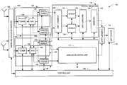
- FIG. 1 is a block diagram of a multipath video reception system.
- FIG. 2 is a diagram of transport stream packages received and produced by the second diversity unit of the system of FIG. 1 .
- FIG. 3 is a diagram of data packages received and produced by the third diversity unit of the system of FIG. 1 .
- FIG. 4 is a diagram of data packages received and produced by the first diversity unit of the system of FIG. 1 .
- FIG. 5 is a diagram of a weighted addition of two image signals, each including a luminance signal and a chrominance signal, on the basis of an 8 ⁇ 8 pixel.
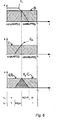
- FIG. 6 is a diagram of a weighted addition of two image signals in the frequency domain.
- a multipath video reception system is shown in FIG. 1 .
- the system 100 receives and processes electromagnetic (“EM”) signals, such as video signals.
- EM electromagnetic
- the system 100 may process the image part and the sound part of the video signal separately because the image signal contains vertically synchronous signals and horizontally synchronous signals.
- the system 100 may be used for mobile reception under difficult, frequently changing reception conditions, for example, in a vehicle.
- the system 100 is not limited to mobile use and may be used in a fixed environment, such as a home or office.
- the system 100 may include a first and a second analog receiver 104 , 108 , respectively, a digital selector unit 110 , an analog selector unit 112 , and a first diversity unit 114 .
- the system may also include a first antenna 122 , a second antenna 124 , and an antenna selector network 128 .
- the first and second antennas 122 , 124 respectively, may be attached to inputs of the antenna selector network 128 .
- the antenna selector network 128 may have any number of inputs and outputs.
- the antenna selector network 128 may include a number of inputs equal to the number of antennas.
- the number of outputs may equal the number of inputs.
- the antenna selector network 128 places the first and second antennas 122 , 124 , respectively, in communication with the first and second analog receivers 104 , 108 , respectively, and the first and second digital receivers 102 , 106 , respectively.
- the receivers 102 , 104 , 106 , and 106 may each include a tuner, an automatic gain control (“AGC”), and a demodulator.
- the first digital receiver 102 may include a first tuner 130 , a first AGC 132 , and a first digital demodulator 134 .
- the second digital receiver 106 may include a second tuner 140 , a second AGC 142 , and a second digital demodulator 146 .
- the first analog receiver 104 may include a first tuner 130 , a first AGC 132 , and a first analog demodulator 136 .
- the second analog receiver 108 may include a second tuner 140 , a second AGC 142 , and a second digital demodulator 146 .
- the first analog receiver 104 and the first digital receiver 102 may share a tuner 130 and/or an AGC 132 , or may each include a separate tuner and/or AGC.
- the second analog receiver 108 and the second digital receiver 106 may share a tuner 140 and/or an AGC 122 , or may each include a separate tuner and/or AGC.
- each tuner 130 and 140 may be in communication with the input of an AGC 132 and 142 , respectively.
- the output of each AGC 132 , 142 may be in communication with the input a digital demodulator and an analog demodulator.
- the output of AGC 132 may be in communication with a first digital demodulator 134 and a first analog demodulator 136 .
- the output of AGC 142 may be in communication with a second digital demodulator 144 and a second analog demodulator 146 .
- the outputs of the first and second digital demodulators 134 , 146 may be in communication with the inputs of a digital selector unit 110 .
- the digital selector unit 110 may include a second diversity unit 150 , first and second demultiplexers 152 , 154 , respectively, a third diversity unit 156 , and a decoder 156 .
- the second diversity unit 150 may include a multi-program transport stream (“MPTS”) diversity u nit f or single-program transport streams (“STPS”), package-oriented elementary streams (“PES”), or pure elementary streams (“ES”).
- MPTS multi-program transport stream
- STPS single-program transport streams
- PES package-oriented elementary streams
- ES pure elementary streams
- the first and second demultiplexers 152 , 154 respectively, may include an MPTS demultiplexer with a program filter.
- the outputs of the first and second demultiplexers 152 , 154 may be in communication with the inputs of the third diversity unit 156 .
- the diversity unit 156 may include an STPS, PES, or ES diversity unit that includes a delay balance module.
- the output of the third diversity unit 156 may be in communication with the input of the decoder 156 , which may include an MPEG decoder.
- the output of the decoder 156 may be in communication with an input of the first diversity unit 114 .
- the first diversity unit 114 may include an image and sound diversity unit that includes a delay balance module.
- the outputs of the first and second analog demodulators 136 , 146 may be in communication with the inputs of an analog selector unit 112 , the output of which may be in communication with an input of the first diversity unit 112 .
- the analog selector unit 112 may use methods for diversity reception of image and sound signals.
- the system may also include a control unit 120 .
- the control unit 120 may include any type of processor that manipulates digital data. Further, each of the following components may include a control input through which each may be in communication with the control unit 120 in any combination: the antenna selector network 128 , the first and second tuners 130 , 140 , respectively, the first and second AGC 132 , 142 , respectively, the first and second digital demodulators 134 , 144 , respectively, the first and second analog demodulators 136 , 146 , respectively, the first, second, and third diversity units 114 , 150 , 156 , respectively, the first and second demultiplexers 152 , 154 , respectively, the decoder 156 , the analog selector unit 112 .
- the control unit 120 may produce a control signal by which the control unit 120 controls the operation of the other components of the system 100 .
- the system 100 may further include an output unit 116 , which may be in communication with the output of the first diversity unit 112 , and the control unit 120 .
- the output unit 115 may include any type of visual, manual, audio, electronic or electromagnetic device capable of communicating information from a processor or memory to a person, processor, or memory. Examples of output units 115 include, but are not limited to, monitors, speakers, liquid crystal displays, networks, buses, and interfaces.
- the output unit may also include devices that enable the input of information into the system. These input devices may include any type of visual, manual, mechanical, audio, electronic, or electromagnetic device capable of communicating information from a person, memory, or processor. Examples of input devices include keyboards, microphones, voice recognition systems, trackballs, mice, networks, buses, and interfaces. Alternatively, the output unit 115 may include input and output functionality in a single device such as a touch screen, computer, processor or memory.
- the antenna selector network 1 28 may p lace the first and second antennas 122 , 124 , respectively, in communication with the first and second analog receivers 104 , 108 , respectively, and the first and second digital receivers 102 , 106 , respectively, as required, with one exception.
- the antenna selector network 128 may be controlled by the central control unit 120 .
- the first and second AGC 132 , 142 maintain the signals produced by the first and second tuners 132 , 142 at about a predetermined level thereby making any subsequent demodulation and processing less complicated.
- the predetermined level to which the signals produced by the first and second tuners 132 , 142 are maintained may include a constant value.
- the signals produced by the first and second tuners 132 , 142 and maintained by the first and second AGC 132 , 142 , respectively, may b e demodulated digitally by the first and second digital demodulators 134 , 144 , respectively. These signals may also be demodulated in an analog manner by the first and second analog demodulators 136 , 146 , respectively.
- the demodulated analog signals produced by the first and second analog demodulators 136 , 145 may be communicated with the analog selector unit 112 .
- the analog selector unit 112 may select the demodulated analog signal with the highest quality based on one or more criteria, such as signal strength or interference, and may communicate the highest quality demodulated analog signal to the first diversity unit 1 14 .
- the analog selector unit 112 may communicate a quality criterion to the control unit 120 , which may use the quality criterion to control one or more of the components of the system 100 .
- the highest quality demodulated analog output signal may be digitized by the analog selector unit 112 or in the first diversity unit 114 .
- the demodulated digital output signals produced by the first and second digital demodulators 134 , 144 may be communicated with the digital selector unit 110 .
- the digital selector unit 110 may select the demodulated digital signal with the highest quality, and may communicate the highest quality demodulated digital signal to the first diversity unit 114 .
- the first diversity unit 114 may synchronize the image and sound parts of the video signal, synchronize the analog and digital video signals, and/or combine the analog and digital video signals.
- the first diversity unit 114 may include a delay balance module for balancing the running time difference between the received analog and digital video signals.
- the delay balance module may first roughly synchronize the signals, and then more precisely synchronize the signals.
- the delay balance module may roughly synchronize the received analog and digital signals by correlating the sound part of these signals.
- the sound parts of the received analog and digital signals may be low-pass filtered, combined with each other and displaced in time so that they coincide.
- the corresponding video signals may then be roughly synchronized by displacing them in time by an amount that equals the time displacement of the corresponding sound signal.
- the delay balance module may then correlate the received analog and digital video signals more precisely by comparing the image and/or line synchronization signals (see FIG. 4 ) of the received analog and digital video signals and displacing either or both of the received analog and digital video signals in time so that the image and/or line synchronization signals of each coincide.
- the fine correlation is carried out at about 100 to 200 nsec precisely at least.
- the image part and the sound part of the received analog and digital video signals may be evaluated separately, so that the image part of one of the received video signals may be combined with the audio part of the other received video signal.
- a relatively good sound signal may be derived from the analog video signal even if no sound signal is present in the digital video signal. Therefore, the first diversity unit 114 may use the sound part of the analog video signal, unless the sound part of the digital video signal includes a higher quality in the relevant time section.
- the first diversity unit 114 may combine the received analog and digital signals to produce a signal with quality at least as high as the better of the received analog and digital signals. For example, in the time domain, the first diversity unit 114 may replace sections of the received digital signal having a quality lower than that of the corresponding sections of the received analog signal with the corresponding sections of the received analog signal. Similarly, in the time domain, the first diversity unit 114 may replace sections of the received analog signals having a quality lower than that of the corresponding sections of the received digital signal with the corresponding sections of the received digital signal.
- the first diversity unit 114 may combine the received analog and digital signals by applying a weighing factor to the received signals and adding the weighted signals together (a weighted addition of the received analog and digital signals).
- a weighing factor may be applied to both the received analog and digital signals.
- the weighing factors are chosen so that the signal produced by the first diversity unit 114 has a quality as high, or higher, than that of the better of the two received signals.
- These weighing factors may include values from about 0 to about 1.
- the weighing factors may be unequal. For example, the weighing factor applied to one of the received signals may be 1, while the weighing factor applied to the other received signal may be 0.
- the weighting may be quantized. This means that the received analog signal (which may be digitized) may be added 100%, 0% or by any percentage in between to the received digital signal, depending on the quality of the received analog signal. If the received digital signal is optimal and the received analog signal has been corrupted, the received digital signal may be multiplied by 1 and the received analog signal may be multiplied by 0. This produces a signal equal to the received digital signal. Other weighting factors between about 0 and about 1 may also be used. In another example, both weighing factor may equal about 0.5. Switching over from one of the received signals to the other received signal or to a new signal may be carried out at predetermined time intervals, because the reception conditions may change from one time interval to the next.
- the first diversity unit 114 may perform a weighted addition of the luminance and chrominance signals included in each of these received signals.
- An example of such a weighted addition is shown in FIG. 5 .
- a digital image signal 502 defining an 8 ⁇ 8 pixel block is produced by a digital selector unit (see FIG. 1 , reference number 110 ) and an analog image signal 504 is produced by a an analog selector unit (see FIG. 1 , reference number 112 ). Both the analog and digital image signals represent the same image at the same point in time. However, while the digital image signal 502 displays the proper color value, which in this case is yellow, it does not display any image structure.
- the analog image signal displays an image structure, which in this case includes the outlines of a cross in black and white, but does not include any color information. In some situations, such as during analog television reception, the color information may be lost even though the image structure is retained in black and white because of the type of modulation used to modulate the color signal.
- the analog and digital image signals 502 , 504 respectively may each be multiplied by a weighing factor of, for example 0.5 506 , 508 , respectively, and added to yield a new signal 510 .
- the new signal 510 for this 8 ⁇ 8 pixel block displays the cross against a light yellow background.
- FIG. 6 An example of a weighted addition of analog and digital signals in the frequency domain is shown in FIG. 6 .
- the low-frequency section of the digital image signal and the higher frequency section of the analog image sections from the analog image signal are added to each other.
- one signal path B such as in the analog channel
- the other signal path C such as the digital channel
- the corrupted frequency bands are therefore filtered out or blocked with suitable filters.
- the signal path C is filtered by a low-pass filter f 1
- the signal path D is filtered by a high-pass filter f 2 .
- This addition of the signals is described as addition in the frequency range. Filtering can also be carried out using band-pass filters.
- the operation of the digital selector unit 110 when the digital demodulators 134 , 144 produce package-oriented MPEG multi-program transport streams (“MPTS”), will be described in connection with FIGS. 2 and 3 .
- MPTS package-oriented MPEG multi-program transport streams
- the second diversity unit 150 of the digital selector unit 110 selects fault-free packages for further processing
- the third diversity unit 156 of the digital selector unit 110 compensates for running time differences between the program streams supplied by the digital demodulators 134 , 144 .
- FIG. 2 shows the way in which the second diversity unit 150 combines multi-program transport streams to optimally produce a fault-free or nearly fault-free multi-program transport stream.
- three MPTS are shown. A greater or lesser number of MPTS may be used.
- the first MPTS 202 and the second MPTS 204 both include faulty packages, which are therefore missing from MTPS 202 and MTPS 204 , respectively. If, at each point in time, a fault-free package is available from one of the MTPS 202 , 204 , the second diversity unit 150 may combine the MTPS 202 , 204 , to create a new MPTS 206 , which, in the best case, contains only fault-free transport stream packages.
- the individual MPEG multi-program transport streams are communicated with the first and second demultiplexers 152 , 154 , respectively, and demultiplexed.
- the MPEG multi-program transport streams showing faulty packages may be divided into individual single-program transport streams, which may be accomplished using a program identifier contained in every transport stream package.
- the individual single-program transport streams may be filtered out using filters included in the first and second demultiplexers 152 , 154 , respectively. This is possible even if the same program is received from different broadcasts on different frequencies.
- the signals produced by the first and second demultiplexers 152 , 154 , respectively, may be communicated with the third diversity unit 156 , which may process the individual program transport streams. This process also applies to package-oriented elementary streams and pure non-package-oriented elementary streams.
- FIG. 3 shows a way in which the third diversity unit 156 may produce a less faulty stream of transport packages from streams of transport packages that include faulty packages.
- the first stream of transport packages 302 and the second stream of transport packages 304 may be supplied by the first and second demultiplexers 152 , 154 , respectively.
- the first stream of transport packages 302 includes packages from a first program PR 1 and a second program PR 2 .
- package 1 of program Pr 1 and program Pr 2 , and package 4 of program Pr 2 are corrupted.
- packages 2 and 3 of program Pr 1 and program Pr 2 , and package 4 of program Pr 1 are uncorrupted.
- a demultiplexer such as the first demultiplexer 152 , may separate out the packages of program Pr 2 from the first stream of transport packages 302 to create a first single program transport stream 303 .
- the first single program transport stream 303 may include program Pr 2 packages 303 include the corrupted packages 1 and 4 , and the uncorrupted packages 2 and 3 of program Pr 2 .
- the second stream of transport packages 304 may contain packages from the program Pr 2 and a program Pr 3 .
- packages 1 , 3 and 4 of program Pr 2 may be uncorrupted, while packages 1 and 3 of program Pr 3 , and package 2 of program Pr 2 may be corrupted.
- a demultiplexer such as the second demultiplexer 154 , may separate out the packages of program Pr 2 from the second stream of transport packages 304 to create a second single program transport stream 305 .
- This second single program transport stream includes uncorrupted packages 1 , 3 and 4 , and corrupted package 2 of program Pr 2 .
- the third diversity unit 156 may then combine the uncorrupted package 1 of Pr 2 from the second single transport stream 305 , the uncorrupted packages 2 and 3 of Pr 2 from the first single transport stream 303 , and the uncorrupted package 4 of Pr 2 from the second single transport stream 305 to create a new transport stream 306 .
- This new transport stream 306 is fault-free or includes fewer faults, and may be decoded by an MPEG decoder, and communicated with the first diversity unit 114 .
- FIG. 4 An example of a way in which a diversity unit (see FIG. 1 , reference number 114 ) may produce an optimum image and/or sound signal from the signal supplied by a digital selector unit and the signal supplied by an analog selector unit (see FIG. 1 , reference numbers 110 , 112 , respectively) is shown in FIG. 4 .
- a video signal 402 supplied by the digital selector unit includes frames 1 to 8 , of which frames 1 , 2 , 3 and 6 are uncorrupted, while frames 4 , 5 , 7 and 8 are corrupted.
- a video signal 404 supplied by an analog selector unit includes frames, 4 through 10 , of which frames 4 , 5 , 7 , 8 and 10 are uncorrupted, while frames 6 and 9 are corrupted.
- the uncorrupted frames of video signals 402 and 404 signals may be combined by a diversity unit to produce a video signal 406 that includes frames that are fault-free or that contain fewer faults.
Landscapes
- Engineering & Computer Science (AREA)
- Signal Processing (AREA)
- Multimedia (AREA)
- Computer Networks & Wireless Communication (AREA)
- Databases & Information Systems (AREA)
- Radio Transmission System (AREA)
Abstract
Description
- This application claims priority based on PCT Application No. PCT/EP03/05759, filed Jun. 2, 2003, which claims the benefit of the filing date of German Patent Application No. DE 102 24 536.3, filed May 31, 2002. The disclosures of the above applications are incorporated herein by reference.
- 1. Technical Field
- The invention relates to a system for the multipath reception of video signals, such as television signals, which may include image and/or sound signals.
- 2. Related Art
- Multipath reception includes the reception of electromagnetic (“EM”) signals on one of several transmission paths or channels. Multipath reception of EM signals, including broadcast signals, may be accomplished using antenna diversity, and/or frequency diversity. Antenia diversity includes the use of one or more antennas. Frequency diversity includes reception on one of several receiver frequencies.
- An antenna diversity receiver system is an EM receiving system that includes an EM receiver, which may be connected to one of several antennas. The antennas may be spatially separated. The EM receiver may include a telephone system, and/or a broadcast receiver, such as a television receiver or a telephone system. In addition, the EM receiver may include a selector switch that connects one of the antennas to the EM receiver on the basis of specified criteria, such as reception field strength and the interference, to receive the signal at an acceptable level of quality. This type of antenna diversity receiver system may be used in vehicles to receive broadcast signals, such as television signals. When used in vehicles, an antenna diversity receiver system may include window antennas integrated into the windows of the vehicle.
- A frequency diversity receiver system is an EM receiving system that may include at least two radio receivers. One radio receiver may be an operating receiver, while the other radio receiver may be a search and test receiver that searches for alternative reception frequencies and tests the reception quality at those frequencies. If the search receiver finds an alternative reception frequency that provides a better reception quality than the current reception frequency, either the operating receiver is tuned to the alternate reception frequency or the search and operating receivers exchange roles. If the search and operating receivers exchange roles, the search receiver stays tuned to the alternate reception frequency and assumes the role of the operating receiver. The operating receiver assumes the role of the search receiver and thus searches for alternative reception frequencies and tests the reception quality at those frequencies. Frequency diversity receiver systems are suitable for use in vehicles because as the vehicle moves, the reception conditions may change as result of the changing surroundings.
- Antenna and frequency diversity may be used in combination, for example, in a combined diversity reception system. A combined diversity reception system may include several antennas and receivers. The combined diversity reception system may also include a selector switch that may place the antennas in communication with the receivers in any combination.
- Digital receiver systems, used for receiving digital broadcast signals, are becoming more widely used because an increasing number of radio and television programs are being broadcast digitally, for example using “Digital Video Broadcasting—Terrestrial” or “DVB-T.”
- Digital broadcast signals, such as video and television, are becoming more popular and may one day replace analog signals. However, digital video signals require special digital receiver systems for reception, and may not be implemented in all locations. Therefore, there is a need for reception systems that process both analog and digital broadcast signals, such as analog and digital video signals. This need is particularly acute for mobile receivers, such as those used in vehicles,
- A system, which may include, methods, circuits, modules and units, for the multipath reception of broadcast signals, has been developed that reproduces the signal with significantly higher quality than that of traditional diversity receiver systems. The terms “television signal” and “video signal” are used interchangeably in this document to refer to image and/or sound signals. This multipath video reception system includes at least two receivers and may include at least one antenna. At least one of the receivers receives and processes analog video signals and at least one of the receivers receives and processes digital video signals. Each receiver may include an automatic gain control for regulating the level of the received video. signal. Each receiver may also include an analog demodulator and a digital demodulator for demodulating analog and digital video signals, respectively. The system may also include an antenna selector network that places the receivers in communication with the antenna or antennas.
- If the system includes more than one demodulator for demodulating analog video signals, the system may include an analog selector unit that selects the demodulated analog video signal with the highest reception quality. Likewise, if the system includes more than one demodulator for demodulating digital video signals, the system may include a digital selector unit that selects the demodulated digital video signal with the highest reception quality.
- The digital selector unit may include a second diversity unit, one or more demultiplexers, a third diversity unit and a decoder. If the digital demodulators provide a package-oriented MPEG multi-program transport stream (“MPTS”), the digital selector unit may include an MPTS diversity unit, and an MPEG decoder. The MPTS diversity unit may select the MPEG multi-program transport stream having fewer faulty packages, and forward the selected MPEG multi-program transport stream to the MPEG decoder.
- In addition, each of the output signals from the MPTS diversity unit may be demultiplexed by one or more demultiplexers into single program (transport) streams (“SPTS”). The output signals of the one or more demultiplexers may be communicated to an SPTS, PES or ES diversity unit which selects the data stream with the best quality from SPTS, package-oriented elementary streams (“PES”) or pure elementary streams (“ES”).
- The digital demodulators may provide a package-oriented MPEG multi-program transport stream, abbreviated to MPTS, to an MPTS diversity unit, which selects an MPEG multi-program transport stream with fault-free packages and forwards it to an MPEG decoder.
- The demodulated analog and digital video signals, or those selected by an analog selector unit and/or a digital selector unit may be communicated to a diversity unit. The diversity unit may digitize the analog video signal, synchronize the analog and digital video signals, and/or combine the received analog and digital image signals. The diversity unit may combine the analog and digital signals using a weighted addition to produce a video signal with quality at least as high as the qualitatively better of the analog and digital signals. The resultant video signal may equal the analog video signal, the digital video signal, or a combination of the analog and digital signals. The weighted addition of the two signals may be performed in the frequency or time domain. When the weighted addition is performed in the frequency domain, the low-frequency portion of the digital video signal may be combined with the high-frequency portion of the analog video signal, or vice versa. In contrast, the combination or diversity may take place between a chrominance signal and a luminance signal.
- The system may include a control unit that controls the other components of the system, including the following in any combination: the antenna s elector network, the receivers, the analog selector unit, the digital selector unit, the diversity unit, and the output unit.
- Other systems, methods, features and advantages of the invention will be, or will become, apparent to one with skill in the art upon examination of the following figures and detailed description. It is intended that all such additional systems, methods, features and advantages be included within this description, be within the scope of the invention, and be protected by the following claims.
- The invention can be better understood with reference to the following drawings and description. The components in the figures are not necessarily to scale, emphasis instead being placed upon illustrating the principles of the invention. Moreover, in the figures, like referenced numerals designate corresponding parts throughout the different views.
-
FIG. 1 is a block diagram of a multipath video reception system. -
FIG. 2 is a diagram of transport stream packages received and produced by the second diversity unit of the system ofFIG. 1 . -
FIG. 3 is a diagram of data packages received and produced by the third diversity unit of the system ofFIG. 1 . -
FIG. 4 is a diagram of data packages received and produced by the first diversity unit of the system ofFIG. 1 . -
FIG. 5 is a diagram of a weighted addition of two image signals, each including a luminance signal and a chrominance signal, on the basis of an 8×8 pixel. -
FIG. 6 is a diagram of a weighted addition of two image signals in the frequency domain. - A multipath video reception system is shown in
FIG. 1 . In general, thesystem 100 receives and processes electromagnetic (“EM”) signals, such as video signals. Thesystem 100 may process the image part and the sound part of the video signal separately because the image signal contains vertically synchronous signals and horizontally synchronous signals. Thesystem 100 may be used for mobile reception under difficult, frequently changing reception conditions, for example, in a vehicle. However, thesystem 100 is not limited to mobile use and may be used in a fixed environment, such as a home or office. - Although the
system 100 as shown includes a specified number of components, the number of any of the components is shown for exemplary purposes only. Any of the components of the system may be included in any number. Thesystem 100 may include a first and asecond analog receiver digital selector unit 110, ananalog selector unit 112, and afirst diversity unit 114. The system may also include afirst antenna 122, asecond antenna 124, and anantenna selector network 128. The first andsecond antennas antenna selector network 128. Theantenna selector network 128 may have any number of inputs and outputs. For example, theantenna selector network 128 may include a number of inputs equal to the number of antennas. The number of outputs may equal the number of inputs. Theantenna selector network 128 places the first andsecond antennas analog receivers digital receivers - The
receivers digital receiver 102 may include afirst tuner 130, afirst AGC 132, and a firstdigital demodulator 134. The seconddigital receiver 106 may include asecond tuner 140, asecond AGC 142, and a seconddigital demodulator 146. Thefirst analog receiver 104 may include afirst tuner 130, afirst AGC 132, and afirst analog demodulator 136. Thesecond analog receiver 108 may include asecond tuner 140, asecond AGC 142, and a seconddigital demodulator 146. Thefirst analog receiver 104 and the firstdigital receiver 102 may share atuner 130 and/or anAGC 132, or may each include a separate tuner and/or AGC. Likewise, thesecond analog receiver 108 and the seconddigital receiver 106 may share atuner 140 and/or anAGC 122, or may each include a separate tuner and/or AGC. - In each
receiver tuner AGC AGC AGC 132 may be in communication with a firstdigital demodulator 134 and afirst analog demodulator 136. In a similar manner, the output ofAGC 142 may be in communication with a seconddigital demodulator 144 and asecond analog demodulator 146. The outputs of the first and seconddigital demodulators digital selector unit 110. - The
digital selector unit 110 may include asecond diversity unit 150, first andsecond demultiplexers third diversity unit 156, and adecoder 156. Thesecond diversity unit 150 may include a multi-program transport stream (“MPTS”) diversity u nit f or single-program transport streams (“STPS”), package-oriented elementary streams (“PES”), or pure elementary streams (“ES”). The first andsecond demultiplexers second demultiplexers third diversity unit 156. The third.diversity unit 156 may include an STPS, PES, or ES diversity unit that includes a delay balance module. The output of thethird diversity unit 156 may be in communication with the input of thedecoder 156, which may include an MPEG decoder. The output of thedecoder 156 may be in communication with an input of thefirst diversity unit 114. Thefirst diversity unit 114 may include an image and sound diversity unit that includes a delay balance module. - The outputs of the first and
second analog demodulators analog selector unit 112, the output of which may be in communication with an input of thefirst diversity unit 112. Theanalog selector unit 112 may use methods for diversity reception of image and sound signals. - The system may also include a
control unit 120. Thecontrol unit 120 may include any type of processor that manipulates digital data. Further, each of the following components may include a control input through which each may be in communication with thecontrol unit 120 in any combination: theantenna selector network 128, the first andsecond tuners second AGC digital demodulators second analog demodulators third diversity units second demultiplexers decoder 156, theanalog selector unit 112. Thecontrol unit 120 may produce a control signal by which thecontrol unit 120 controls the operation of the other components of thesystem 100. - The
system 100 may further include anoutput unit 116, which may be in communication with the output of thefirst diversity unit 112, and thecontrol unit 120. The output unit 115 may include any type of visual, manual, audio, electronic or electromagnetic device capable of communicating information from a processor or memory to a person, processor, or memory. Examples of output units 115 include, but are not limited to, monitors, speakers, liquid crystal displays, networks, buses, and interfaces. The output unit may also include devices that enable the input of information into the system. These input devices may include any type of visual, manual, mechanical, audio, electronic, or electromagnetic device capable of communicating information from a person, memory, or processor. Examples of input devices include keyboards, microphones, voice recognition systems, trackballs, mice, networks, buses, and interfaces. Alternatively, the output unit 115 may include input and output functionality in a single device such as a touch screen, computer, processor or memory. - The
antenna selector network 1 28, may p lace the first andsecond antennas analog receivers digital receivers antenna selector network 128 may be controlled by thecentral control unit 120. - The first and
second AGC second tuners second tuners second tuners second AGC digital demodulators second analog demodulators - The demodulated analog signals produced by the first and
second analog demodulators 136, 145 may be communicated with theanalog selector unit 112. Theanalog selector unit 112 may select the demodulated analog signal with the highest quality based on one or more criteria, such as signal strength or interference, and may communicate the highest quality demodulated analog signal to thefirst diversity unit 1 14. In addition, theanalog selector unit 112 may communicate a quality criterion to thecontrol unit 120, which may use the quality criterion to control one or more of the components of thesystem 100. The highest quality demodulated analog output signal may be digitized by theanalog selector unit 112 or in thefirst diversity unit 114. - The demodulated digital output signals produced by the first and second
digital demodulators digital selector unit 110. Thedigital selector unit 110 may select the demodulated digital signal with the highest quality, and may communicate the highest quality demodulated digital signal to thefirst diversity unit 114. - The
first diversity unit 114 may synchronize the image and sound parts of the video signal, synchronize the analog and digital video signals, and/or combine the analog and digital video signals. Thefirst diversity unit 114 may include a delay balance module for balancing the running time difference between the received analog and digital video signals. The delay balance module may first roughly synchronize the signals, and then more precisely synchronize the signals. The delay balance module may roughly synchronize the received analog and digital signals by correlating the sound part of these signals. The sound parts of the received analog and digital signals may be low-pass filtered, combined with each other and displaced in time so that they coincide. The corresponding video signals may then be roughly synchronized by displacing them in time by an amount that equals the time displacement of the corresponding sound signal. This rough synchronization may be carried out at about 100 μsec. The delay balance module may then correlate the received analog and digital video signals more precisely by comparing the image and/or line synchronization signals (seeFIG. 4 ) of the received analog and digital video signals and displacing either or both of the received analog and digital video signals in time so that the image and/or line synchronization signals of each coincide. The fine correlation is carried out at about 100 to 200 nsec precisely at least. - In the
first diversity unit 114, the image part and the sound part of the received analog and digital video signals may be evaluated separately, so that the image part of one of the received video signals may be combined with the audio part of the other received video signal. In general, a relatively good sound signal may be derived from the analog video signal even if no sound signal is present in the digital video signal. Therefore, thefirst diversity unit 114 may use the sound part of the analog video signal, unless the sound part of the digital video signal includes a higher quality in the relevant time section. - The
first diversity unit 114 may combine the received analog and digital signals to produce a signal with quality at least as high as the better of the received analog and digital signals. For example, in the time domain, thefirst diversity unit 114 may replace sections of the received digital signal having a quality lower than that of the corresponding sections of the received analog signal with the corresponding sections of the received analog signal. Similarly, in the time domain, thefirst diversity unit 114 may replace sections of the received analog signals having a quality lower than that of the corresponding sections of the received digital signal with the corresponding sections of the received digital signal. - Alternatively, the
first diversity unit 114 may combine the received analog and digital signals by applying a weighing factor to the received signals and adding the weighted signals together (a weighted addition of the received analog and digital signals). A weighing factor may be applied to both the received analog and digital signals. In general, the weighing factors are chosen so that the signal produced by thefirst diversity unit 114 has a quality as high, or higher, than that of the better of the two received signals. These weighing factors may include values from about 0 to about 1. The weighing factors may be unequal. For example, the weighing factor applied to one of the received signals may be 1, while the weighing factor applied to the other received signal may be 0. - The weighting may be quantized. This means that the received analog signal (which may be digitized) may be added 100%, 0% or by any percentage in between to the received digital signal, depending on the quality of the received analog signal. If the received digital signal is optimal and the received analog signal has been corrupted, the received digital signal may be multiplied by 1 and the received analog signal may be multiplied by 0. This produces a signal equal to the received digital signal. Other weighting factors between about 0 and about 1 may also be used. In another example, both weighing factor may equal about 0.5. Switching over from one of the received signals to the other received signal or to a new signal may be carried out at predetermined time intervals, because the reception conditions may change from one time interval to the next.
- If the received analog and digital signals are video signals, the
first diversity unit 114 may perform a weighted addition of the luminance and chrominance signals included in each of these received signals. An example of such a weighted addition is shown inFIG. 5 . In this example, adigital image signal 502 defining an 8×8 pixel block, is produced by a digital selector unit (seeFIG. 1 , reference number 110) and ananalog image signal 504 is produced by a an analog selector unit (seeFIG. 1 , reference number 112). Both the analog and digital image signals represent the same image at the same point in time. However, while thedigital image signal 502 displays the proper color value, which in this case is yellow, it does not display any image structure. In contrast, the analog image signal displays an image structure, which in this case includes the outlines of a cross in black and white, but does not include any color information. In some situations, such as during analog television reception, the color information may be lost even though the image structure is retained in black and white because of the type of modulation used to modulate the color signal. The analog and digital image signals 502, 504, respectively may each be multiplied by a weighing factor of, for example 0.5 506, 508, respectively, and added to yield anew signal 510. Thenew signal 510 for this 8×8 pixel block displays the cross against a light yellow background. - An example of a weighted addition of analog and digital signals in the frequency domain is shown in
FIG. 6 . In this case, the low-frequency section of the digital image signal and the higher frequency section of the analog image sections from the analog image signal are added to each other. It is assumed that one signal path B, such as in the analog channel, has been corrupted in the upper frequency range, and the other signal path C, such as the digital channel, has major interference in the lower frequency range. The corrupted frequency bands are therefore filtered out or blocked with suitable filters. In this case, the signal path C is filtered by a low-pass filter f1, and the signal path D is filtered by a high-pass filter f2. The resulting filtered signal paths f1·B and f2·C are mixed to combine the less corrupted parts of each channel in signal path D, where D=f1·B+f2·C. This addition of the signals is described as addition in the frequency range. Filtering can also be carried out using band-pass filters. - Referring to
FIGS. 1, 2 , and 3, the operation of thedigital selector unit 110 when thedigital demodulators FIGS. 2 and 3 . In general, thesecond diversity unit 150 of thedigital selector unit 110 selects fault-free packages for further processing, and thethird diversity unit 156 of thedigital selector unit 110 compensates for running time differences between the program streams supplied by thedigital demodulators -
FIG. 2 , shows the way in which thesecond diversity unit 150 combines multi-program transport streams to optimally produce a fault-free or nearly fault-free multi-program transport stream. InFIG. 2 , three MPTS are shown. A greater or lesser number of MPTS may be used. Thefirst MPTS 202 and thesecond MPTS 204 both include faulty packages, which are therefore missing fromMTPS 202 andMTPS 204, respectively. If, at each point in time, a fault-free package is available from one of theMTPS second diversity unit 150 may combine theMTPS new MPTS 206, which, in the best case, contains only fault-free transport stream packages. - However, if no fault-free packages are available to the
second diversity unit 150, the individual MPEG multi-program transport streams are communicated with the first andsecond demultiplexers second demultiplexers second demultiplexers third diversity unit 156, which may process the individual program transport streams. This process also applies to package-oriented elementary streams and pure non-package-oriented elementary streams. -
FIG. 3 shows a way in which thethird diversity unit 156 may produce a less faulty stream of transport packages from streams of transport packages that include faulty packages. The first stream oftransport packages 302 and the second stream oftransport packages 304 may be supplied by the first andsecond demultiplexers - The first stream of
transport packages 302 includes packages from a first program PR1 and a second program PR2. In the first stream oftransport packages 302,package 1 of program Pr1 and program Pr2, andpackage 4 of program Pr2 are corrupted. However,packages package 4 of program Pr1 are uncorrupted. Using a filter, a demultiplexer, such as thefirst demultiplexer 152, may separate out the packages of program Pr2 from the first stream oftransport packages 302 to create a first singleprogram transport stream 303. The first singleprogram transport stream 303 may include program Pr2 packages 303 include the corruptedpackages uncorrupted packages - The second stream of
transport packages 304 may contain packages from the program Pr2 and a program Pr3. In the second stream oftransport packages 304,packages packages package 2 of program Pr2 may be corrupted. Using a filter, a demultiplexer, such as thesecond demultiplexer 154, may separate out the packages of program Pr2 from the second stream oftransport packages 304 to create a second single program transport stream 305. This second single program transport stream includesuncorrupted packages package 2 of program Pr2. - The
third diversity unit 156 may then combine theuncorrupted package 1 of Pr2 from the second single transport stream 305, theuncorrupted packages single transport stream 303, and theuncorrupted package 4 of Pr2 from the second single transport stream 305 to create anew transport stream 306. Thisnew transport stream 306 is fault-free or includes fewer faults, and may be decoded by an MPEG decoder, and communicated with thefirst diversity unit 114. - An example of a way in which a diversity unit (see
FIG. 1 , reference number 114) may produce an optimum image and/or sound signal from the signal supplied by a digital selector unit and the signal supplied by an analog selector unit (seeFIG. 1 ,reference numbers FIG. 4 . Although the example ofFIG. 4 is discussed in terms of a video signal, the example applies to sound and image signals. In the example ofFIG. 4 , avideo signal 402 supplied by the digital selector unit includesframes 1 to 8, of which frames 1, 2, 3 and 6 are uncorrupted, whileframes video signal 404 supplied by an analog selector unit includes frames, 4 through 10, of which frames 4, 5, 7, 8 and 10 are uncorrupted, whileframes video signals video signal 406 that includes frames that are fault-free or that contain fewer faults. - While various embodiments of the invention have been described, it will be apparent to those of ordinary skill in the art that many more embodiments and implementations are possible within the scope of the invention. Accordingly, the invention is not to be restricted except in light of the attached claims and their equivalents.
Claims (30)
Applications Claiming Priority (4)
| Application Number | Priority Date | Filing Date | Title |
|---|---|---|---|
| DE10224536A DE10224536B4 (en) | 2002-05-31 | 2002-05-31 | Method and circuit arrangement for multipath reception |
| DEDE10224536.3 | 2002-05-31 | ||
| PCT/EP2003/005759 WO2003103280A1 (en) | 2002-05-31 | 2003-06-02 | Method and circuit for multipath reception |
| WOPCT/EP03/05759 | 2003-06-02 |
Related Parent Applications (1)
| Application Number | Title | Priority Date | Filing Date |
|---|---|---|---|
| PCT/EP2003/005759 Continuation WO2003103280A1 (en) | 2002-05-31 | 2003-06-02 | Method and circuit for multipath reception |
Publications (2)
| Publication Number | Publication Date |
|---|---|
| US20050128362A1 true US20050128362A1 (en) | 2005-06-16 |
| US7428022B2 US7428022B2 (en) | 2008-09-23 |
Family
ID=29594225
Family Applications (1)
| Application Number | Title | Priority Date | Filing Date |
|---|---|---|---|
| US11/001,633 Expired - Lifetime US7428022B2 (en) | 2002-05-31 | 2004-11-30 | Multipath video reception system |
Country Status (9)
| Country | Link |
|---|---|
| US (1) | US7428022B2 (en) |
| EP (1) | EP1510067B1 (en) |
| JP (1) | JP2005528859A (en) |
| KR (1) | KR100937796B1 (en) |
| CN (1) | CN100379269C (en) |
| AU (1) | AU2003238454A1 (en) |
| CA (1) | CA2487240A1 (en) |
| DE (1) | DE10224536B4 (en) |
| WO (1) | WO2003103280A1 (en) |
Cited By (15)
| Publication number | Priority date | Publication date | Assignee | Title |
|---|---|---|---|---|
| US20050113143A1 (en) * | 2003-11-25 | 2005-05-26 | Sharp Kabushiki Kaisha | Reception apparatus |
| US20050174489A1 (en) * | 2002-05-13 | 2005-08-11 | Sony Corporation | Video display system and video display control apparatus |
| US20050206567A1 (en) * | 2004-02-26 | 2005-09-22 | Funai Electric Co., Ltd. | System for transmitting a signal for positioning and method for producing the system |
| US20060282860A1 (en) * | 2005-06-13 | 2006-12-14 | Isao Hoda | Receiving apparatus and a method for setting a receiving antenna thereof |
| US20080159446A1 (en) * | 2006-12-29 | 2008-07-03 | Yhean-Sen Lai | Multi-channel receiver with improved AGC |
| US20080186995A1 (en) * | 2007-02-02 | 2008-08-07 | Kaonmedia Co., Ltd. | Mdu broadcasting signal distribution system |
| US20080268798A1 (en) * | 2007-04-25 | 2008-10-30 | Yhean-Sen Lai | Multi-channel receiver with improved AGC |
| US20090310624A1 (en) * | 2005-05-04 | 2009-12-17 | Andrew Kent Flickner | System and method for receiving multiple channels |
| US7809343B2 (en) | 2007-04-25 | 2010-10-05 | Agere Systems Inc. | Multi-channel receiver with improved AGC |
| US20130055320A1 (en) * | 2011-08-23 | 2013-02-28 | Rockwell Collins, Inc. | Air-to-ground communications system and method |
| US20140325575A1 (en) * | 2011-01-11 | 2014-10-30 | Manolo Fabio Rivera | Advanced Wireless IPTV Set Top Box |
| US20150280804A1 (en) * | 2014-03-25 | 2015-10-01 | Marvell World Trade Ltd. | Low-complexity communication terminal with enhanced receive diversity |
| WO2016058982A1 (en) * | 2014-10-13 | 2016-04-21 | Vigor Systems Inc. | Replacing a corrupted video frame |
| US11051079B2 (en) * | 2019-01-04 | 2021-06-29 | Applied Digital Research Corp. | Method and apparatus that processes programing data by multiple technologies |
| US11133787B2 (en) * | 2019-06-25 | 2021-09-28 | The Nielsen Company (Us), Llc | Methods and apparatus to determine automated gain control parameters for an automated gain control protocol |
Families Citing this family (17)
| Publication number | Priority date | Publication date | Assignee | Title |
|---|---|---|---|---|
| DE602004029046D1 (en) * | 2003-07-14 | 2010-10-21 | Thomson Licensing | DEVICE AND METHOD FOR PROCESSING ANALOG AND DIGITAL SIGNALS FROM MULTIPLE SOURCES |
| JP3906209B2 (en) * | 2004-01-26 | 2007-04-18 | 株式会社東芝 | Radio receiving apparatus and radio receiving method |
| DE102004020503A1 (en) * | 2004-04-26 | 2005-11-17 | Fuba Automotive Gmbh & Co. Kg | Process to receive pictures when mobile where pictures received from two antennae are decomposed into picture zones, then evaluated against quality criteria and reconstituted into an output picture on the screen |
| DE102004024027B4 (en) * | 2004-05-13 | 2016-10-13 | Delphi Technologies, Inc. | Method for improving picture quality in mobile TV reception |
| US8412840B2 (en) * | 2005-11-14 | 2013-04-02 | Ando Media, Llc | Live media serving system and method |
| US7792221B2 (en) * | 2006-01-13 | 2010-09-07 | Mediatek Inc. | Flexible diversity combine receiver architecture for digital television |
| DE102007028644A1 (en) * | 2007-06-21 | 2009-01-02 | Continental Automotive Gmbh | Receiving unit for wireless communication with a peripheral unit |
| DE102008039051A1 (en) * | 2008-08-21 | 2010-02-25 | Audi Ag | Method of obtaining images in multiple reception |
| JP5665347B2 (en) * | 2010-04-13 | 2015-02-04 | クラリオン株式会社 | Receiver |
| JP5469121B2 (en) * | 2011-04-26 | 2014-04-09 | クラリオン株式会社 | Receiver |
| US9813659B1 (en) | 2016-05-11 | 2017-11-07 | Drone Racing League, Inc. | Diversity receiver |
| US10737781B2 (en) | 2017-09-14 | 2020-08-11 | Drone Racing League, Inc. | Three-dimensional pathway tracking system |
| US10623791B2 (en) | 2018-06-01 | 2020-04-14 | At&T Intellectual Property I, L.P. | Field of view prediction in live panoramic video streaming |
| US10812774B2 (en) | 2018-06-06 | 2020-10-20 | At&T Intellectual Property I, L.P. | Methods and devices for adapting the rate of video content streaming |
| US10616621B2 (en) | 2018-06-29 | 2020-04-07 | At&T Intellectual Property I, L.P. | Methods and devices for determining multipath routing for panoramic video content |
| US10708494B2 (en) | 2018-08-13 | 2020-07-07 | At&T Intellectual Property I, L.P. | Methods, systems and devices for adjusting panoramic video content |
| US11019361B2 (en) | 2018-08-13 | 2021-05-25 | At&T Intellectual Property I, L.P. | Methods, systems and devices for adjusting panoramic view of a camera for capturing video content |
Citations (6)
| Publication number | Priority date | Publication date | Assignee | Title |
|---|---|---|---|---|
| US5303396A (en) * | 1990-06-13 | 1994-04-12 | Hitachi, Ltd. | Diversity reception having a plurality of antennas for use with moving vehicles |
| US5940452A (en) * | 1995-11-29 | 1999-08-17 | Motorola, Inc. | Dual mode radio subscriber unit having a diversity receiver apparatus and method therefor |
| US6005605A (en) * | 1995-03-17 | 1999-12-21 | Bell Atlantic Network Services, Inc. | Television distribution system and method |
| US6577353B1 (en) * | 1999-10-21 | 2003-06-10 | General Electric Company | Optimization of television reception by selecting among or combining multiple antenna inputs |
| US6603517B1 (en) * | 2000-06-29 | 2003-08-05 | Koninklijke Philips Electronics N.V. | Very low cost digital TV module |
| US6741293B1 (en) * | 1999-05-20 | 2004-05-25 | Toyota Jidosha Kabushiki Kaisha | Digital and analog broadcast receiver, and digital and analog broadcast reception and output method |
Family Cites Families (10)
| Publication number | Priority date | Publication date | Assignee | Title |
|---|---|---|---|---|
| JP3777003B2 (en) * | 1996-12-24 | 2006-05-24 | 富士通テン株式会社 | Tuning system |
| EP0935385A3 (en) * | 1998-02-04 | 2002-06-19 | Hitachi, Ltd. | Decoder device and receiver using the same |
| DE19849318A1 (en) * | 1998-10-26 | 2000-04-27 | Rohde & Schwarz | Orthogonal frequency division multiplex processing method in multi antenna system, involves summing up I/Q values weighted with channel correction values |
| DE19929284A1 (en) * | 1999-06-25 | 2001-01-04 | Hirschmann Richard Gmbh Co | Method for the mobile reception of radio signals and circuit arrangement for carrying out the method |
| DE60043312D1 (en) * | 1999-09-08 | 2009-12-24 | Thomson Licensing | Multi-element loop antenna |
| FR2803459B1 (en) * | 1999-12-30 | 2002-02-15 | Itis | TRANSMISSION SYSTEM WITH SPATIAL, TEMPORAL AND FREQUENTIAL DIVERSITY |
| JP2001333347A (en) * | 2000-05-23 | 2001-11-30 | Pioneer Electronic Corp | Analog-digital television receiver |
| DE10026538A1 (en) * | 2000-05-27 | 2001-11-29 | Deutsche Telekom Ag | Method and diversity receiving device for receiving a multicarrier signal |
| DE10027610A1 (en) * | 2000-06-06 | 2001-12-13 | Fuba Automotive Gmbh | Method for receiving diversity of digital television signals |
| WO2003039140A1 (en) * | 2001-11-01 | 2003-05-08 | Thomson Licensing S.A. | Television signal receiving system |
-
2002
- 2002-05-31 DE DE10224536A patent/DE10224536B4/en not_active Expired - Lifetime
-
2003
- 2003-06-02 AU AU2003238454A patent/AU2003238454A1/en not_active Abandoned
- 2003-06-02 JP JP2004510233A patent/JP2005528859A/en active Pending
- 2003-06-02 CN CNB038150301A patent/CN100379269C/en not_active Expired - Fee Related
- 2003-06-02 CA CA002487240A patent/CA2487240A1/en not_active Abandoned
- 2003-06-02 WO PCT/EP2003/005759 patent/WO2003103280A1/en not_active Ceased
- 2003-06-02 KR KR1020047019433A patent/KR100937796B1/en not_active Expired - Fee Related
- 2003-06-02 EP EP03732520.6A patent/EP1510067B1/en not_active Expired - Lifetime
-
2004
- 2004-11-30 US US11/001,633 patent/US7428022B2/en not_active Expired - Lifetime
Patent Citations (6)
| Publication number | Priority date | Publication date | Assignee | Title |
|---|---|---|---|---|
| US5303396A (en) * | 1990-06-13 | 1994-04-12 | Hitachi, Ltd. | Diversity reception having a plurality of antennas for use with moving vehicles |
| US6005605A (en) * | 1995-03-17 | 1999-12-21 | Bell Atlantic Network Services, Inc. | Television distribution system and method |
| US5940452A (en) * | 1995-11-29 | 1999-08-17 | Motorola, Inc. | Dual mode radio subscriber unit having a diversity receiver apparatus and method therefor |
| US6741293B1 (en) * | 1999-05-20 | 2004-05-25 | Toyota Jidosha Kabushiki Kaisha | Digital and analog broadcast receiver, and digital and analog broadcast reception and output method |
| US6577353B1 (en) * | 1999-10-21 | 2003-06-10 | General Electric Company | Optimization of television reception by selecting among or combining multiple antenna inputs |
| US6603517B1 (en) * | 2000-06-29 | 2003-08-05 | Koninklijke Philips Electronics N.V. | Very low cost digital TV module |
Cited By (32)
| Publication number | Priority date | Publication date | Assignee | Title |
|---|---|---|---|---|
| US7477321B2 (en) * | 2002-05-13 | 2009-01-13 | Sony Corporation | Video display system and video display control apparatus |
| US20050174489A1 (en) * | 2002-05-13 | 2005-08-11 | Sony Corporation | Video display system and video display control apparatus |
| US7369823B2 (en) * | 2003-11-25 | 2008-05-06 | Sharp Kabushiki Kaisha | Reception apparatus |
| US20050113143A1 (en) * | 2003-11-25 | 2005-05-26 | Sharp Kabushiki Kaisha | Reception apparatus |
| US20050206567A1 (en) * | 2004-02-26 | 2005-09-22 | Funai Electric Co., Ltd. | System for transmitting a signal for positioning and method for producing the system |
| US20090310624A1 (en) * | 2005-05-04 | 2009-12-17 | Andrew Kent Flickner | System and method for receiving multiple channels |
| US20060282860A1 (en) * | 2005-06-13 | 2006-12-14 | Isao Hoda | Receiving apparatus and a method for setting a receiving antenna thereof |
| US7777818B2 (en) * | 2005-06-13 | 2010-08-17 | Hitachi, Ltd. | Receiving apparatus and a method for setting a receiving antenna thereof |
| US8391384B2 (en) * | 2006-12-29 | 2013-03-05 | Agere Systems Llc | Multi-channel receiver with improved AGC |
| US20080159446A1 (en) * | 2006-12-29 | 2008-07-03 | Yhean-Sen Lai | Multi-channel receiver with improved AGC |
| US7978773B2 (en) * | 2006-12-29 | 2011-07-12 | Agere Systems Inc. | Multi-channel receiver with improved AGC |
| US20110188489A1 (en) * | 2006-12-29 | 2011-08-04 | Agere Systems Inc. | Multi-channel receiver with improved agc |
| US20080186995A1 (en) * | 2007-02-02 | 2008-08-07 | Kaonmedia Co., Ltd. | Mdu broadcasting signal distribution system |
| US7769357B2 (en) | 2007-04-25 | 2010-08-03 | Agere Systems Inc. | Multi-channel receiver with improved AGC |
| US7809343B2 (en) | 2007-04-25 | 2010-10-05 | Agere Systems Inc. | Multi-channel receiver with improved AGC |
| US20080268798A1 (en) * | 2007-04-25 | 2008-10-30 | Yhean-Sen Lai | Multi-channel receiver with improved AGC |
| US20140331267A1 (en) * | 2011-01-11 | 2014-11-06 | Manolo Fabio Rivera | Advanced Wireless IPTV Set Top Box |
| US11057670B2 (en) * | 2011-01-11 | 2021-07-06 | Manolo Fabio Rivera | Wireless IPTV set top box having multiple modems and antennas |
| US20140325575A1 (en) * | 2011-01-11 | 2014-10-30 | Manolo Fabio Rivera | Advanced Wireless IPTV Set Top Box |
| US20150135236A1 (en) * | 2011-01-11 | 2015-05-14 | Manolo Fabio Rivera | Advanced wireless iptv set top box |
| US20150143431A1 (en) * | 2011-01-11 | 2015-05-21 | Manolo Fabio Rivera | Advanced wireless iptv set top box |
| US20150163544A1 (en) * | 2011-01-11 | 2015-06-11 | Manolo Fabio Rivera | Advanced wireless iptv set top box |
| US20130055320A1 (en) * | 2011-08-23 | 2013-02-28 | Rockwell Collins, Inc. | Air-to-ground communications system and method |
| US8578428B2 (en) * | 2011-08-23 | 2013-11-05 | Rockwell Collins, Inc. | Air-to-ground communications system and method |
| US20150280804A1 (en) * | 2014-03-25 | 2015-10-01 | Marvell World Trade Ltd. | Low-complexity communication terminal with enhanced receive diversity |
| US9628163B2 (en) * | 2014-03-25 | 2017-04-18 | Marvell International Ltd. | Low-complexity communication terminal with enhanced receive diversity |
| WO2016058982A1 (en) * | 2014-10-13 | 2016-04-21 | Vigor Systems Inc. | Replacing a corrupted video frame |
| US11051079B2 (en) * | 2019-01-04 | 2021-06-29 | Applied Digital Research Corp. | Method and apparatus that processes programing data by multiple technologies |
| US11671677B2 (en) * | 2019-01-04 | 2023-06-06 | Applied Digital Research Corp. | System and method for processing programing data using multiple technologies |
| US11133787B2 (en) * | 2019-06-25 | 2021-09-28 | The Nielsen Company (Us), Llc | Methods and apparatus to determine automated gain control parameters for an automated gain control protocol |
| US11863142B2 (en) | 2019-06-25 | 2024-01-02 | Nielsen Company (Us) Llc | Methods and apparatus to determine automated gain control parameters for an automated gain control protocol |
| US12316288B2 (en) | 2019-06-25 | 2025-05-27 | The Nielsen Co (US), LLC | Methods and apparatus to determine automated gain control parameters for an automated gain control protocol |
Also Published As
| Publication number | Publication date |
|---|---|
| US7428022B2 (en) | 2008-09-23 |
| JP2005528859A (en) | 2005-09-22 |
| DE10224536A1 (en) | 2003-12-24 |
| CN1663242A (en) | 2005-08-31 |
| EP1510067A1 (en) | 2005-03-02 |
| CN100379269C (en) | 2008-04-02 |
| KR100937796B1 (en) | 2010-01-20 |
| CA2487240A1 (en) | 2003-12-11 |
| WO2003103280A1 (en) | 2003-12-11 |
| DE10224536B4 (en) | 2009-04-23 |
| EP1510067B1 (en) | 2014-08-13 |
| AU2003238454A1 (en) | 2003-12-19 |
| KR20050013115A (en) | 2005-02-02 |
Similar Documents
| Publication | Publication Date | Title |
|---|---|---|
| US7428022B2 (en) | Multipath video reception system | |
| US20020024975A1 (en) | Communication receiver with signal processing for beam forming and antenna diversity | |
| US7701515B2 (en) | Multi-input multi-output tuner front ends | |
| KR19990088311A (en) | TV set of watching Digital and Analog broadcasting signal | |
| JPH0349487A (en) | Television receiver | |
| GB2396068A (en) | An auto-tuning receiver judges whether a channel contains a digital signal and stores/displays judgement even if program information cannot be extracted | |
| GB2403084A (en) | A broadcast receiver with improved automatic channel allocation | |
| JP4662447B2 (en) | Terrestrial digital broadcast receiver and hierarchy switching method | |
| US6661855B2 (en) | Circuit for discriminating between received signals and method therefor | |
| JP2005117226A (en) | Digital broadcast receiver and method for acquiring channel information | |
| JPH0628468B2 (en) | Improving Signal-to-Noise Ratio Using Baseband in FM Television Systems | |
| JP2005167890A (en) | Terrestrial wave digital broadcast receiver and terrestrial wave digital broadcast reception method | |
| US8614769B2 (en) | Intermediate frequency processing device for processing both analogue and digital television intermediate frequency signals | |
| JPH04100391A (en) | Bs tuner | |
| EP1796287A1 (en) | Wireless receiving apparatus | |
| US5786870A (en) | NTSC video signal receivers with reduced sensitivity to interference from co-channel digital television signals | |
| EP1659707B1 (en) | Apparatus and method for processing digital multimedia broadcast (DMB) signals | |
| JP2010206294A (en) | Receiving device | |
| EP1562308A2 (en) | Diversity receiver | |
| KR100736492B1 (en) | Broadcast signal reception control device and method | |
| JP2007074092A (en) | Digital broadcast receiver | |
| WO2007037424A1 (en) | Receiver apparatus | |
| CA2241638C (en) | Ntsc video signal receivers with reduced sensitivity to interference from co-channel digital television signals | |
| KR101625675B1 (en) | Digital broadcasting receiver capable of selecting multi channel | |
| AU702182B1 (en) | NTSC video signal receivers with reduced sensitivity to interference from co-channel digital television signals |
Legal Events
| Date | Code | Title | Description |
|---|---|---|---|
| AS | Assignment |
Owner name: HARMAN BECKER AUTOMOTIVE SYSTEMS GMBH, GERMANY Free format text: ASSIGNMENT OF ASSIGNORS INTEREST;ASSIGNOR:TEICHNER, DETLEF;REEL/FRAME:015832/0465 Effective date: 20010806 Owner name: HARMAN BECKER AUTOMOTIVE SYSTEMS GMBH, GERMANY Free format text: ASSIGNMENT OF ASSIGNORS INTEREST;ASSIGNOR:LINK, HERMANN;REEL/FRAME:015832/0377 Effective date: 20010806 Owner name: HARMAN BECKER AUTOMOTIVE SYSTEMS GMBH, GERMANY Free format text: ASSIGNMENT OF ASSIGNORS INTEREST;ASSIGNOR:WOHRLE, PHILIPP;REEL/FRAME:015832/0402 Effective date: 20010806 |
|
| STCF | Information on status: patent grant |
Free format text: PATENTED CASE |
|
| AS | Assignment |
Owner name: JPMORGAN CHASE BANK, N.A., AS ADMINISTRATIVE AGENT Free format text: SECURITY AGREEMENT;ASSIGNOR:HARMAN BECKER AUTOMOTIVE SYSTEMS GMBH;REEL/FRAME:024733/0668 Effective date: 20100702 Owner name: JPMORGAN CHASE BANK, N.A., AS ADMINISTRATIVE AGENT, NEW YORK Free format text: SECURITY AGREEMENT;ASSIGNOR:HARMAN BECKER AUTOMOTIVE SYSTEMS GMBH;REEL/FRAME:024733/0668 Effective date: 20100702 |
|
| CC | Certificate of correction | ||
| AS | Assignment |
Owner name: HARMAN INTERNATIONAL INDUSTRIES, INCORPORATED, CON Free format text: RELEASE;ASSIGNOR:JPMORGAN CHASE BANK, N.A., AS ADMINISTRATIVE AGENT;REEL/FRAME:025795/0143 Effective date: 20101201 Owner name: HARMAN BECKER AUTOMOTIVE SYSTEMS GMBH, CONNECTICUT Free format text: RELEASE;ASSIGNOR:JPMORGAN CHASE BANK, N.A., AS ADMINISTRATIVE AGENT;REEL/FRAME:025795/0143 Effective date: 20101201 Owner name: HARMAN INTERNATIONAL INDUSTRIES, INCORPORATED, CONNECTICUT Free format text: RELEASE;ASSIGNOR:JPMORGAN CHASE BANK, N.A., AS ADMINISTRATIVE AGENT;REEL/FRAME:025795/0143 Effective date: 20101201 |
|
| AS | Assignment |
Owner name: JPMORGAN CHASE BANK, N.A., AS ADMINISTRATIVE AGENT Free format text: SECURITY AGREEMENT;ASSIGNORS:HARMAN INTERNATIONAL INDUSTRIES, INCORPORATED;HARMAN BECKER AUTOMOTIVE SYSTEMS GMBH;REEL/FRAME:025823/0354 Effective date: 20101201 Owner name: JPMORGAN CHASE BANK, N.A., AS ADMINISTRATIVE AGENT, NEW YORK Free format text: SECURITY AGREEMENT;ASSIGNORS:HARMAN INTERNATIONAL INDUSTRIES, INCORPORATED;HARMAN BECKER AUTOMOTIVE SYSTEMS GMBH;REEL/FRAME:025823/0354 Effective date: 20101201 |
|
| FPAY | Fee payment |
Year of fee payment: 4 |
|
| AS | Assignment |
Owner name: HARMAN INTERNATIONAL INDUSTRIES, INCORPORATED, CONNECTICUT Free format text: RELEASE;ASSIGNOR:JPMORGAN CHASE BANK, N.A., AS ADMINISTRATIVE AGENT;REEL/FRAME:029294/0254 Effective date: 20121010 Owner name: HARMAN INTERNATIONAL INDUSTRIES, INCORPORATED, CON Free format text: RELEASE;ASSIGNOR:JPMORGAN CHASE BANK, N.A., AS ADMINISTRATIVE AGENT;REEL/FRAME:029294/0254 Effective date: 20121010 Owner name: HARMAN BECKER AUTOMOTIVE SYSTEMS GMBH, CONNECTICUT Free format text: RELEASE;ASSIGNOR:JPMORGAN CHASE BANK, N.A., AS ADMINISTRATIVE AGENT;REEL/FRAME:029294/0254 Effective date: 20121010 |
|
| FPAY | Fee payment |
Year of fee payment: 8 |
|
| MAFP | Maintenance fee payment |
Free format text: PAYMENT OF MAINTENANCE FEE, 12TH YEAR, LARGE ENTITY (ORIGINAL EVENT CODE: M1553); ENTITY STATUS OF PATENT OWNER: LARGE ENTITY Year of fee payment: 12 |