US20050127280A1 - Rotation angle detector and its temperature correcting method - Google Patents
Rotation angle detector and its temperature correcting method Download PDFInfo
- Publication number
- US20050127280A1 US20050127280A1 US10/506,679 US50667904A US2005127280A1 US 20050127280 A1 US20050127280 A1 US 20050127280A1 US 50667904 A US50667904 A US 50667904A US 2005127280 A1 US2005127280 A1 US 2005127280A1
- Authority
- US
- United States
- Prior art keywords
- voltage
- rotational angle
- alternating
- output voltages
- current
- Prior art date
- Legal status (The legal status is an assumption and is not a legal conclusion. Google has not performed a legal analysis and makes no representation as to the accuracy of the status listed.)
- Granted
Links
Images
Classifications
-
- G—PHYSICS
- G01—MEASURING; TESTING
- G01D—MEASURING NOT SPECIALLY ADAPTED FOR A SPECIFIC VARIABLE; ARRANGEMENTS FOR MEASURING TWO OR MORE VARIABLES NOT COVERED IN A SINGLE OTHER SUBCLASS; TARIFF METERING APPARATUS; MEASURING OR TESTING NOT OTHERWISE PROVIDED FOR
- G01D5/00—Mechanical means for transferring the output of a sensing member; Means for converting the output of a sensing member to another variable where the form or nature of the sensing member does not constrain the means for converting; Transducers not specially adapted for a specific variable
- G01D5/12—Mechanical means for transferring the output of a sensing member; Means for converting the output of a sensing member to another variable where the form or nature of the sensing member does not constrain the means for converting; Transducers not specially adapted for a specific variable using electric or magnetic means
- G01D5/14—Mechanical means for transferring the output of a sensing member; Means for converting the output of a sensing member to another variable where the form or nature of the sensing member does not constrain the means for converting; Transducers not specially adapted for a specific variable using electric or magnetic means influencing the magnitude of a current or voltage
- G01D5/20—Mechanical means for transferring the output of a sensing member; Means for converting the output of a sensing member to another variable where the form or nature of the sensing member does not constrain the means for converting; Transducers not specially adapted for a specific variable using electric or magnetic means influencing the magnitude of a current or voltage by varying inductance, e.g. by a movable armature
- G01D5/204—Mechanical means for transferring the output of a sensing member; Means for converting the output of a sensing member to another variable where the form or nature of the sensing member does not constrain the means for converting; Transducers not specially adapted for a specific variable using electric or magnetic means influencing the magnitude of a current or voltage by varying inductance, e.g. by a movable armature by influencing the mutual induction between two or more coils
- G01D5/2073—Mechanical means for transferring the output of a sensing member; Means for converting the output of a sensing member to another variable where the form or nature of the sensing member does not constrain the means for converting; Transducers not specially adapted for a specific variable using electric or magnetic means influencing the magnitude of a current or voltage by varying inductance, e.g. by a movable armature by influencing the mutual induction between two or more coils by movement of a single coil with respect to two or more coils
- G01D5/208—Mechanical means for transferring the output of a sensing member; Means for converting the output of a sensing member to another variable where the form or nature of the sensing member does not constrain the means for converting; Transducers not specially adapted for a specific variable using electric or magnetic means influencing the magnitude of a current or voltage by varying inductance, e.g. by a movable armature by influencing the mutual induction between two or more coils by movement of a single coil with respect to two or more coils using polyphase currents
-
- G—PHYSICS
- G01—MEASURING; TESTING
- G01D—MEASURING NOT SPECIALLY ADAPTED FOR A SPECIFIC VARIABLE; ARRANGEMENTS FOR MEASURING TWO OR MORE VARIABLES NOT COVERED IN A SINGLE OTHER SUBCLASS; TARIFF METERING APPARATUS; MEASURING OR TESTING NOT OTHERWISE PROVIDED FOR
- G01D3/00—Indicating or recording apparatus with provision for the special purposes referred to in the subgroups
- G01D3/028—Indicating or recording apparatus with provision for the special purposes referred to in the subgroups mitigating undesired influences, e.g. temperature, pressure
- G01D3/032—Indicating or recording apparatus with provision for the special purposes referred to in the subgroups mitigating undesired influences, e.g. temperature, pressure affecting incoming signal, e.g. by averaging; gating undesired signals
Definitions
- the present invention relates to a rotational angle detection device and a temperature compensation method therefor, and in particular, it relates to a derivation method therefor.
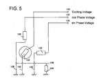
- prior art describes that in case that an exciting coil 122 , a cos phase coil 128 , and a sin phase coil 130 are grounded through a common earth wire 146 , the voltage which is made as a result that an alternating current bias voltage which is caused by an impedance 144 of the earth wire 146 and an exciting current, is superimposed on an alternating-current rotational angle voltage whose amplitude fluctuates in dependence on a sin value of a rotor rotational angle ⁇ is output to a terminal 136 of the sin phase coil 130 .
- a problem arises in that the detection accuracy of a rotor 122 rotational angle, which is gained from a voltage output from the terminal 136 of the sin phase coil 130 , is lowered.
- the prior art discloses the following rotational angle detection device.
- a steering wheel is slowly rotated through one revolution, during which the sin phase voltages are sampled to be stored in a RAM.
- four points of the one-cycle sin phase voltages are selected for data around the maximum peak value (at a 90-degree steering wheel angle) and around the maximum bottom value (at a 270-degree steering wheel angle), and then, those data are added in order.
- the bias voltage By dividing each value of these added data by numeral 2, only the bias voltage can be derived.
- a rotational angle voltage is calculated. And then, a rotational angle is derived from this rotational angle voltage.
- the present invention has been made aiming at the above unsolved problem in the prior art, and it is an object of the invention to provide a rotational angle detection device which is highly accurate not to involve the rotational angle error due to a temperature variation which varies every moment.
- the first invention resides in a rotational angle detection device having: a rotating rotor; an exciting coil secured to the rotor and having one end thereof to which an alternating-current exciting current is applied and the other end thereof connected to an earth wire; and a stator coil stationarily provided around the rotor and having one end thereof for taking out an output voltage and the other end thereof connected to the earth wire, the stator coil being for outputting the voltage which is made as a result that an alternating-current bias voltage, caused by an impedance of the earth wire and the exciting current, is superimposed on an alternating-current rotational angle voltage the amplitude of which fluctuates in dependence on the rotational angle of the rotor;
- the rotational angle detection device comprising: memory means for storing data necessary to calculate values of temperature-dependent components in connection with the passing time from a reference time; rotational angle voltage detection means for calculating the alternating-current rotational angle voltage by subtraction means for subtracting the data stored in the memory means; bias detection means for calculating the alternating-current bias voltage
- the output voltage which is made as a result that the alternating-current bias voltage, caused by the impedance of the earth wire and the exciting current, is superimposed on the alternating-current rotational angle voltage whose amplitude fluctuates in dependence on the rotational angle of the rotor, is generated at one end of the stator coil.
- the data memory means which stores the data necessary to calculate the values of the temperature-dependent components also stores data necessary to calculate the alternating-current rotational angle voltage and the alternating-current bias voltage in connection with the passing time from the reference time.
- the data memory means successively samples and stores the output voltages during the rotation of the rotor.
- the rotational angle voltage detection means subtracts the first output voltages and the second output voltages which are the same in the passing time from the reference time, of the data stored in the memory means by the subtraction means thereby to calculate the alternating-current rotational angle voltage.
- the bias detection means adds the first output voltages and the second output voltages which are the same in the passing time from the reference time, of the data stored in the memory means by the addition means thereby to calculate the alternating-current bias voltage.
- the amplitude value of the alternating-current rotational angle voltage calculated by the rotational angle voltage detection means, the phase difference of the alternating-current rotational angle voltage from the reference time, the amplitude value of the alternating-current bias voltage calculated by the bias detection means, and the phase difference of the alternating-current bias voltage from the reference time are calculated based on the values which are sampled at at least two different time points.
- the second invention is characterized by providing the rotational angle detection device according to the foregoing first invention with means for successively sampling and storing the output voltages during the rotation of the rotor; means for specifying first output voltages for at least one-cycle including the maximum peak value, from the output voltages being stored; means for specifying second output voltages for at least one-cycle including the maximum bottom value, from the output voltages being stored; and means for successively subtracting and adding the first output voltages and the second output voltages which are the same in the passing time from the reference time, of the specified first output voltages and the specified second output voltages.
- the rotational angle voltage at the electrical angle where the output voltage which is made as a result that the bias voltage is superimposed on the rotational angle voltage shows a peak value, the rotational angle voltage also shows a peak value, and at the electrical angle where the output voltage shows a bottom value, the rotational angle voltage also shows a bottom value. Therefore, the first output voltages for at least one cycle including the maximum peak value are specified from the memorized output voltages, and the second output voltages for at least one cycle including the maximum bottom value are specified from the memorized output voltages. Then, the alternating-current rotational angle voltage and the alternating-current bias voltage are calculated by successively subtracting and adding the first output voltages and the second output voltages which are the same in the passing time from the reference time.
- the third invention resides in a temperature compensation method for the temperature which affects an output voltage of a rotational angle detection device for outputting a voltage made as a result that an alternating-current bias voltage, caused by an impedance of an earth wire and an exciting current, is superimposed on an alternating-current rotational angle voltage whose amplitude fluctuates in dependence on the rotational angle of a rotor
- the temperature compensation method comprising: a first step of successively sampling the output voltages with the rotor being rotated; a second step of specifying first output voltages for at least one cycle in rotational angle including the maximum peak value, from the sampled output voltages; a third step of specifying second output voltages for at least one cycle in rotational angle including the maximum bottom value, from the sampled output voltages; a fourth step of calculating the alternating-current rotational angle voltage by successively subtracting the first and second output voltages which are same in the passing time from a reference time, of on the specified first output voltages and the specified second output voltages; a fifth
- the first output voltages for at least one cycle including the maximum peak value can be specified from the sampled output voltages.
- the second output voltages for at least one cycle including the maximum bottom value can also be specified from the sampled output voltages.
- the alternating-current rotational angle voltage can be calculated by successively subtracting the first output voltages and the second output voltages which are the same in the passing time from the reference time, of the specified first output voltages and the specified second output voltages.
- the alternating-current bias voltage can also be calculated by successively adding the first output voltages and the second output voltages which are the same in the passing time from the reference time, of the specified first output voltages and the specified second output voltages.
- the amplitude value of the alternating-current rotational angle voltage, the phase difference of the alternating-current rotational angle voltage from the reference time, the amplitude value of the alternating-current bias voltage, and the phase difference of the alternating-current bias voltage from the reference time can be calculated based on the values which are sampled at at least two different time points from the alternating-current rotational angle voltage and the alternating-current bias voltage.
- the rotational angle detection device which is highly accurate not to be affected by the temperature fluctuating every moment can be obtained by utilizing the calculated amplitude value and phase difference of the alternating-current rotational angle voltage and the calculated amplitude value and phase difference of the alternating-current bias voltage.
- FIG. 1 is a structure diagram illustrating an electric power steering system to which a torque detection device in an embodiment of the present invention is applied;
- FIG. 2 is a block diagram illustrating a torque detection device
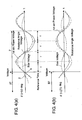
- FIG. 3 is a graph showing an output voltage obtained when a rotor rotates 360-degrees in electrical angle
- FIG. 4 is a diagram illustrating the maximum peak value, the maximum bottom value, and each voltage wave.
- FIG. 5 is a block diagram illustrating a rotational angle detection device constituting a prior art.
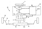
- FIG. 1 The structure of an electric power steering system 10 , to which the present invention is applied, is shown in FIG. 1 .
- This system 10 comprises a first rotational angle detection device mainly composed of an ECU 20 and a first resolver 15 s and a second rotational angle detection device composed of the ECU 20 and a second resolver 16 s . Further, the ECU 20 , the first resolver 15 s and the second resolver 16 s constitute a torque detection device for converting the driver's handle steering into a torque value thereby to detect the same.
- a handle 11 is connected with one end of a handle shaft 12
- one end of a torsion bar 14 is connected with the other end of the handle shaft 12 .
- the other end of the torsion bar 14 is connected with a pinion shaft 13 via an output shaft.
- a pinion of the pinion shaft 13 is meshing with a rack 19 .
- the rack 19 and a rack housing 18 H compose a rack mechanism 18 .
- the rack mechanism 18 is constituted to reciprocate the rack 19 axially inside of the rack housing 18 H. Both ends of the rack mechanism 18 have respective one ends of tie rods 21 attached thereto. Other ends of the tie rods 21 are connected with respective one ends of knuckle arms 22 . Other ends of the knuckle arms 22 are connected with wheels 23 .
- the first resolver 15 s is provided around a lower end of the aforementioned handle shaft 12 .
- the first resolver 15 s functions as a first rotational angle detection portion for detecting a first rotational angle ⁇ 1 regarding the handle shaft 12 .
- the second resolver 16 s is provided around a lower end of the torsion bar 14 .
- the second resolver 16 s functions as a second rotational angle detection portion for detecting a second rotation angle ⁇ 2 regarding the pinion 13 .
- the first resolver 15 s and the second resolver 16 s are electrically connected with the ECU 20 .
- a torque detection device 30 is composed of the ECU 20 , the first resolver 15 s and the second resolver 16 s .
- Symbol K T is a spring constant of the torsion bar 14 .
- the ECU 20 is connected with a motor M, converts the calculated torque value T into a command current by reference to a predetermined torque/current value conversion map, and executes PWM (Pulse Width Modulation) control through a current control section. More concrete constructions of the torque detection devices 30 , 15 s , 16 s will be described later.
- the motor M transmits the generated assist torque to the rack mechanism 18 via a reduction gear 17 .
- this electric power steering system 10 will be described. First, when the driver steers the handle 11 , the handle shaft 12 is rotated. When the handle shaft 12 is rotated, the pinion shaft 13 is also rotated via the torsion bar 14 . When the pinion shaft 13 is rotated, the rack 19 meshing with the pinion is moved axially, and the traveling direction of the wheels 23 is varied via the tie rods 21 and the knuckle arms 22 . The torque generated from the steering action by the driver of the handle 11 is detected by the torque detection devices 30 , 15 s , 16 s . The ECU 20 composing the torque detection device controls the motor M in dependence on the detected torque.
- the ECU 20 controls the motor M to generate a small assist torque.
- the ECU 20 controls the motor M to generate a large assist torque.
- the assist torque generated by the motor M is transmitted to the rack mechanism 18 to assist the movement of the rack 19 . Therefore, the driver can steer the handle 11 with a small power.
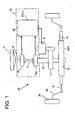
- the block diagram of the torque detection device 30 is shown in FIG. 2 .
- the torque detection device 30 includes the first rotational angle detection device composed with the ECU 20 and the first resolver 15 s and the second rotational angle detection device composed with the ECU 20 and the second resolver 16 s .
- the ECU 20 is composed of a CPU 52 and a ROM 56 , a RAM 58 and an EEPROM (Electrically Erasable Programmable ROM) 59 which are connected to the CPU 52 via an internal bus 53 .
- the CPU 52 has ports such as input ports 52 b - 52 e , an output port 52 a , etc.
- the input ports 52 b - 52 e are connected with an analog to digital converter inside of the CPU 52 , so that any analog signal is converted into a digital signal to be processed in the CPU 52 .
- the output port 52 a is connected with a digital to analog converter inside of the CPU 52 , so that a digital signal is converted into an analog signal to be output to the first resolver 15 s , the second resolver 16 s , and the motor M.
- the ROM 56 has stored therein a program for executing the derivation processing of temperature compensation described later; another program for torque calculation and the like.
- the first resolver 15 s is provided with a first rotor 31 , a first exciting coil 32 , a first sin phase coil (stator coil) 34 , a first cos phase coil (stator coil) 36 , etc.
- the second resolver 16 s is provided with a second rotor 41 , a second exciting coil 42 , a second sin phase coil (stator coil) 43 , a second cos phase coil (stator coil) 44 , etc.
- the first rotor 31 has the first exciting coil 32 . When the first rotor 31 is rotated, the first exciting coil 32 is also rotated.
- the rotor coils are arranged to gain the electrical angle which is four times as large as the mechanical rotational angle of the first rotor 31 .
- the electrical angle there are provided four pairs of the south poles and the north poles, and the resolution of the rotational angle is increased to four times since the increase in speed which may otherwise be performed mechanically by the use of a number of gears or the like in general is performed electrically.
- the term “rotational angle” referred to hereafter means the electrical angle unless specified to the contrary.
- the first exciting coil 32 of the first resolver 15 s is wound in a slot of the first rotor 31 .
- One end of this first exciting coil 32 has an alternating-current exciting voltage (equation (1) described later) applied thereto from the output port 52 a of the CPU 52 , and the other end thereof is connected with a common earth wire 46 .
- the second exciting coil 42 of the second resolver 16 s is wound in a slot of the second rotor 41 .
- This second exciting coil 42 also has at its one end an alternating-current exciting voltage (equation (1) described later) applied thereto from the output port 52 a of the CPU 52 , and is connected with the common earth wire 46 at the other end thereof.
- the exciting coils 32 and 42 compose a transformer in combination with coils (not shown) which are built in the rotors 31 and 41 .
- the voltage generated in the coils which are not shown are applied as exciting voltages respectively to the exciting coils 32 and 42 .
- a contactless-type transformer is described as means for applying exciting voltages to the exciting coils 32 and 42 of the first rotor 31 and the second rotor 41 from the outside, a contact-type brush may be used in substitution therefor.
- the exciting voltage is expressed by the following equation (1).
- Ve E sin ⁇ t
- the exciting current is expressed by the following equation (2).
- Ie I sin( ⁇ t + ⁇ ) (2) Symbols in these equations represent the followings: E is the amplitude of the exciting voltage (volt), ⁇ is the angle speed of the exciting voltage (rad/s), I is the amplitude of the exciting current (amp), and ⁇ is the phase difference of the exciting current from the exciting voltage.
- the first cos phase coil 36 of the first resolver 15 s is wound in a slot of a stator which is fixed around the first rotor 31 in coaxial alignment with the same.
- This first cos phase coil 36 is connected to the input port 52 b of the CPU 52 so that the first cos phase voltage generated at one end thereof is input to the input port 52 b of the CPU 52 , and is further connected to the common earth wire 46 at the other end thereof.
- the first cos phase voltage (expressed by equation (5) referred to later) is the voltage which is made as a result that an alternating-current bias voltage (expressed by equation (4) referred to later) which depends on an impedance 48 of the common earth wire 46 and the exciting current is superimposed on an alternating-current rotational angle voltage (expressed by equation (3) referred to later) whose amplitude fluctuates in dependence on a cos value at the rotational angle ⁇ 1 of the first rotor 31 .
- the rotational angle voltage of the first cos phase voltage is expressed by the following equation (3).
- V cos 1 EK ( T ) sin( ⁇ t + ⁇ ( T )) cos ( ⁇ 1 ) (3)
- the bias voltage is expressed by the following equation (4).
- V bias R ( T ) I sin( ⁇ t + ⁇ ( T )) (4)
- the first cos phase voltage is expressed by the following equation (5) which is obtained by adding the equation (3) and the equation (4).
- V cos 1 T EK ( T ) sin( ⁇ t + ⁇ ( T )) cos ( ⁇ 1 )+ R ( T ) I sin( ⁇ t + ⁇ ( T )) (5)
- K(T) is the transformer efficiency (no unit)
- ⁇ (T) is the phase difference of the first cos phase voltage from the exciting voltage (rad)
- ⁇ 1 is the first rotational angle of the first rotor (rad)
- R(T) is the impedance ( ⁇ ) of the common earth wire.
- each symbol with suffix (T) means that the state of the parameter represented by the symbol varies in dependence on the temperature.
- the first sin phase coil 34 of the first resolver 15 s is wound in a slot of the stator which is fixed around the first rotor 31 in coaxial alignment therewith, with a phase difference of 90-electrical angles form the aforementioned first cos phase coil 36 .
- the first sin phase coil 34 is connected to the input port 52 c of the CPU 52 so that the first sin phase voltage generated at one end thereof is input to the input port 52 c of the CPU 52 , and is further connected to the common earth wire 46 at the other end thereof.
- the first sin phase voltage (expressed by equation (7) referred to later) is the voltage which is made as a result that the alternating-current bias voltage (expressed by the aforementioned equation (4)) which depends on the impedance 48 of the common earth wire 46 and the exciting current is superimposed on an alternating-current rotational angle voltage (expressed by equation (6) referred to later) whose amplitude fluctuates in dependence on the sin value at the rotational angle ⁇ 1 of the first rotor 31 .
- the rotational angle voltage of the first sin phase voltage is expressed by the following equation (6).
- V sin 1 EK ( T ) sin( ⁇ t + ⁇ ( T )) sin( ⁇ 1 ) (6)
- the first sin phase voltage is expressed by the following equation (7) which is obtained by adding the equation (6) and the equation (4).
- V sin 1 T EK ( T ) sin( ⁇ t + ⁇ ( T )) sin( ⁇ 1 )+ R ( T ) I sin( ⁇ t + ⁇ ( T )) (7)
- the symbols used in these equations are the same as those described in connection with the equations (1) to (5).
- the second cos phase coil 44 and the second sin phase coil 43 of the second resolver 16 s are also connected with the common earth wire 46 . Since other basic configuration of the second resolver 16 s is the same as that of the first resolver 15 s , further description thereof will be omitted.
- the first exciting coil 31 , the first cos phase coil 36 and the first sin phase coil 34 of the first resolver 15 s and the second exciting coil 42 , the second cos phase coil 44 and the second sin phase coil 43 of the second resolver 16 s are connected with the common earth wire 46 to be grounded.
- the number of wirings can be reduced substantially compared with the manner wherein they may be connected to six separated earth wires.
- the compensation processing is executed on a real time basis, it may of course be executed at a certain time interval or may be executed when there is given a trigger or the like for the processing starting of the temperature compensation.
- the driver rotates the handle 11 illustrated in FIG. 1 thereby to rotate the electrical angle ⁇ 1 of the first rotor 31 from 0 to 360 degrees. While the rotating operation is performed, the CPU 52 samples the first sin phase voltages of the first resolver 15 s at a sampling interval of 50 ⁇ s and stores the data in the RAM 58 .
- the CPU 52 performs a processing for detecting the voltage data including the maximum peak value, of the first sin voltage data.
- the rotational angle voltage also shows the peak value.
- the rotational angle voltage shows the peak value.
- a sampling is performed for the voltage data which are included within the range of 89.5 through 90.5 degrees (i.e., 1 degree) in electric angle ⁇ 1 .
- the data in the range L 1 shown in FIG. 3 are sampled.
- the CPU 52 performs a processing for detecting the voltage data including the maximum bottom value, of the first sin voltage data.
- the rotational angle voltage also shows the bottom value.
- the rotational angle voltage shows the bottom value.
- a sampling is performed for the voltage data which are included within the range of 269.5 through 270.5 degrees (i.e., 1 degree) of the electrical angle ⁇ 1 .
- the data in the range L 2 shown in FIG. 3 are sampled.
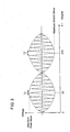
- FIGS. 4 ( a ) and 4 ( b ) are graphs each setting the horizontal axis and the vertical axis as time and voltage respectively.
- FIG. 4 ( a ) shows those data around the maximum peak value of the first sin phase voltages, and the rotational angle voltages and the bias voltages which compose such those data.
- FIG. 4 ( b ) shows those data around the maximum bottom value of the first sin phase voltages, and the rotational angle voltages and the bias voltages which compose such those data.
- FIGS. 4 ( a ) and 4 ( b ) are graphs in which the range L 1 and the range L 2 on the time axis shown in FIG. 3 are drawn in an enlarged scale. A symbol P in FIG.
- FIG. 4 designates the cycle of the first sin phase voltage, and the cycle is set to 200 ⁇ s in the present embodiment.
- Another symbol ⁇ in FIG. 4 designates the interval for the first sin phase voltages to be sampled by the CPU 52 , and the interval is set to 50 ⁇ s in the present embodiment.
- the mutual data which are the same in the passing time from a reference time are subtracted in order from each other.
- the reference time is taken as a time point reached when a period which is integer times as long as the cycle P expires from a time point for application of the exciting voltage.
- a rotational angle voltage including a temperature component is calculated by dividing each subtracted value by numeral 2.
- Two time points to be multiplied with the rotational angle velocity which composes the rotational angular voltage calculated in the foregoing means are chosen, and rotational angular voltage values at such time points are taken out. This determines the values of two parameters each including the temperature component and composing the rotational angle voltage. Further, two time points to be multiplied with the rotational angle velocity which composes the bias voltage calculated in the foregoing means are chosen, and bias voltage values at such time points are taken out. This determines the values of two parameters each including the temperature component and composing the bias voltage.
- V sin 1T is the value which is taken into the CPU 52 via an input port as the first sin phase voltage.
- E, ⁇ , and I are those memorized in EEPROM 62 , and the temperature-dependant components K(T), ⁇ (T), R(T) and ⁇ (T) have also been calculated through the foregoing calculations.
- resolver has been shown to be of the construction having one exciting coil at the rotor side and two output coils at the stator side, the present invention may of course be applicable to a resolver of the construction having two exciting coils at the stator side and one or two output coils at the rotor side.
- the rotational angle detection device and the temperature compensation method thereof according to the present invention are suitable for use in an automotive electric power steering apparatus which converts the rotation of a steering wheel by the driver to the axial motion of a rack shaft through a rack and pinion mechanism and which assists the axial motion of the rack shaft with a steering force amplified by an electric motor so that the orientation of wheels is controlled via tie rods and knuckle arms.
Landscapes
- Physics & Mathematics (AREA)
- General Physics & Mathematics (AREA)
- Transmission And Conversion Of Sensor Element Output (AREA)
- Measurement Of Length, Angles, Or The Like Using Electric Or Magnetic Means (AREA)
- Power Steering Mechanism (AREA)
Abstract
Description
- The present invention relates to a rotational angle detection device and a temperature compensation method therefor, and in particular, it relates to a derivation method therefor.
- For example, as a rotational angle detection device for detecting the rotational angle by means of a conventional resolver, there is a rotational angle detection device, which is described in Japanese Patent Application No. 2002-127173 (hereafter referred to as “prior art”). As shown in
FIG. 5 , prior art describes that in case that anexciting coil 122, acos phase coil 128, and asin phase coil 130 are grounded through acommon earth wire 146, the voltage which is made as a result that an alternating current bias voltage which is caused by animpedance 144 of theearth wire 146 and an exciting current, is superimposed on an alternating-current rotational angle voltage whose amplitude fluctuates in dependence on a sin value of a rotor rotational angle θ is output to aterminal 136 of thesin phase coil 130. As a result, a problem arises in that the detection accuracy of arotor 122 rotational angle, which is gained from a voltage output from theterminal 136 of thesin phase coil 130, is lowered. To solve this problem, the prior art discloses the following rotational angle detection device. First, a steering wheel is slowly rotated through one revolution, during which the sin phase voltages are sampled to be stored in a RAM. Then, from the stored data in the RAM, four points of the one-cycle sin phase voltages are selected for data around the maximum peak value (at a 90-degree steering wheel angle) and around the maximum bottom value (at a 270-degree steering wheel angle), and then, those data are added in order. By dividing each value of these added data by numeral 2, only the bias voltage can be derived. By subtracting this bias voltage from the sin phase voltage, a rotational angle voltage is calculated. And then, a rotational angle is derived from this rotational angle voltage. - However, in the prior art, sufficient consideration is not given regarding a temperature variation which varies every moment. For example, a problem remains unsolved in that the rotational angle cannot be detected accurately for the following reason. That is, a resistance value of the
impedance 144 has a temperature drift due to a variation in the ambient temperature, and as a result, the output voltage from theterminal 136 of thesin phase coil 130 also has a temperature drift. - Accordingly, the present invention has been made aiming at the above unsolved problem in the prior art, and it is an object of the invention to provide a rotational angle detection device which is highly accurate not to involve the rotational angle error due to a temperature variation which varies every moment.
- The first invention resides in a rotational angle detection device having: a rotating rotor; an exciting coil secured to the rotor and having one end thereof to which an alternating-current exciting current is applied and the other end thereof connected to an earth wire; and a stator coil stationarily provided around the rotor and having one end thereof for taking out an output voltage and the other end thereof connected to the earth wire, the stator coil being for outputting the voltage which is made as a result that an alternating-current bias voltage, caused by an impedance of the earth wire and the exciting current, is superimposed on an alternating-current rotational angle voltage the amplitude of which fluctuates in dependence on the rotational angle of the rotor; the rotational angle detection device comprising: memory means for storing data necessary to calculate values of temperature-dependent components in connection with the passing time from a reference time; rotational angle voltage detection means for calculating the alternating-current rotational angle voltage by subtraction means for subtracting the data stored in the memory means; bias detection means for calculating the alternating-current bias voltage by addition means for adding the data stored in the memory means; and means for calculating an amplitude value of the alternating-current rotational angle voltage, a phase difference of the alternating-current rotational angle voltage from the reference time, an amplitude value of the alternating-current bias voltage, and a phase difference of the alternating-current bias voltage from the reference time, based on values sampled by the rotational angle voltage detection means and the bias detection means at at least two different time points
- According to the first invention, when the rotor rotates relative to the stator coil, the output voltage which is made as a result that the alternating-current bias voltage, caused by the impedance of the earth wire and the exciting current, is superimposed on the alternating-current rotational angle voltage whose amplitude fluctuates in dependence on the rotational angle of the rotor, is generated at one end of the stator coil. The data memory means which stores the data necessary to calculate the values of the temperature-dependent components also stores data necessary to calculate the alternating-current rotational angle voltage and the alternating-current bias voltage in connection with the passing time from the reference time. The data memory means successively samples and stores the output voltages during the rotation of the rotor. The rotational angle voltage detection means subtracts the first output voltages and the second output voltages which are the same in the passing time from the reference time, of the data stored in the memory means by the subtraction means thereby to calculate the alternating-current rotational angle voltage. The bias detection means adds the first output voltages and the second output voltages which are the same in the passing time from the reference time, of the data stored in the memory means by the addition means thereby to calculate the alternating-current bias voltage. The amplitude value of the alternating-current rotational angle voltage calculated by the rotational angle voltage detection means, the phase difference of the alternating-current rotational angle voltage from the reference time, the amplitude value of the alternating-current bias voltage calculated by the bias detection means, and the phase difference of the alternating-current bias voltage from the reference time are calculated based on the values which are sampled at at least two different time points. By using the amplitude value of the alternating-current rotational angle voltage, the phase difference of the alternating-current rotational angle voltage from the reference time, the amplitude value of the alternating-current bias voltage, and the phase difference of the alternating-current bias voltage from the reference time, the rotational angle can be detected accurately without suffering the influence of the temperature varying every moment.
- The second invention is characterized by providing the rotational angle detection device according to the foregoing first invention with means for successively sampling and storing the output voltages during the rotation of the rotor; means for specifying first output voltages for at least one-cycle including the maximum peak value, from the output voltages being stored; means for specifying second output voltages for at least one-cycle including the maximum bottom value, from the output voltages being stored; and means for successively subtracting and adding the first output voltages and the second output voltages which are the same in the passing time from the reference time, of the specified first output voltages and the specified second output voltages.
- According to the second invention, at the electrical angle where the output voltage which is made as a result that the bias voltage is superimposed on the rotational angle voltage shows a peak value, the rotational angle voltage also shows a peak value, and at the electrical angle where the output voltage shows a bottom value, the rotational angle voltage also shows a bottom value. Therefore, the first output voltages for at least one cycle including the maximum peak value are specified from the memorized output voltages, and the second output voltages for at least one cycle including the maximum bottom value are specified from the memorized output voltages. Then, the alternating-current rotational angle voltage and the alternating-current bias voltage are calculated by successively subtracting and adding the first output voltages and the second output voltages which are the same in the passing time from the reference time.
- Further, the third invention resides in a temperature compensation method for the temperature which affects an output voltage of a rotational angle detection device for outputting a voltage made as a result that an alternating-current bias voltage, caused by an impedance of an earth wire and an exciting current, is superimposed on an alternating-current rotational angle voltage whose amplitude fluctuates in dependence on the rotational angle of a rotor, the temperature compensation method comprising: a first step of successively sampling the output voltages with the rotor being rotated; a second step of specifying first output voltages for at least one cycle in rotational angle including the maximum peak value, from the sampled output voltages; a third step of specifying second output voltages for at least one cycle in rotational angle including the maximum bottom value, from the sampled output voltages; a fourth step of calculating the alternating-current rotational angle voltage by successively subtracting the first and second output voltages which are same in the passing time from a reference time, of on the specified first output voltages and the specified second output voltages; a fifth step of calculating the alternating-current bias voltage by successively adding the first output voltages and the second output voltages, which are the same in the passing time from the reference time, of the specified first output voltages and the specified second output voltages; and a sixth step of calculating an amplitude value of the alternating-current rotational angle voltage, a phase difference of the alternating-current rotational angle voltage from the reference time, an amplitude value of the alternating-current bias voltage, and a phase difference of the alternating-current bias voltage from the reference time, based on values which have been sampled at at least two different time points at the fourth step and the fifth step.
- According to the temperature compensation method relating to the third invention, by successively sampling the output voltages with the rotor being rotated, the first output voltages for at least one cycle including the maximum peak value can be specified from the sampled output voltages. The second output voltages for at least one cycle including the maximum bottom value can also be specified from the sampled output voltages. The alternating-current rotational angle voltage can be calculated by successively subtracting the first output voltages and the second output voltages which are the same in the passing time from the reference time, of the specified first output voltages and the specified second output voltages. The alternating-current bias voltage can also be calculated by successively adding the first output voltages and the second output voltages which are the same in the passing time from the reference time, of the specified first output voltages and the specified second output voltages. The amplitude value of the alternating-current rotational angle voltage, the phase difference of the alternating-current rotational angle voltage from the reference time, the amplitude value of the alternating-current bias voltage, and the phase difference of the alternating-current bias voltage from the reference time can be calculated based on the values which are sampled at at least two different time points from the alternating-current rotational angle voltage and the alternating-current bias voltage. The rotational angle detection device which is highly accurate not to be affected by the temperature fluctuating every moment can be obtained by utilizing the calculated amplitude value and phase difference of the alternating-current rotational angle voltage and the calculated amplitude value and phase difference of the alternating-current bias voltage.
-
FIG. 1 is a structure diagram illustrating an electric power steering system to which a torque detection device in an embodiment of the present invention is applied; -
FIG. 2 is a block diagram illustrating a torque detection device; -
FIG. 3 is a graph showing an output voltage obtained when a rotor rotates 360-degrees in electrical angle; -
FIG. 4 is a diagram illustrating the maximum peak value, the maximum bottom value, and each voltage wave; and -
FIG. 5 is a block diagram illustrating a rotational angle detection device constituting a prior art. - The structure of an electric
power steering system 10, to which the present invention is applied, is shown inFIG. 1 . Thissystem 10 comprises a first rotational angle detection device mainly composed of anECU 20 and afirst resolver 15 s and a second rotational angle detection device composed of theECU 20 and asecond resolver 16 s. Further, the ECU 20, thefirst resolver 15 s and thesecond resolver 16 s constitute a torque detection device for converting the driver's handle steering into a torque value thereby to detect the same. In this electricpower steering system 10, ahandle 11 is connected with one end of ahandle shaft 12, and one end of atorsion bar 14 is connected with the other end of thehandle shaft 12. The other end of thetorsion bar 14 is connected with apinion shaft 13 via an output shaft. A pinion of thepinion shaft 13 is meshing with arack 19. Therack 19 and arack housing 18H compose arack mechanism 18. Therack mechanism 18 is constituted to reciprocate therack 19 axially inside of therack housing 18H. Both ends of therack mechanism 18 have respective one ends oftie rods 21 attached thereto. Other ends of thetie rods 21 are connected with respective one ends ofknuckle arms 22. Other ends of theknuckle arms 22 are connected withwheels 23. - The
first resolver 15 s is provided around a lower end of theaforementioned handle shaft 12. Thefirst resolver 15 s functions as a first rotational angle detection portion for detecting a first rotational angle θ1 regarding thehandle shaft 12. Thesecond resolver 16 s is provided around a lower end of thetorsion bar 14. Thesecond resolver 16 s functions as a second rotational angle detection portion for detecting a second rotation angle θ2 regarding thepinion 13. Thefirst resolver 15 s and thesecond resolver 16 s are electrically connected with the ECU 20. Atorque detection device 30 is composed of the ECU 20, thefirst resolver 15 s and thesecond resolver 16 s. TheECU 20 composing the torque detection device calculates a steering torque value T=KT(θ1−θ2) which the driver generates by steering thehandle 11, based on the first rotational angle θ1 detected by thefirst resolver 15 s and the second rotational angle θ2 detected by thesecond resolver 16 s. Symbol KT is a spring constant of thetorsion bar 14. TheECU 20 is connected with a motor M, converts the calculated torque value T into a command current by reference to a predetermined torque/current value conversion map, and executes PWM (Pulse Width Modulation) control through a current control section. More concrete constructions of thetorque detection devices rack mechanism 18 via areduction gear 17. - The operation of this electric
power steering system 10 will be described. First, when the driver steers thehandle 11, thehandle shaft 12 is rotated. When thehandle shaft 12 is rotated, thepinion shaft 13 is also rotated via thetorsion bar 14. When thepinion shaft 13 is rotated, therack 19 meshing with the pinion is moved axially, and the traveling direction of thewheels 23 is varied via thetie rods 21 and theknuckle arms 22. The torque generated from the steering action by the driver of thehandle 11 is detected by thetorque detection devices ECU 20 composing the torque detection device controls the motor M in dependence on the detected torque. - When the steering torque detected by the
torque detection device 30 is small, theECU 20 controls the motor M to generate a small assist torque. When the steering torque detected by thetorque detection device 30 is large, theECU 20 controls the motor M to generate a large assist torque. The assist torque generated by the motor M is transmitted to therack mechanism 18 to assist the movement of therack 19. Therefore, the driver can steer thehandle 11 with a small power. - The block diagram of the
torque detection device 30 is shown inFIG. 2 . As described above, thetorque detection device 30 includes the first rotational angle detection device composed with theECU 20 and thefirst resolver 15 s and the second rotational angle detection device composed with theECU 20 and thesecond resolver 16 s. TheECU 20 is composed of aCPU 52 and aROM 56, aRAM 58 and an EEPROM (Electrically Erasable Programmable ROM) 59 which are connected to theCPU 52 via aninternal bus 53. TheCPU 52 has ports such asinput ports 52 b-52 e, anoutput port 52 a, etc. Theinput ports 52 b-52 e are connected with an analog to digital converter inside of theCPU 52, so that any analog signal is converted into a digital signal to be processed in theCPU 52. Besides, theoutput port 52 a is connected with a digital to analog converter inside of theCPU 52, so that a digital signal is converted into an analog signal to be output to thefirst resolver 15 s, thesecond resolver 16 s, and the motorM. The ROM 56 has stored therein a program for executing the derivation processing of temperature compensation described later; another program for torque calculation and the like. - The
first resolver 15 s is provided with afirst rotor 31, a firstexciting coil 32, a first sin phase coil (stator coil) 34, a first cos phase coil (stator coil) 36, etc. Thesecond resolver 16 s is provided with asecond rotor 41, a secondexciting coil 42, a second sin phase coil (stator coil) 43, a second cos phase coil (stator coil) 44, etc. Thefirst rotor 31 has the firstexciting coil 32. When thefirst rotor 31 is rotated, the firstexciting coil 32 is also rotated. In the preferred embodiment, although not illustrated concretely, for higher detection accuracy of rotational angle, the rotor coils are arranged to gain the electrical angle which is four times as large as the mechanical rotational angle of thefirst rotor 31. To make the electrical angle four times, there are provided four pairs of the south poles and the north poles, and the resolution of the rotational angle is increased to four times since the increase in speed which may otherwise be performed mechanically by the use of a number of gears or the like in general is performed electrically. The term “rotational angle” referred to hereafter means the electrical angle unless specified to the contrary. - The first
exciting coil 32 of thefirst resolver 15 s is wound in a slot of thefirst rotor 31. One end of this firstexciting coil 32 has an alternating-current exciting voltage (equation (1) described later) applied thereto from theoutput port 52 a of theCPU 52, and the other end thereof is connected with acommon earth wire 46. Further, the secondexciting coil 42 of thesecond resolver 16 s is wound in a slot of thesecond rotor 41. This secondexciting coil 42 also has at its one end an alternating-current exciting voltage (equation (1) described later) applied thereto from theoutput port 52 a of theCPU 52, and is connected with thecommon earth wire 46 at the other end thereof. Therefore, the total current of the first exciting current passing through the firstexciting coil 32 and the second exciting current passing through the secondexciting coil 42 passes through thecommon earth wire 46. Hereafter, the total current of the first exciting current and the second exciting current will be referred to simply as “exciting current”. The exciting coils 32 and 42 compose a transformer in combination with coils (not shown) which are built in therotors exciting coils exciting coils first rotor 31 and thesecond rotor 41 from the outside, a contact-type brush may be used in substitution therefor. - The exciting voltage is expressed by the following equation (1).
Ve=E sin ωt (1)
The exciting current is expressed by the following equation (2).
Ie=I sin(ωt+β) (2)
Symbols in these equations represent the followings: E is the amplitude of the exciting voltage (volt), ω is the angle speed of the exciting voltage (rad/s), I is the amplitude of the exciting current (amp), and β is the phase difference of the exciting current from the exciting voltage. The angle speed ω of the exciting voltage has a relationship of ω=2π/P, and P in this case is the cycle (s). In the preferred example, P is set to 200 μs. - The first
cos phase coil 36 of thefirst resolver 15 s is wound in a slot of a stator which is fixed around thefirst rotor 31 in coaxial alignment with the same. This firstcos phase coil 36 is connected to theinput port 52 b of theCPU 52 so that the first cos phase voltage generated at one end thereof is input to theinput port 52 b of theCPU 52, and is further connected to thecommon earth wire 46 at the other end thereof. The first cos phase voltage (expressed by equation (5) referred to later) is the voltage which is made as a result that an alternating-current bias voltage (expressed by equation (4) referred to later) which depends on animpedance 48 of thecommon earth wire 46 and the exciting current is superimposed on an alternating-current rotational angle voltage (expressed by equation (3) referred to later) whose amplitude fluctuates in dependence on a cos value at the rotational angle θ1 of thefirst rotor 31. - The rotational angle voltage of the first cos phase voltage is expressed by the following equation (3).
V cos 1=EK(T) sin(ωt+α(T)) cos (θ1) (3)
The bias voltage is expressed by the following equation (4).
Vbias=R(T)I sin(ωt+β(T)) (4)
The first cos phase voltage is expressed by the following equation (5) which is obtained by adding the equation (3) and the equation (4).
V cos 1T=EK(T) sin(ωt+α(T)) cos (θ1)+R(T)I sin(ωt+α(T)) (5)
Symbols in these equations represent the followings: K(T) is the transformer efficiency (no unit), α(T) is the phase difference of the first cos phase voltage from the exciting voltage (rad), θ1 is the first rotational angle of the first rotor (rad), and R(T) is the impedance (Ω) of the common earth wire. Further, each symbol with suffix (T) means that the state of the parameter represented by the symbol varies in dependence on the temperature. - Next, the first
sin phase coil 34 of thefirst resolver 15 s is wound in a slot of the stator which is fixed around thefirst rotor 31 in coaxial alignment therewith, with a phase difference of 90-electrical angles form the aforementioned firstcos phase coil 36. The firstsin phase coil 34 is connected to theinput port 52 c of theCPU 52 so that the first sin phase voltage generated at one end thereof is input to theinput port 52 c of theCPU 52, and is further connected to thecommon earth wire 46 at the other end thereof. The first sin phase voltage (expressed by equation (7) referred to later) is the voltage which is made as a result that the alternating-current bias voltage (expressed by the aforementioned equation (4)) which depends on theimpedance 48 of thecommon earth wire 46 and the exciting current is superimposed on an alternating-current rotational angle voltage (expressed by equation (6) referred to later) whose amplitude fluctuates in dependence on the sin value at the rotational angle θ1 of thefirst rotor 31. - The rotational angle voltage of the first sin phase voltage is expressed by the following equation (6).
V sin 1=EK(T) sin(ωt+α(T)) sin(θ1) (6)
The first sin phase voltage is expressed by the following equation (7) which is obtained by adding the equation (6) and the equation (4).
V sin 1T=EK(T) sin(ωt+α(T)) sin(θ1)+R(T)I sin(ωt+α(T)) (7)
The symbols used in these equations are the same as those described in connection with the equations (1) to (5). - The second
cos phase coil 44 and the secondsin phase coil 43 of thesecond resolver 16 s are also connected with thecommon earth wire 46. Since other basic configuration of thesecond resolver 16 s is the same as that of thefirst resolver 15 s, further description thereof will be omitted. - In this manner, the first
exciting coil 31, the firstcos phase coil 36 and the firstsin phase coil 34 of thefirst resolver 15 s and the secondexciting coil 42, the secondcos phase coil 44 and the secondsin phase coil 43 of thesecond resolver 16 s are connected with thecommon earth wire 46 to be grounded. Thus, the number of wirings can be reduced substantially compared with the manner wherein they may be connected to six separated earth wires. - Next, description will be made regarding a processing content for making a compensation for the influence of the temperature by the use of the
torque detection device 30 in the present embodiment. Although in the present embodiment, the compensation processing is executed on a real time basis, it may of course be executed at a certain time interval or may be executed when there is given a trigger or the like for the processing starting of the temperature compensation. - First, it is now assumed that after beginning of applying the exciting voltage, the driver rotates the
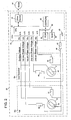
handle 11 illustrated inFIG. 1 thereby to rotate the electrical angle θ1 of thefirst rotor 31 from 0 to 360 degrees. While the rotating operation is performed, theCPU 52 samples the first sin phase voltages of thefirst resolver 15 s at a sampling interval of 50 μs and stores the data in theRAM 58. - Where the sampled data of the first sin phase voltages are plotted with the horizontal axis and the vertical axis indicating the rotational angle θ1 and the voltage value respectively, there is drawn an alternating-current waveform the amplitude of which fluctuates in dependence on sin(θ1) as shown in
FIG. 3 . However, the waveform actually becomes a waveform whose wavelength is much shorter than that shown inFIG. 3 . For example, assuming that the rotational frequency of the exciting voltage is 5 kHz, the cycle of the first sin phase voltage becomes 200 μs, and then assuming that it takes one second for the handle to be actually rotated through one revolution in electrical angle, the waveforms of 5,000 pulses are included in one cycle of the handle. - The
CPU 52 performs a processing for detecting the voltage data including the maximum peak value, of the first sin voltage data. At the electrical angle where the output voltage which is made as a result that the bias voltage is superimposed on the rotational angle voltage shows the peak value, the rotational angle voltage also shows the peak value. At sin(θ1)=1, that is, the electrical angle θ1=90 degrees, the rotational angle voltage shows the peak value. In the present embodiment, a sampling is performed for the voltage data which are included within the range of 89.5 through 90.5 degrees (i.e., 1 degree) in electric angle θ1. In an imaginary sense, the data in the range L1 shown inFIG. 3 are sampled. Further, theCPU 52 performs a processing for detecting the voltage data including the maximum bottom value, of the first sin voltage data. At the electrical angle where the output voltage which is made as a result that the bias voltage is superimposed on the rotational angle voltage shows the bottom value, the rotational angle voltage also shows the bottom value. At sin(θ1)=−1, that is, the electrical angle θ1=270 degrees, the rotational angle voltage shows the bottom value. In the present embodiment, a sampling is performed for the voltage data which are included within the range of 269.5 through 270.5 degrees (i.e., 1 degree) of the electrical angle θ1. In an imaginary sense, the data in the range L2 shown inFIG. 3 are sampled. - FIGS. 4(a) and 4(b) are graphs each setting the horizontal axis and the vertical axis as time and voltage respectively.
FIG. 4 (a) shows those data around the maximum peak value of the first sin phase voltages, and the rotational angle voltages and the bias voltages which compose such those data.FIG. 4 (b) shows those data around the maximum bottom value of the first sin phase voltages, and the rotational angle voltages and the bias voltages which compose such those data. FIGS. 4(a) and 4(b) are graphs in which the range L1 and the range L2 on the time axis shown inFIG. 3 are drawn in an enlarged scale. A symbol P inFIG. 4 designates the cycle of the first sin phase voltage, and the cycle is set to 200 μs in the present embodiment. Another symbol τ inFIG. 4 designates the interval for the first sin phase voltages to be sampled by theCPU 52, and the interval is set to 50 μs in the present embodiment. - In the foregoing manner, after sampling the first sin phase voltage data including the maximum peak value for several cycles and the first sin phase voltage data including the maximum bottom value for the several cycles, the mutual data which are the same in the passing time from a reference time are subtracted in order from each other. In the present embodiment, the reference time is taken as a time point reached when a period which is integer times as long as the cycle P expires from a time point for application of the exciting voltage. A rotational angle voltage including a temperature component is calculated by dividing each subtracted value by numeral 2.
- Then, in the same manner as the above, after sampling the first sin phase voltage data including the maximum peak value for several cycles and the first sin phase voltage data including the maximum bottom value for the several cycles, the mutual data which are the same in the passing time from the reference time are added in order to each other. A bias voltage including the temperature component is calculated by dividing each added value by numeral 2.
- Two time points to be multiplied with the rotational angle velocity which composes the rotational angular voltage calculated in the foregoing means are chosen, and rotational angular voltage values at such time points are taken out. This determines the values of two parameters each including the temperature component and composing the rotational angle voltage. Further, two time points to be multiplied with the rotational angle velocity which composes the bias voltage calculated in the foregoing means are chosen, and bias voltage values at such time points are taken out. This determines the values of two parameters each including the temperature component and composing the bias voltage. By using the four parameters each including the temperature component and calculated in the foregoing manner, the rotational angle which is taken out even at any time point represents accurate angle information which is not affected by the real time temperature variation.
- The foregoing contents can be expressed by general equations as follows. The following equations represent a general equation (8) for the maximum peak values of the first sin phase voltage data and a general equation (9) for the maximum bottom values of the first sin phase voltage data.
V sin 1maxEK(T) sin(ωt+α(T)) sin(90 degrees)+R(T)I sin(ωt+β(T)) (8)
V sin 1min=EK(T) sin(ωt+α(T)) sin(270 degrees)+R(T)I sin(ωt+β(T)) (9) - By subtracting the equation (9) from the equation (8) and then by dividing the quotient by numeral 2, calculation is made for (
V sin 1 max−V sin 1 min)/2=EK(T) sin(ωt+α(T)), that is, the rotational angle voltage including the temperature component. Then, by measuring at least 2 points which are different in time t, K(T) and α(T) are calculated. Likewise, by adding the equation (8) and the equation (9) and by dividing the sum by numeral 2, calculation is made for (V sin 1 max+V sin 1min)/2=R(T) Isin(ωt+β(T)), that is, the bias voltage including the temperature component. Then, by measuring at least 2 points which are different in time t, R(T) and β(T) are calculated. - Regarding the aforementioned equation (7), V sin 1T is the value which is taken into the
CPU 52 via an input port as the first sin phase voltage. Furthermore, the values E, ω, and I are those memorized inEEPROM 62, and the temperature-dependant components K(T), α(T), R(T) and β(T) have also been calculated through the foregoing calculations. By using these values, the equation (7) can be transformed as follows:
sin(θ1)={V sin 1T−R(T)I sin(ωt+β(T))}/EK(T) sin(ωt+α(T))
As a result, θ1 which is not affected by the change in temperature can be calculated. - Although the concrete embodiment of the present invention has been described above in detail, it is only for the illustration purpose and does not limit the scopes of the patent claims. The technologies described in the patent claims encompass those which are transformed and modified variously from the concrete embodiments illustrated above.
- (1) In the foregoing embodiment, the description has been made taking the example wherein the present invention is applied to the torque detection device having two rotational angle detection devices. However, the present invention may also be applied to a rotational angle detection device which is not a torque detection device.
- (2) Although the resolver has been shown to be of the construction having one exciting coil at the rotor side and two output coils at the stator side, the present invention may of course be applicable to a resolver of the construction having two exciting coils at the stator side and one or two output coils at the rotor side.
- Industrial Applicability
- The rotational angle detection device and the temperature compensation method thereof according to the present invention are suitable for use in an automotive electric power steering apparatus which converts the rotation of a steering wheel by the driver to the axial motion of a rack shaft through a rack and pinion mechanism and which assists the axial motion of the rack shaft with a steering force amplified by an electric motor so that the orientation of wheels is controlled via tie rods and knuckle arms.
Claims (3)
Applications Claiming Priority (3)
| Application Number | Priority Date | Filing Date | Title |
|---|---|---|---|
| JP2002-155651 | 2002-05-29 | ||
| JP2002155651A JP3953889B2 (en) | 2002-05-29 | 2002-05-29 | Rotation angle detector and its temperature correction method |
| PCT/JP2003/006630 WO2003100353A1 (en) | 2002-05-29 | 2003-05-28 | Rotational angle detector and its temperature correcting method |
Publications (2)
| Publication Number | Publication Date |
|---|---|
| US20050127280A1 true US20050127280A1 (en) | 2005-06-16 |
| US7138795B2 US7138795B2 (en) | 2006-11-21 |
Family
ID=29561429
Family Applications (1)
| Application Number | Title | Priority Date | Filing Date |
|---|---|---|---|
| US10/506,679 Expired - Lifetime US7138795B2 (en) | 2002-05-29 | 2003-05-28 | Rotation angle detector and its temperature correcting method |
Country Status (4)
| Country | Link |
|---|---|
| US (1) | US7138795B2 (en) |
| EP (1) | EP1508783B1 (en) |
| JP (1) | JP3953889B2 (en) |
| WO (1) | WO2003100353A1 (en) |
Cited By (4)
| Publication number | Priority date | Publication date | Assignee | Title |
|---|---|---|---|---|
| US20070201171A1 (en) * | 2006-02-28 | 2007-08-30 | Hitachi, Ltd. | Resolver/digital-converter and control system using the resolver/digital-converter |
| US20090167296A1 (en) * | 2007-12-28 | 2009-07-02 | Narutoshi Yokokawa | Resolver apparatus and angle detection device and method of resolver |
| US20100094507A1 (en) * | 2008-10-09 | 2010-04-15 | Jtekt Corporation | Electric power steering apparatus |
| US8115152B1 (en) | 2008-06-03 | 2012-02-14 | ADIC, Inc. | Method of operating a photoconductor in an imaging system, and read-out circuit employing an AC-biased photoconductor |
Families Citing this family (10)
| Publication number | Priority date | Publication date | Assignee | Title |
|---|---|---|---|---|
| JP4473778B2 (en) * | 2005-05-18 | 2010-06-02 | 日立オートモティブシステムズ株式会社 | Rotation angle detector |
| DE102005047958A1 (en) | 2005-10-06 | 2007-06-14 | Jungheinrich Ag | Drive and steering device for a truck |
| US7562591B2 (en) * | 2006-06-26 | 2009-07-21 | KRS Technologies Co. | Steering angle sensor |
| JP5040805B2 (en) * | 2008-05-19 | 2012-10-03 | 株式会社ジェイテクト | Rotation angle detector |
| JP2010048760A (en) * | 2008-08-25 | 2010-03-04 | Jtekt Corp | Anomaly detection unit for resolver and electric power steering apparatus |
| EP2657667B1 (en) * | 2010-12-24 | 2016-03-30 | Toyota Jidosha Kabushiki Kaisha | Torque detection device |
| JP6489780B2 (en) * | 2014-09-25 | 2019-03-27 | アイシン精機株式会社 | Control device |
| JP6550793B2 (en) * | 2015-02-27 | 2019-07-31 | 株式会社ジェイテクト | Temperature detection device and rotation angle detection device |
| JP2018061350A (en) * | 2016-10-05 | 2018-04-12 | ルネサスエレクトロニクス株式会社 | Semiconductor device, motor control system, and control method of semiconductor device |
| CN110987027B (en) * | 2019-11-14 | 2022-03-04 | 北京航天时代光电科技有限公司 | Combined resolving method and system for dual-channel multi-antipode rotary transformer |
Citations (7)
| Publication number | Priority date | Publication date | Assignee | Title |
|---|---|---|---|---|
| US3851330A (en) * | 1973-02-20 | 1974-11-26 | Trw Inc | Amplitude-to-phase conversion circuit |
| US5239490A (en) * | 1989-09-20 | 1993-08-24 | Hitachi, Ltd. | Device for detecting rotation of rotary shaft and rotation controlling apparatus using the same |
| US5453684A (en) * | 1992-09-18 | 1995-09-26 | Sony Corporation | Position detecting method for use in optical system of a video camera for correcting gain and offset for periodic waveforms |
| US5637998A (en) * | 1995-04-10 | 1997-06-10 | Tamagawa Seiki Kabushiki Kaisha | Digital system for detecting angular position |
| US5710509A (en) * | 1995-10-30 | 1998-01-20 | Atsutoshi Goto | Phase difference detection device for an inductive position detector |
| US6484120B1 (en) * | 1999-05-19 | 2002-11-19 | Atsutoshi Goto | Position detection data generating method and apparatus based on phase shift principle |
| US6522097B2 (en) * | 2001-05-22 | 2003-02-18 | Mitsubishi Denki Kabushiki Kaisha | Position detecting apparatus and abnormality detecting apparatus |
Family Cites Families (4)
| Publication number | Priority date | Publication date | Assignee | Title |
|---|---|---|---|---|
| JP3589080B2 (en) * | 1999-03-30 | 2004-11-17 | 豊田工機株式会社 | Torque detector |
| KR100519521B1 (en) * | 1999-10-07 | 2005-10-05 | 무라타 기카이 가부시키가이샤 | A press machine and its driving method |
| JP2002127173A (en) | 2000-10-23 | 2002-05-08 | Neoex Lab Inc | Reinforcing tool for hollow structure |
| JP3982319B2 (en) | 2002-04-26 | 2007-09-26 | 株式会社ジェイテクト | Derivation method of bias voltage used for correction of rotation angle detector |
-
2002
- 2002-05-29 JP JP2002155651A patent/JP3953889B2/en not_active Expired - Fee Related
-
2003
- 2003-05-28 EP EP03730652A patent/EP1508783B1/en not_active Expired - Lifetime
- 2003-05-28 WO PCT/JP2003/006630 patent/WO2003100353A1/en active Application Filing
- 2003-05-28 US US10/506,679 patent/US7138795B2/en not_active Expired - Lifetime
Patent Citations (8)
| Publication number | Priority date | Publication date | Assignee | Title |
|---|---|---|---|---|
| US3851330A (en) * | 1973-02-20 | 1974-11-26 | Trw Inc | Amplitude-to-phase conversion circuit |
| US5239490A (en) * | 1989-09-20 | 1993-08-24 | Hitachi, Ltd. | Device for detecting rotation of rotary shaft and rotation controlling apparatus using the same |
| US5453684A (en) * | 1992-09-18 | 1995-09-26 | Sony Corporation | Position detecting method for use in optical system of a video camera for correcting gain and offset for periodic waveforms |
| US5637998A (en) * | 1995-04-10 | 1997-06-10 | Tamagawa Seiki Kabushiki Kaisha | Digital system for detecting angular position |
| US5710509A (en) * | 1995-10-30 | 1998-01-20 | Atsutoshi Goto | Phase difference detection device for an inductive position detector |
| US6484120B1 (en) * | 1999-05-19 | 2002-11-19 | Atsutoshi Goto | Position detection data generating method and apparatus based on phase shift principle |
| US6571194B2 (en) * | 1999-05-19 | 2003-05-27 | Atsutoshi Goto | Position detection data generating method and apparatus based on phase shift principle |
| US6522097B2 (en) * | 2001-05-22 | 2003-02-18 | Mitsubishi Denki Kabushiki Kaisha | Position detecting apparatus and abnormality detecting apparatus |
Cited By (6)
| Publication number | Priority date | Publication date | Assignee | Title |
|---|---|---|---|---|
| US20070201171A1 (en) * | 2006-02-28 | 2007-08-30 | Hitachi, Ltd. | Resolver/digital-converter and control system using the resolver/digital-converter |
| US20090167296A1 (en) * | 2007-12-28 | 2009-07-02 | Narutoshi Yokokawa | Resolver apparatus and angle detection device and method of resolver |
| US7895010B2 (en) * | 2007-12-28 | 2011-02-22 | Toshiba Kikai Kabushiki Kaisha | Resolver angle detection device and method of detecting position with a resolver |
| US8115152B1 (en) | 2008-06-03 | 2012-02-14 | ADIC, Inc. | Method of operating a photoconductor in an imaging system, and read-out circuit employing an AC-biased photoconductor |
| US20100094507A1 (en) * | 2008-10-09 | 2010-04-15 | Jtekt Corporation | Electric power steering apparatus |
| US8798861B2 (en) * | 2008-10-09 | 2014-08-05 | Jtekt Corporation | Electric power steering apparatus |
Also Published As
| Publication number | Publication date |
|---|---|
| JP3953889B2 (en) | 2007-08-08 |
| US7138795B2 (en) | 2006-11-21 |
| EP1508783A1 (en) | 2005-02-23 |
| JP2003344109A (en) | 2003-12-03 |
| EP1508783B1 (en) | 2011-12-28 |
| WO2003100353A1 (en) | 2003-12-04 |
| EP1508783A4 (en) | 2005-12-28 |
Similar Documents
| Publication | Publication Date | Title |
|---|---|---|
| US7138795B2 (en) | Rotation angle detector and its temperature correcting method | |
| EP2827106B1 (en) | Angle detection device | |
| US7157878B2 (en) | Transient compensation voltage estimation for feedforward sinusoidal brushless motor control | |
| US9481394B2 (en) | Angle detection apparatus, motor having the angle detection apparatus, torque sensor, electric power steering apparatus, and vehicle | |
| CN100522721C (en) | Electric power steering apparatus, and method for detecting abnormality of angle detector thereof | |
| JP3758563B2 (en) | Position detector correction method and electric power steering apparatus | |
| US6948382B2 (en) | Angle detection device and torque sensor incorporating angle detection device | |
| US20120261209A1 (en) | Torque sensor and power steering system | |
| JP6669318B2 (en) | Electric power steering apparatus and method for detecting rotation angle of motor for electric power steering apparatus | |
| CN103868448B (en) | Phase difference detection device and the rotary angle detecting device for possessing it | |
| JP7066306B2 (en) | A rotation angle detection device and an electric power steering device including the rotation angle detection device. | |
| JP2019097257A (en) | Magnetic pole direction detection device | |
| US8207870B2 (en) | Apparatus and method for sensing rotor position and electric power steering system using the same | |
| US10530282B2 (en) | Current capability limiting of DC machines | |
| JP6024970B2 (en) | Rotation angle detection device and electric power steering device having the same | |
| US20060241790A1 (en) | Electromagnetic sensor direct communication algorithm to a digital microprocessor | |
| US6935194B2 (en) | Dual resolver device | |
| JP2006349561A (en) | Resolver position detector, and electric power steering system | |
| JP2002350181A (en) | Resolver and rotation angle detection device | |
| US8942890B2 (en) | Torque detecting device and electric power steering system | |
| JP3982319B2 (en) | Derivation method of bias voltage used for correction of rotation angle detector | |
| JP2012083279A (en) | Torque detector | |
| JP2003315166A (en) | Temperature detection method in angle detector, angle detector, and actuator control system with angle detector | |
| JP2005247093A (en) | Electric power steering device for vehicle |
Legal Events
| Date | Code | Title | Description |
|---|---|---|---|
| AS | Assignment |
Owner name: TOYODA KOKI KABUSHIKI KAISHA, JAPAN Free format text: ASSIGNMENT OF ASSIGNORS INTEREST;ASSIGNOR:URA, NORITAKE;REEL/FRAME:016366/0253 Effective date: 20040803 |
|
| STCF | Information on status: patent grant |
Free format text: PATENTED CASE |
|
| FEPP | Fee payment procedure |
Free format text: PAYOR NUMBER ASSIGNED (ORIGINAL EVENT CODE: ASPN); ENTITY STATUS OF PATENT OWNER: LARGE ENTITY |
|
| FPAY | Fee payment |
Year of fee payment: 4 |
|
| FPAY | Fee payment |
Year of fee payment: 8 |
|
| MAFP | Maintenance fee payment |
Free format text: PAYMENT OF MAINTENANCE FEE, 12TH YEAR, LARGE ENTITY (ORIGINAL EVENT CODE: M1553) Year of fee payment: 12 |