US20050057504A1 - Mouse - Google Patents
Mouse Download PDFInfo
- Publication number
- US20050057504A1 US20050057504A1 US10/651,084 US65108403A US2005057504A1 US 20050057504 A1 US20050057504 A1 US 20050057504A1 US 65108403 A US65108403 A US 65108403A US 2005057504 A1 US2005057504 A1 US 2005057504A1
- Authority
- US
- United States
- Prior art keywords
- mouse
- traveling direction
- direction detecting
- sliding portion
- hand
- Prior art date
- Legal status (The legal status is an assumption and is not a legal conclusion. Google has not performed a legal analysis and makes no representation as to the accuracy of the status listed.)
- Abandoned
Links
Images


Classifications
-
- G—PHYSICS
- G06—COMPUTING OR CALCULATING; COUNTING
- G06F—ELECTRIC DIGITAL DATA PROCESSING
- G06F3/00—Input arrangements for transferring data to be processed into a form capable of being handled by the computer; Output arrangements for transferring data from processing unit to output unit, e.g. interface arrangements
- G06F3/01—Input arrangements or combined input and output arrangements for interaction between user and computer
- G06F3/03—Arrangements for converting the position or the displacement of a member into a coded form
- G06F3/0304—Detection arrangements using opto-electronic means
- G06F3/0317—Detection arrangements using opto-electronic means in co-operation with a patterned surface, e.g. absolute position or relative movement detection for an optical mouse or pen positioned with respect to a coded surface
-
- G—PHYSICS
- G06—COMPUTING OR CALCULATING; COUNTING
- G06F—ELECTRIC DIGITAL DATA PROCESSING
- G06F2203/00—Indexing scheme relating to G06F3/00 - G06F3/048
- G06F2203/033—Indexing scheme relating to G06F3/033
- G06F2203/0333—Ergonomic shaped mouse for one hand
-
- G—PHYSICS
- G06—COMPUTING OR CALCULATING; COUNTING
- G06F—ELECTRIC DIGITAL DATA PROCESSING
- G06F2203/00—Indexing scheme relating to G06F3/00 - G06F3/048
- G06F2203/033—Indexing scheme relating to G06F3/033
- G06F2203/0334—Ergonomic shaped mouse for vertical grip, whereby the hand controlling the mouse is resting or gripping it with an attitude almost vertical with respect of the working surface
Definitions
- This invention relates to a mouse used as a pointing device for an information processing unit such as a personal computer.
- an optical mouse used as a pointing device for a personal computer uses a CMOS element or the like as a traveling direction detecting portion and detects a traveling direction by the use of an optical means.
- a top plate on which the above-arranged mouse is placed is not always in a dust-free environment. Dust on the top plate attaches to a traveling direction detecting portion of the mouse after a long term use, which deteriorates a quality of an image obtained by the traveling direction detecting portion and hinders the mouse from operating normally.
- the present claimed invention is so arranged to prevent dust from attaching around the traveling direction detecting portion.
- a mouse in accordance with the present claimed invention is used as a pointing device for an information processing unit such as a personal computer and comprises a traveling direction detecting portion that detects a traveling direction by the use of an optical means and a sliding portion made of a skiddy material that is arranged to surround the traveling direction detecting portion arranged on a bottom face of the mouse.
- the mouse can be moved smoothly due to the sliding portion and the traveling direction detecting portion can be protected from dust because the sliding portion will prevent dust from entering the traveling direction detecting portion.
- the sliding portion may be arranged generally over a frontward and a sideward of the traveling direction detecting portion.
- the sliding portion is arranged in a horseshoe shape or in a shape to surround the traveling direction detecting portion between the traveling direction detecting portion and a peripheral edge of the bottom face of the mouse, it is possible to protect the traveling direction detecting portion from dust more effectively.
- the mouse may comprise a body having at least an input operating portion, the traveling direction detecting portion, a hand placing portion that locates at a lower portion of the body and on which a hand of an operator can be put, and the sliding portion arranged at a bottom face of the hand placing portion.
- the hand placing portion is in a shape of a sheet.
- sliding portion made of tetrafluoroethylene resin can be conceived as a concrete embodiment of the mouse.
- the mouse of the present claimed invention is provided with the sliding portion made of a skiddy material to surround the traveling direction detecting portion, it is possible to move the mouse smoothly and to prevent dust from entering the traveling direction detecting portion through the sliding portion, thereby to protect the traveling direction detecting portion from dust as well.
- FIG. 1 is a perspective view of a mouse in accordance with one embodiment of the present claimed invention.
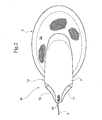
- FIG. 2 is a plane view of the mouse in accordance with the embodiment.
- FIG. 3 is a side view of the mouse in accordance with the embodiment.
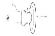
- FIG. 4 is a front view of the mouse in accordance with the embodiment.
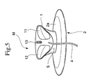
- FIG. 5 is a back view of the mouse in accordance with the embodiment.
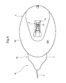
- FIG. 6 is a bottom view of the mouse in accordance with the embodiment.
- FIG. 7 is a longitudinally cross-sectional view showing a state of a hand placing portion in FIG. 4 .
- a mouse M in accordance with the embodiment whose perspective is shown in FIG. 1 , whose plane view is shown FIG. 2 , whose side view is shown in FIG. 3 , whose front view is shown in FIG. 4 , whose back view is shown in FIG. 5 and whose bottom view is shown in FIG. 6 , comprises a body 1 that has buttons 11 , 12 as an input operating portion and a wheel 13 at its front portion, a hand placing portion 2 in a shape of a sheet extending back and forth and right and left from a bottom end portion of the body 1 and a traveling direction detecting portion 3 that scans a traveling direction of the mouse M by the use of an optical means.
- the front here means a direction heading an operator.
- the body 1 is arranged to stand from a general center of the hand placing portion 2 in an elliptical shape of a sheet and a projecting portion 1 a whose shape is tapered toward the forward is arranged to project forward from an upper portion of the body 1 .
- the wheel 13 is arranged at a center of a width direction of the front end portion of the projecting portion 1 a and the buttons 11 , 12 are arranged right and left across the wheel 13 .
- a space S is formed under the projecting portion 1 a having the buttons 11 and 12 to insert a finger.
- the buttons 11 and 12 can be operated with a finger pushed downward or pulled forward.
- the hand placing portion 2 has, as shown in FIG. 6 and FIG. 7 in which a longitudinally cross-sectional view of a part of the hand placing portion 2 shown in FIG. 2 is shown, a soft layer 21 made of a soft material, urethane in this embodiment, and a core layer 22 made of a more rigid material.
- a hand placing face 2 a as an upper face of the core layer 22 and as a face on which a hand is put comprises the soft layer 21 .
- the core layer 22 is arranged under the soft layer 21 .
- An opening 2 x is arranged at a center of a bottom face of the hand placing portion 2 and the traveling direction detecting portion 3 is arranged at the opening 2 x.
- the mouse M can be traveled with keeping the hand put on the hand placing portion 2 . Further, a wrist, an outer portion of a thumb and an outer portion of a pinkie can be placed on the hand placing portion 2 .
- the mouse M can be moved by hanging an index finger and a middle finger on the buttons 11 , 12 respectively and moving the hand horizontally with keeping the wrist placed on the hand placing portion 2 .
- the traveling direction detecting portion 3 comprises, as shown in FIG. 6 , a traveling direction detecting portion body 31 arranged above the opening 2 x of the hand placing portion 2 inside the body 1 and a traveling direction calculating circuit, not shown in drawings, arranged inside the body 1 and detects a traveling direction by the use of the optical means. More specifically, the traveling direction detecting portion body 31 comprises a CMOS image sensor and it detects an image of the top plate, a traveling direction of the mouse M is calculated by the traveling direction calculating circuit and then the traveling direction of the mouse M is sent to the connected information processing unit, not shown in drawings.
- a sliding portion 23 made of a skiddy material, tetrafluoroethylene resin in this embodiment is arranged in a horseshoe shape to surround the opening 2 x under the core layer 22 between the opening 2 x and a peripheral edge of the mouse M.
- a bottom face 23 b of the sliding portion 23 forms a bottom face of the mouse M and the mouse M is used with making the bottom face 23 b of the sliding portion 23 contact with an upper face of the top plate of the desk.
- the hand placing portion 2 is flexible.
- the mouse M can be moved smoothly and the traveling direction detecting portion 3 can be protected from dust because the sliding portion 23 will prevent dust from entering the traveling direction detecting portion 3 .
- the hand placing portion 2 is flexible, it is possible to use the mouse M with keeping a part of the hand floating from the hand placing portion 2 .
- the sliding portion 23 is arranged generally over a frontward and a sideward of the opening 2 x , a generally whole area of the bottom face of the mouse M acts as a lid to cover the traveling direction detecting portion 3 , thereby to protect the traveling direction detecting portion 3 from dust effectively.
- the hand placing portion 2 in a shape of a sheet is arranged under the body 1 and the sliding portion 23 is arranged under the hand placing portion 2 , the sliding portion 23 is pushed against the upper face of the top plate by a weight of the hand if the hand of the operator is put on the hand placing portion 2 , thereby to prevent dust from entering more effectively and further to protect the traveling direction detecting portion 3 against dust effectively.
- the hand placing portion may not be in a shape of a sheet.
- it may be formed in a shape of a plate.
- a dent is arranged on a mouse to place a hand on so that an inner side of the dent constitutes the body and the dent constitutes the hand placing portion.
- the hand placing portion may not be flexible. In this arrangement, it is possible to prevent dust from entering the traveling direction detecting portion as far as the sliding portion is arranged under the hand placing portion.
- the hand placing portion may be omitted. It is possible to prevent dust from entering the traveling direction detecting portion as far as a sliding portion is arranged on the bottom face of the mouse.
- the sliding portion is not necessarily in a shape of the horseshoe. It may be in a shape to surround a circumference of the traveling direction detecting portion or may be arranged generally over the bottom face of the mouse except for the traveling direction detecting portion. In accordance with the arrangement, it is possible to protect the traveling direction detecting portion from dust. Further, if the sliding portion is arranged generally over the bottom face of the mouse except for the traveling direction detecting portion, it is possible to move the mouse smoothly in any state of use.
- the traveling direction detecting portion can be protected from dust as far as the sliding portion is arranged to surround the traveling direction detecting portion.
- the body of the mouse and the input operating portion may not be in the shape of the above-described embodiment, it may be in a semicircle in a side view like a conventional mouse or in other shape.
- sliding portion may be made of a material other than tetrafluoroethylene resin.
- Other component may be variously modified without departing from the spirit of the invention.
Landscapes
- Engineering & Computer Science (AREA)
- General Engineering & Computer Science (AREA)
- Theoretical Computer Science (AREA)
- Human Computer Interaction (AREA)
- Physics & Mathematics (AREA)
- General Physics & Mathematics (AREA)
- Position Input By Displaying (AREA)
Abstract
A mouse M that is used as a pointing device for an information processing unit such as a personal computer comprises a body 1 having at least a button as an input operating portion, a traveling direction detecting portion 3 that detects a direction of traveling by the use of an optical means and a sliding portion 23 made of a skiddy material is arranged to surround the traveling direction detecting portion 3 and is so arranged that the sliding portion 23 forms a bottom face of the mouse M in order to move the mouse M with ease and to protect the traveling direction detecting portion from dust.
Description
- This invention relates to a mouse used as a pointing device for an information processing unit such as a personal computer.
- Conventionally so called an optical mouse used as a pointing device for a personal computer uses a CMOS element or the like as a traveling direction detecting portion and detects a traveling direction by the use of an optical means.
- However, a top plate on which the above-arranged mouse is placed is not always in a dust-free environment. Dust on the top plate attaches to a traveling direction detecting portion of the mouse after a long term use, which deteriorates a quality of an image obtained by the traveling direction detecting portion and hinders the mouse from operating normally.
- In order to solve the above-mentioned problems the present claimed invention is so arranged to prevent dust from attaching around the traveling direction detecting portion.
- A mouse in accordance with the present claimed invention is used as a pointing device for an information processing unit such as a personal computer and comprises a traveling direction detecting portion that detects a traveling direction by the use of an optical means and a sliding portion made of a skiddy material that is arranged to surround the traveling direction detecting portion arranged on a bottom face of the mouse.
- In accordance with the arrangement, the mouse can be moved smoothly due to the sliding portion and the traveling direction detecting portion can be protected from dust because the sliding portion will prevent dust from entering the traveling direction detecting portion.
- In order to protect the traveling direction detecting portion from dust more effectively, the sliding portion may be arranged generally over a frontward and a sideward of the traveling direction detecting portion.
- If the sliding portion is arranged in a horseshoe shape or in a shape to surround the traveling direction detecting portion between the traveling direction detecting portion and a peripheral edge of the bottom face of the mouse, it is possible to protect the traveling direction detecting portion from dust more effectively.
- In order to protect the traveling direction detecting portion from dust further more effectively, the mouse may comprise a body having at least an input operating portion, the traveling direction detecting portion, a hand placing portion that locates at a lower portion of the body and on which a hand of an operator can be put, and the sliding portion arranged at a bottom face of the hand placing portion.
- As an example of a concrete embodiment of the mouse conceived is that the hand placing portion is in a shape of a sheet.
- Further, the sliding portion made of tetrafluoroethylene resin can be conceived as a concrete embodiment of the mouse.
- As mentioned above, since the mouse of the present claimed invention is provided with the sliding portion made of a skiddy material to surround the traveling direction detecting portion, it is possible to move the mouse smoothly and to prevent dust from entering the traveling direction detecting portion through the sliding portion, thereby to protect the traveling direction detecting portion from dust as well.
-
FIG. 1 is a perspective view of a mouse in accordance with one embodiment of the present claimed invention. -
FIG. 2 is a plane view of the mouse in accordance with the embodiment. -
FIG. 3 is a side view of the mouse in accordance with the embodiment. -
FIG. 4 is a front view of the mouse in accordance with the embodiment. -
FIG. 5 is a back view of the mouse in accordance with the embodiment. -
FIG. 6 is a bottom view of the mouse in accordance with the embodiment. -
FIG. 7 is a longitudinally cross-sectional view showing a state of a hand placing portion inFIG. 4 . - An embodiment of the present claimed invention will be described in detail with reference to the accompanying drawings.
- A mouse M in accordance with the embodiment, whose perspective is shown in
FIG. 1 , whose plane view is shownFIG. 2 , whose side view is shown inFIG. 3 , whose front view is shown inFIG. 4 , whose back view is shown inFIG. 5 and whose bottom view is shown inFIG. 6 , comprises abody 1 that hasbuttons wheel 13 at its front portion, ahand placing portion 2 in a shape of a sheet extending back and forth and right and left from a bottom end portion of thebody 1 and a travelingdirection detecting portion 3 that scans a traveling direction of the mouse M by the use of an optical means. The front here means a direction heading an operator. - More concretely, as shown in
FIG. 1 ,FIG. 2 andFIG. 3 , thebody 1 is arranged to stand from a general center of thehand placing portion 2 in an elliptical shape of a sheet and a projectingportion 1 a whose shape is tapered toward the forward is arranged to project forward from an upper portion of thebody 1. As shown inFIG. 1 andFIG. 2 , thewheel 13 is arranged at a center of a width direction of the front end portion of the projectingportion 1 a and thebuttons wheel 13. As shown inFIG. 1 andFIG. 3 , a space S is formed under the projectingportion 1 a having thebuttons buttons - The hand placing
portion 2 has, as shown inFIG. 6 andFIG. 7 in which a longitudinally cross-sectional view of a part of thehand placing portion 2 shown inFIG. 2 is shown, asoft layer 21 made of a soft material, urethane in this embodiment, and acore layer 22 made of a more rigid material. In addition, a hand placingface 2 a as an upper face of thecore layer 22 and as a face on which a hand is put comprises thesoft layer 21. Thecore layer 22 is arranged under thesoft layer 21. An opening 2 x is arranged at a center of a bottom face of thehand placing portion 2 and the travelingdirection detecting portion 3 is arranged at the opening 2 x. - In this embodiment, the mouse M can be traveled with keeping the hand put on the
hand placing portion 2. Further, a wrist, an outer portion of a thumb and an outer portion of a pinkie can be placed on thehand placing portion 2. - Then the mouse M can be moved by hanging an index finger and a middle finger on the
buttons hand placing portion 2. - The traveling
direction detecting portion 3 comprises, as shown inFIG. 6 , a traveling direction detectingportion body 31 arranged above the opening 2 x of thehand placing portion 2 inside thebody 1 and a traveling direction calculating circuit, not shown in drawings, arranged inside thebody 1 and detects a traveling direction by the use of the optical means. More specifically, the traveling direction detectingportion body 31 comprises a CMOS image sensor and it detects an image of the top plate, a traveling direction of the mouse M is calculated by the traveling direction calculating circuit and then the traveling direction of the mouse M is sent to the connected information processing unit, not shown in drawings. - In this embodiment, as shown in
FIG. 6 andFIG. 7 , a slidingportion 23 made of a skiddy material, tetrafluoroethylene resin in this embodiment, is arranged in a horseshoe shape to surround theopening 2 x under thecore layer 22 between the opening 2 x and a peripheral edge of the mouse M. Abottom face 23 b of the slidingportion 23 forms a bottom face of the mouse M and the mouse M is used with making thebottom face 23 b of the slidingportion 23 contact with an upper face of the top plate of the desk. Further, in this embodiment thehand placing portion 2 is flexible. - As mentioned above, since the
bottom face 23 b of the slidingportion 23 forms the bottom face of the mouse M and the slidingportion 23 made of a skiddy material is arranged in the horseshoe shape to surround theopening 2 x, the mouse M can be moved smoothly and the travelingdirection detecting portion 3 can be protected from dust because the slidingportion 23 will prevent dust from entering the travelingdirection detecting portion 3. - In addition, since the
hand placing portion 2 is flexible, it is possible to use the mouse M with keeping a part of the hand floating from thehand placing portion 2. - Especially, since the sliding
portion 23 is arranged generally over a frontward and a sideward of the opening 2 x, a generally whole area of the bottom face of the mouse M acts as a lid to cover the travelingdirection detecting portion 3, thereby to protect the travelingdirection detecting portion 3 from dust effectively. - In addition, since the
hand placing portion 2 in a shape of a sheet is arranged under thebody 1 and the slidingportion 23 is arranged under thehand placing portion 2, the slidingportion 23 is pushed against the upper face of the top plate by a weight of the hand if the hand of the operator is put on thehand placing portion 2, thereby to prevent dust from entering more effectively and further to protect the travelingdirection detecting portion 3 against dust effectively. - The present claimed invention is not limited to the above-described embodiments.
- For example, the hand placing portion may not be in a shape of a sheet. For example, it may be formed in a shape of a plate. Or a dent is arranged on a mouse to place a hand on so that an inner side of the dent constitutes the body and the dent constitutes the hand placing portion. Further, the hand placing portion may not be flexible. In this arrangement, it is possible to prevent dust from entering the traveling direction detecting portion as far as the sliding portion is arranged under the hand placing portion.
- In addition, the hand placing portion may be omitted. It is possible to prevent dust from entering the traveling direction detecting portion as far as a sliding portion is arranged on the bottom face of the mouse.
- Further, the sliding portion is not necessarily in a shape of the horseshoe. It may be in a shape to surround a circumference of the traveling direction detecting portion or may be arranged generally over the bottom face of the mouse except for the traveling direction detecting portion. In accordance with the arrangement, it is possible to protect the traveling direction detecting portion from dust. Further, if the sliding portion is arranged generally over the bottom face of the mouse except for the traveling direction detecting portion, it is possible to move the mouse smoothly in any state of use.
- Even though the sliding portion is not arranged generally over the whole area of the bottom face of the mouse, the traveling direction detecting portion can be protected from dust as far as the sliding portion is arranged to surround the traveling direction detecting portion.
- In addition, the body of the mouse and the input operating portion may not be in the shape of the above-described embodiment, it may be in a semicircle in a side view like a conventional mouse or in other shape.
- Further, the sliding portion may be made of a material other than tetrafluoroethylene resin. Other component may be variously modified without departing from the spirit of the invention.
Claims (14)
1. A mouse that is used as a pointing device for an information processing unit such as a personal computer and characterized by comprising a body having at least an input operating portion and a traveling direction detecting portion that detects a direction of traveling by the use of an optical means and a sliding portion made of a skiddy material is arranged to surround the traveling direction detecting portion wherein the sliding portion forms a bottom face of the mouse.
2. The mouse described in claim 1 and characterized by that the sliding portion is arranged generally over at least a frontward and a sideward of the traveling direction detecting portion.
3. The mouse described in claim 1 , and characterized by that the sliding portion is arranged in a horseshoe shape or in a shape to surround the traveling direction detecting portion between the traveling direction detecting portion and a peripheral edge of the bottom face of the mouse.
4. The mouse described in claim 1 , and characterized by that further comprising a hand placing portion on which a hand of an operator can be put and the sliding portion is arranged at a bottom face of the hand placing portion.
5. The mouse described in claim 4 , and characterized by that the hand placing portion is in a shape of a sheet.
6. The mouse described in claim 1 , and characterized by that the sliding portion is made of tetrafluoroethylene resin.
7. The mouse described in claim 2 , and characterized by that further comprising a hand placing portion on which a hand of an operator can be put and the sliding portion is arranged at a bottom face of the hand placing portion.
8. The mouse described in claim 7 , and characterized by that the hand placing portion is in a shape of a sheet.
9. The mouse described in claim 2 , and characterized by that the sliding portion is made of tetrafluoroethylene resin.
10. The mouse described in claim 3 , and characterized by that further comprising a hand placing portion on which a hand of an operator can be put and the sliding portion is arranged at a bottom face of the hand placing portion.
11. The mouse described in claim 10 , and characterized by that the hand placing portion is in a shape of a sheet.
12. The mouse described in claim 3 , and characterized by that the sliding portion is made of tetrafluoroethylene resin.
13. The mouse described in claim 4 , and characterized by that the sliding portion is made of tetrafluoroethylene resin.
14. The mouse described in claim 5 , and characterized by that the sliding portion is made of tetrafluoroethylene resin.
Priority Applications (3)
| Application Number | Priority Date | Filing Date | Title |
|---|---|---|---|
| JP2002162212A JP2004029865A (en) | 2002-06-03 | 2002-06-03 | Mouse |
| US10/651,084 US20050057504A1 (en) | 2002-06-03 | 2003-08-29 | Mouse |
| US10/651,086 US20040196263A1 (en) | 2002-06-03 | 2003-08-29 | Mouse |
Applications Claiming Priority (2)
| Application Number | Priority Date | Filing Date | Title |
|---|---|---|---|
| JP2002162212A JP2004029865A (en) | 2002-06-03 | 2002-06-03 | Mouse |
| US10/651,084 US20050057504A1 (en) | 2002-06-03 | 2003-08-29 | Mouse |
Publications (1)
| Publication Number | Publication Date |
|---|---|
| US20050057504A1 true US20050057504A1 (en) | 2005-03-17 |
Family
ID=34554076
Family Applications (2)
| Application Number | Title | Priority Date | Filing Date |
|---|---|---|---|
| US10/651,084 Abandoned US20050057504A1 (en) | 2002-06-03 | 2003-08-29 | Mouse |
| US10/651,086 Abandoned US20040196263A1 (en) | 2002-06-03 | 2003-08-29 | Mouse |
Family Applications After (1)
| Application Number | Title | Priority Date | Filing Date |
|---|---|---|---|
| US10/651,086 Abandoned US20040196263A1 (en) | 2002-06-03 | 2003-08-29 | Mouse |
Country Status (2)
| Country | Link |
|---|---|
| US (2) | US20050057504A1 (en) |
| JP (1) | JP2004029865A (en) |
Cited By (3)
| Publication number | Priority date | Publication date | Assignee | Title |
|---|---|---|---|---|
| US20040196263A1 (en) * | 2002-06-03 | 2004-10-07 | Kokuyo Co., Ltd. | Mouse |
| US20080238876A1 (en) * | 2004-03-22 | 2008-10-02 | Avago Technologies Ecbu Ip (Singapore) Pte. Ltd. | Contaminant-resistant optical mouse and cradle |
| US20110012834A1 (en) * | 2008-01-22 | 2011-01-20 | Yong Guo | Human body engineerin mouse |
Families Citing this family (2)
| Publication number | Priority date | Publication date | Assignee | Title |
|---|---|---|---|---|
| KR101090424B1 (en) | 2004-09-22 | 2011-12-06 | 김석진 | Computer mouse |
| KR200460441Y1 (en) * | 2011-12-16 | 2012-05-25 | 최은석 | Computer mouse |
Citations (2)
| Publication number | Priority date | Publication date | Assignee | Title |
|---|---|---|---|---|
| US20030142078A1 (en) * | 2002-01-29 | 2003-07-31 | Unity Opto Technology Co. Ltd. | Optical mouse for a personal computer |
| US20040196263A1 (en) * | 2002-06-03 | 2004-10-07 | Kokuyo Co., Ltd. | Mouse |
Family Cites Families (5)
| Publication number | Priority date | Publication date | Assignee | Title |
|---|---|---|---|---|
| US5355146A (en) * | 1990-03-05 | 1994-10-11 | Bmc Micro-Industries Ltd. | Multi-directional hand scanner and mouse |
| US5894303A (en) * | 1995-03-14 | 1999-04-13 | Barr; Ann E. | Computer mouse and shell therefore |
| US6390423B1 (en) * | 1998-12-04 | 2002-05-21 | Fellowes, Inc. | Ergonomic soft-feel mouse |
| US6954198B2 (en) * | 2002-05-02 | 2005-10-11 | Hung-Ying Shih | Ergonomically shaped computer pointing device |
| US20030234765A1 (en) * | 2002-06-25 | 2003-12-25 | Simon Suh | Vertical handheld computer mouse |
-
2002
- 2002-06-03 JP JP2002162212A patent/JP2004029865A/en active Pending
-
2003
- 2003-08-29 US US10/651,084 patent/US20050057504A1/en not_active Abandoned
- 2003-08-29 US US10/651,086 patent/US20040196263A1/en not_active Abandoned
Patent Citations (2)
| Publication number | Priority date | Publication date | Assignee | Title |
|---|---|---|---|---|
| US20030142078A1 (en) * | 2002-01-29 | 2003-07-31 | Unity Opto Technology Co. Ltd. | Optical mouse for a personal computer |
| US20040196263A1 (en) * | 2002-06-03 | 2004-10-07 | Kokuyo Co., Ltd. | Mouse |
Cited By (4)
| Publication number | Priority date | Publication date | Assignee | Title |
|---|---|---|---|---|
| US20040196263A1 (en) * | 2002-06-03 | 2004-10-07 | Kokuyo Co., Ltd. | Mouse |
| US20080238876A1 (en) * | 2004-03-22 | 2008-10-02 | Avago Technologies Ecbu Ip (Singapore) Pte. Ltd. | Contaminant-resistant optical mouse and cradle |
| US8730168B2 (en) * | 2004-03-22 | 2014-05-20 | Pixart Imaging Inc. | Contaminant-resistant optical mouse and cradle |
| US20110012834A1 (en) * | 2008-01-22 | 2011-01-20 | Yong Guo | Human body engineerin mouse |
Also Published As
| Publication number | Publication date |
|---|---|
| JP2004029865A (en) | 2004-01-29 |
| US20040196263A1 (en) | 2004-10-07 |
Similar Documents
| Publication | Publication Date | Title |
|---|---|---|
| US8014148B2 (en) | Electronic device | |
| US7777723B2 (en) | Mouse | |
| US6646866B2 (en) | Protective case for a tablet personal computer | |
| US8564938B2 (en) | Electronic apparatus | |
| EP1191424A3 (en) | Information processing apparatus | |
| US20160014308A1 (en) | Palm vein imaging apparatus | |
| US20050116933A1 (en) | Dual mode computer mouse | |
| US7298362B2 (en) | Pointing device with finger-contact control | |
| US6887002B1 (en) | Keyboard cover | |
| JP2009230753A (en) | Electronic device | |
| US20190007084A1 (en) | Protective/control receptacle | |
| US20050057504A1 (en) | Mouse | |
| US10242812B2 (en) | Electric appliance | |
| WO2002054215A1 (en) | A portable device for inputting control signals to a peripheral unit, and use of such a device | |
| US20080237013A1 (en) | Electronic equipment | |
| US7764270B2 (en) | Computer mouse | |
| US7016185B2 (en) | Decorative/ergonomic cover or sheath for computer peripherals and other electronic devices | |
| CN203133781U (en) | Hand pad for touch screen of electronic device | |
| JP2001236177A (en) | Mouse | |
| US20210091452A1 (en) | Electronic device | |
| TWI289777B (en) | Mouse | |
| US20050057505A1 (en) | Mouse | |
| CN1591301A (en) | Mouse | |
| KR200217005Y1 (en) | a pad unit for handling a mouse | |
| US20250138656A1 (en) | Mouse and Replacement Support Kit |
Legal Events
| Date | Code | Title | Description |
|---|---|---|---|
| AS | Assignment |
Owner name: KOKUYO CO., LTD., JAPAN Free format text: ASSIGNMENT OF ASSIGNORS INTEREST;ASSIGNORS:AKIYAMA, HIROAKI;WATANABE, TSUYOSHI;NAKAGAWA, SATOSHI;REEL/FRAME:015464/0196;SIGNING DATES FROM 20031009 TO 20031030 |
|
| STCB | Information on status: application discontinuation |
Free format text: ABANDONED -- FAILURE TO RESPOND TO AN OFFICE ACTION |