US20050012481A1 - Method and apparatus for processing the output signal of an encoder - Google Patents
Method and apparatus for processing the output signal of an encoder Download PDFInfo
- Publication number
- US20050012481A1 US20050012481A1 US10/892,204 US89220404A US2005012481A1 US 20050012481 A1 US20050012481 A1 US 20050012481A1 US 89220404 A US89220404 A US 89220404A US 2005012481 A1 US2005012481 A1 US 2005012481A1
- Authority
- US
- United States
- Prior art keywords
- multiplied
- frequency
- sinusoidal
- signal
- signals
- Prior art date
- Legal status (The legal status is an assumption and is not a legal conclusion. Google has not performed a legal analysis and makes no representation as to the accuracy of the status listed.)
- Granted
Links
Images
Classifications
-
- H—ELECTRICITY
- H03—ELECTRONIC CIRCUITRY
- H03M—CODING; DECODING; CODE CONVERSION IN GENERAL
- H03M1/00—Analogue/digital conversion; Digital/analogue conversion
- H03M1/12—Analogue/digital converters
-
- G—PHYSICS
- G01—MEASURING; TESTING
- G01D—MEASURING NOT SPECIALLY ADAPTED FOR A SPECIFIC VARIABLE; ARRANGEMENTS FOR MEASURING TWO OR MORE VARIABLES NOT COVERED IN A SINGLE OTHER SUBCLASS; TARIFF METERING APPARATUS; MEASURING OR TESTING NOT OTHERWISE PROVIDED FOR
- G01D5/00—Mechanical means for transferring the output of a sensing member; Means for converting the output of a sensing member to another variable where the form or nature of the sensing member does not constrain the means for converting; Transducers not specially adapted for a specific variable
- G01D5/12—Mechanical means for transferring the output of a sensing member; Means for converting the output of a sensing member to another variable where the form or nature of the sensing member does not constrain the means for converting; Transducers not specially adapted for a specific variable using electric or magnetic means
- G01D5/244—Mechanical means for transferring the output of a sensing member; Means for converting the output of a sensing member to another variable where the form or nature of the sensing member does not constrain the means for converting; Transducers not specially adapted for a specific variable using electric or magnetic means influencing characteristics of pulses or pulse trains; generating pulses or pulse trains
- G01D5/24404—Interpolation using high frequency signals
-
- B—PERFORMING OPERATIONS; TRANSPORTING
- B41—PRINTING; LINING MACHINES; TYPEWRITERS; STAMPS
- B41J—TYPEWRITERS; SELECTIVE PRINTING MECHANISMS, i.e. MECHANISMS PRINTING OTHERWISE THAN FROM A FORME; CORRECTION OF TYPOGRAPHICAL ERRORS
- B41J19/00—Character- or line-spacing mechanisms
- B41J19/18—Character-spacing or back-spacing mechanisms; Carriage return or release devices therefor
- B41J19/20—Positive-feed character-spacing mechanisms
- B41J19/202—Drive control means for carriage movement
Definitions
- the invention relates to a motor control, and more particularly, to a signal processing method and apparatus for improving the speed and the position resolutions of an encoder output signal when the motor control is performed using an analog output encoder.
- a recording medium is carried therein using at least one feed roll along a carry path.
- the recording medium To form an image accurately on the recording medium, the recording medium must be placed at a specific location.
- the feed roll To position the recording medium at the specific location, the feed roll must move with high precision. Hence, the quality of an image is often very dependent upon precise control of the position of the feed roll.
- An encoder is typically used to precisely control the position of a feed roll.
- An encoder typically uses at least one sensor to sense slits that are position marks and formed along the track of a code wheel, for example, a disk.
- the code wheel has a central shaft in alignment with the central shaft of a feed roll and rotates with a rotation of the feed roll.
- the code wheel rotates, the number of slits by which the sensor and its accompanying elements pass is counted. Since each of the slits indicates movement of the code wheel at a predetermined angle, changes in the position of the recording medium carried by the feed roll can be tracked.
- a square-wave pulse encoder cannot obtain distinct position information between rising and falling edges of a square-wave pulse output by the encoder.
- an analog output encoder is used because fine position information can be obtained even during one cycle by finely dividing the angles of rotation of a motor by analog values.
- a code wheel is enlarged, or the interval between adjacent slits is reduced.
- the analog output encoder becomes large and bulky. If the interval between adjacent slits is reduced, an encoder output signal is highly likely to be unstabilized due to the characteristics of the electrical circuit of a sensor, the sensitivity of the sensor, and the mechanical and optical characteristics of the code wheel.
- a signal processing circuit in which a sinusoidal signal output by the analog output encoder is divided into 2 n sections according to the resolution of analog-to-digital conversion, that is, according to the number of bits, n, and an instantaneous value is read out from each of the 2 n sections so that analog-to-digital conversion is performed.
- this method numerical errors and jitters often occur on the curve of the sinusoidal signal due to the characteristics of the sinusoidal signal in that only about ⁇ /4 of a half-period maintains linearity, and, accordingly, a processor using an analog-to-digital converted signal cannot precisely control the location or speed of a recording medium. Also, because the sections sequentially undergo the analog-to-digital conversion, delay time is generated, and a load on the processor increases. Such problems adversely affect other signal processing operations performed in the processor.
- One aspect of the invention provides a method of and an apparatus for processing a signal output by an encoder, in which sinusoidal signals having different phases, which are output by the encoder, are frequency-multiplied, and the frequency-multiplied sinusoidal signals are converted into square-wave signals, and a position controlling system which adopts the signal processing apparatus and method so as to precisely control the position or speed of a to-be-controlled object.
- a method of processing a signal output by an encoder includes: repeatedly performing an operation n times (where n is an integer equal to or greater than 1), by which each of frequencies of a pair of first and second sinusoidal signals is multiplied by 2, wherein the first and second sinusoidal signals are provided by the encoder and the second sinusoidal signal is substantially 90 degrees out of phase with the first sinusoidal signal; selecting one pair of n pairs of frequency-multiplied sinusoidal signals in response to a control signal and converting the selected frequency-multiplied sinusoidal signal pair into square wave signals.
- an apparatus for processing a signal output by an encoder including a frequency multiplication unit repeatedly performing an operation n times (where n is an integer equal to or greater than 1), by which each of frequencies of a pair of first and second sinusoidal signals is multiplied by 2, wherein the first and second sinusoidal signals are provided by the encoder and the second sinusoidal signal is substantially 90 degrees out of phase with the first sinusoidal signal; and an analog-to-digital converter converting each of n pairs of frequency-multiplied sinusoidal signals obtained by the frequency multiplication unit into square wave signals
- a position or speed controlling system including: a frequency multiplication unit repeatedly performing an operation n times (where n is an integer equal to or greater than 1), by which each of frequencies of a pair of first and second sinusoidal signals is multiplied by 2, wherein the first and second sinusoidal signals are provided by the encoder and the second sinusoidal signal is substantially 90 degrees out of phase with the first sinusoidal signal; an analog-to-digital converter selecting one pair of the n pairs of frequency-multiplied sinusoidal signals obtained by the frequency multiplication unit in response to a control signal and converting the selected frequency-multiplied sinusoidal signal pair into square wave signals; and a controller controlling the position or speed of a to-be-controlled object by counting pulses of square wave signals provided by the analog-to-digital converter.
- FIGS. 1A and 1B are perspective views of an encoder to which the invention is applied;
- FIG. 2 is a block diagram of a structure of an apparatus for processing a signal output by an encoder, according to an aspect of the invention
- FIG. 3 is a block diagram of a structure of the frequency multiplier of FIG. 2 ;
- FIG. 4 is a block diagram of a structure of the analog-to-digital converter of FIG. 2 ;
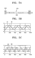
- FIGS. 5A through 5D show waveforms of outputs of the portions shown in FIGS. 2 through 4 ;
- FIG. 6 is a block diagram of a structure of an apparatus for processing a signal output by an encoder, according to another second aspect of the invention.
- FIG. 7 is a flowchart illustrating a method of processing a signal output by an encoder, according to an aspect of the invention.
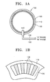
- FIG. 1A is a perspective view showing major elements of an encoder 100 to which the invention has been applied.
- Various types of encoders can be used as the encoder 100 , such as a rotary encoder used to detect the rotation angle of a disk attached to a rotating shaft for carrying a print medium of a printer, or a linear encoder used to detect the moving distance of a print head that moves linearly.
- slits 130 are formed on a track 120 at regular intervals in a radial shape.
- the track 120 is installed on the outer circumference of a disk 110 connected to a rotation shaft of a motor (not shown).
- a light emitting diode (not shown) is disposed at one side of the slits 130 , and a plurality of light receiving diode (not shown) are disposed at the other side of the slits 130 .
- the light emitting diode and the light receiving diodes form a sensor 140 . Light from the light emitting diode passes through the slits 130 and falls upon the light receiving diodes.
- the sensor 140 changes the sinusoidal current to a voltage and generates an A phase sinusoidal signal 150 and a B phase sinusoidal signal 160 , wherein the B phase sinusoidal signal is approximately 90 degrees out of phase with the A phase sinusoidal signal 150 .
- FIG. 1B is a partially magnified view of the disk 110 of FIG. 1A .
- the track 120 includes the plurality of slits 130 arranged at regular intervals.
- Each of the slits 130 for example, is mostly translucent and has substantially a trapezoid shape.
- the sensor 140 discerns the slits 130 by producing an output corresponding to the amount of light transmitted by the translucent slits 130 . If the number of slits 130 arranged on one track is M, the period of each of the A and B phase sinusoidal signals 150 and 160 is 1/M.
- the shape of the slits is not limited to the substantially trapezoidal shape.
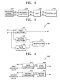
- FIG. 2 is a block diagram of a structure of an apparatus for processing a signal output by an encoder, according to a first aspect of the invention.
- this apparatus includes an encoder signal receiver 210 , a frequency multiplier 220 , an analog-to-digital converter (ADC) 230 , and a controller 240 .
- ADC analog-to-digital converter
- the encoder signal receiver 210 receives an A phase sinusoidal signal A 1 and a B phase sinusoidal signal B 1 from the encoder 100 of FIG. 1 .
- the frequency multiplier 220 receives the A-phase and B-phase sinusoidal signals A 1 and B 1 from the encoder signal receiver 210 and multiplies the frequency of each of them by a predetermined integer to generate sinusoidal signals A 2 and B 2 .
- the predetermined number used to generate sinusoidal signals A 2 and B 2 is 2.
- the ADC 230 receives the sinusoidal signals A 2 and B 2 from the frequency multiplier 220 and performs an analog-to-digital conversion on each sinusoidal signal to generate square wave signals A 3 and B 3 .
- the controller 240 receives the square wave signals A 3 and B 3 from the ADC 230 , counts the number of rising and/or falling edges, that is, pulses of the square wave signals A 3 and B 3 , to determine the current position or speed of a to-be-controlled object, and feeds the determined position or speed value back to the encoder 100 .
- the frequency multiplier 220 , the ADC 230 , and the controller 240 may be integrated as one chip using an Application Specific Integrated Circuit (ASIC).
- ASIC Application Specific Integrated Circuit
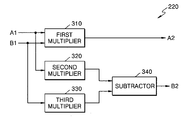
- FIG. 3 is a block diagram of a structure of the frequency multiplier 220 of FIG. 2 .
- the frequency multiplier 220 includes first, second, and third multipliers 310 , 320 , and 330 and a subtractor 340 .
- the invention may include more or less than three multipliers and one subtractor.
- the A phase sinusoidal signal A 1 can be expressed as sin ( ⁇ )
- the B phase sinusoidal signal B 1 can be expressed as sin ( ⁇ /2), that is, ⁇ cos ( ⁇ ).
- the first multiplier 310 multiplies the frequencies of the A-phase and B-phase sinusoidal signals A 1 and B 1 shown in FIG. 5B and received from the encoder signal receiver 210 by a predetermined valve, for example, 2 to generate the sinusoidal signal A 2 shown in FIG. 5C and defined as in Equation 1:
- the second multiplier 320 multiplies the frequency of the A-phase sinusoidal signal A 1 shown in FIG. 5B and received from the encoder signal receiver 210 by itself and provides the product of sin ( ⁇ ) 2 to the subtractor 340 .
- the third multiplier 330 multiplies the frequency of the B-phase sinusoidal signal B 1 shown in FIG. 5B and received from the encoder signal receiver 210 by itself and provides the product of cos ( ⁇ ) 2 to the subtractor 340 .
- the sinusoidal signals A 2 and B 2 output by the first multiplier 310 and the subtractor 340 , respectively, have half of the periods of and the same amplitudes as the sinusoidal signals A 1 and B 1 received from the encoder signal receiver 210 .
- the sinusoidal signals A 2 and B 2 have frequencies that are double the frequencies of the sinusoidal signals A 1 and B 1 .
- FIG. 4 is a block diagram of a structure of the ADC 230 of FIG. 2 , including first and second comparators 410 and 420 and first and second filters 430 and 440 .
- the first comparator 410 compares the amplitude of the sinusoidal signal A 2 received from the frequency multiplier 220 with a first reference value (e.g., 0), which is a value half way between the maximum amplitude (e.g., +1) and minimum amplitude (e.g., ⁇ 1) of the sinusoidal signal A 2 in order to produce, for example, a digital signal with a duty of 50%.
- a first reference value e.g., 0
- the first comparator 410 outputs a “+1” signal when the sinusoidal signal A 2 is greater than the first reference value, and a “ ⁇ 1” signal when the sinusoidal signal A 2 is smaller than the first reference value, thereby generating the square wave signal A 3 , as shown in FIG. 5D .
- the second comparator 420 compares the sinusoidal signal B 2 received from the frequency multiplier 220 with a second reference value (e.g., 0), which is a value half way between the maximum amplitude (e.g., +1) and minimum amplitude (e.g., ⁇ 1) of the sinusoidal signal B 2 in order to produce, for example, a digital signal with a duty of 50%.
- the second comparator 420 outputs a “+1” signal when the sinusoidal signal B 2 is greater than the second reference value, and a “ ⁇ 1” signal when the sinusoidal signal B 2 is smaller than the second reference value, thereby generating the square wave signal B 3 as shown in FIG. 5D .
- the first filter 430 receives the square wave signal A 3 from the first comparator 410 and filters the same to remove an unnecessary signal, such as noise, included in it.
- the second filter 440 receives the square wave signal B 3 from the second comparator 420 and filters the same to remove an unnecessary signal, such as, noise, included in it.
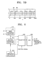
- FIG. 6 is a block diagram of a structure of an apparatus for processing a signal output by an encoder, according to a second aspect of the invention.
- the signal processing apparatus includes a frequency multiplication unit 610 , a selector 620 , and an ADC 630 .
- the frequency multiplication portion 610 includes first through n-th frequency multipliers 611 , 612 , and 613 .
- the n-th frequency multiplier 613 receives 2(n ⁇ 1) frequency-multiplied sinusoidal signals from an (n ⁇ 1)th frequency multiplier (not shown), again multiplies frequencies thereof by 2, and outputs the 2 n frequency-multiplied sinusoidal signals to the selector 620 .
- the frequency multiplication unit 610 outputs sinusoidal signals obtained by multiplying frequencies of the sinusoidal signals A 1 and B 1 by 2 1 through 2 n (where n is an integer equal to or greater than 1).
- the selector 620 selects one pair of the frequency-multiplied sinusoidal signals received from the frequency multiplication unit 610 in response to a control signal and provides the selected sinusoidal signal pair to the ADC 630 .
- the control signal is produced in various ways. If the control signal includes k bits, one pair can be selected from 2 k pairs of frequency-multiplied sinusoidal signals obtained by the frequency multiplication unit 610 . At this time, one pair of sinusoidal signals may be selected among the 2 k pairs of frequency-multiplied sinusoidal signals obtained by the frequency multiplication unit 610 , in proportion with precise control of the location or speed of an object to-be-controlled using the output signal of the encoder 100 .
- the ADC 630 has the same structure as the ADC 230 shown in FIG. 4 .
- the ADC 630 converts the sinusoidal signals selected by the selector 620 into square wave signals and filters the square wave signals to remove noise or unnecessary signals contained in it.
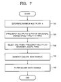
- FIG. 7 is a flowchart illustrating a method of processing a signal output by an encoder, according to an aspect of the invention.
- a maximum multiplier, 2 n (where n is an integer equal to or greater than 1), for a pair of sinusoidal signals A 1 and B 1 provided by the encoder 100 is determined according to the precision of control of the location and/or speed of an object to be controlled using the output signal of the encoder 100 .
- an operation by which each of frequencies of the two sinusoidal signals A 1 and B 1 is multiplied by a predetermined integer, such as 2, is repeatedly performed n times, on the basis of the maximum multiplier, 2 n , for the sinusoidal signals A 1 and B 1 .
- one pair is selected from n pairs of sinusoidal signals, that is, 2 1 through 2 n frequency-multiplied sinusoidal signals obtained by multiplying frequencies of the sinusoidal signals A 1 and B 1 by 2 1 through 2 n .
- the selected frequency-multiplied sinusoidal signals are converted into square wave signals.
- the square wave signals are filtered and provided to the controller 240 of FIG. 2 .
- the encoder signal processing method according to the invention does not include operation 730 , an operation by which each of frequencies of the two sinusoidal signals A 1 and B 1 is multiplied by a predetermined integer, such as 2, is repeatedly performed n times, on the basis of the determined maximum multiplier, n. Thereafter, in operations 740 and 750 , final 2 n frequency-multiplied sinusoidal signals are converted into square wave signals, and the square wave signals are filtered.
- a process in which an operation by which each of frequencies of the sinusoidal signals A 1 and B 1 are multiplied by 2 is repeatedly performed n times, and final 2 n frequency-multiplied sinusoidal signals are converted into square wave signals according to the invention corresponds to a general n-bit analog-to-digital conversion.
- an 8-bit analog-to-digital conversion corresponds to a process in which 2 8 frequency-multiplied sinusoidal signals are converted into square wave signals according to the invention, but the process according to the invention provides a much higher precision, i.e., resolution.
- the invention can be embodied as computer readable codes on a computer readable recording medium to be read by a computer.
- the computer readable recording medium is any data storage device that can store data that can be thereafter read by a computer system. Examples of the computer readable recording medium include read-only memory (ROM), random-access memory (RAM), CD-ROMs, magnetic tapes, floppy disks, optical data storage devices, and so on.
- the computer readable codes can be transmitted via a carrier wave such as Internet.
- the computer readable recording medium can also be distributed over network coupled computer systems so that the computer readable code is stored and executed in a distributed fashion. Functional programs, codes, and code segments for accomplishing the invention can be easily construed by programmers in the technical field to which the invention pertains.
- the square wave signals are applied to a controller for controlling the location or speed of a to-be-controlled object by using an output signal of the encoder.
- the encoder signal processing method and apparatus according to the invention can be applied to various types of encoders, such as, a rotary encoder used to detect the rotation angle of a disk attached to a rotating shaft for carrying a print medium of a printer, or a linear encoder used to detect the moving distance of a print head that moves linearly.
- a rotary encoder used to detect the rotation angle of a disk attached to a rotating shaft for carrying a print medium of a printer
- a linear encoder used to detect the moving distance of a print head that moves linearly.
- the physical resolution of the encoder can be improved without increasing the number of slits arranged on the disk.
- the encoder signal processing method and apparatus according to the invention can be applied to various types of systems for controlling the location or speed of a to-be-controlled object by using an output signal of the encoder.
- the physical resolution of the encoder can be improved without increasing the number of slits arranged on the disk.
- the number of slits arranged on the disk can be reduced according to the invention, it is possible to reduce the radius of the disk of the encoder.
- the overall size of the encoder can be reduced, thereby reducing the costs for manufacturing the encoder.
Abstract
Description
- This application claims the priority of Korean Patent Application No. 2003-48648, filed on Jul. 16, 2003, in the Korean Intellectual Property Office, the disclosure of which is incorporated herein in its entirety by reference.
- 1. Field of the Invention
- The invention relates to a motor control, and more particularly, to a signal processing method and apparatus for improving the speed and the position resolutions of an encoder output signal when the motor control is performed using an analog output encoder.
- 2. Description of the Related Art
- In conventional ink jet imaging apparatuses, a recording medium is carried therein using at least one feed roll along a carry path. To form an image accurately on the recording medium, the recording medium must be placed at a specific location. To position the recording medium at the specific location, the feed roll must move with high precision. Hence, the quality of an image is often very dependent upon precise control of the position of the feed roll. An encoder is typically used to precisely control the position of a feed roll.
- An encoder typically uses at least one sensor to sense slits that are position marks and formed along the track of a code wheel, for example, a disk. Preferably, the code wheel has a central shaft in alignment with the central shaft of a feed roll and rotates with a rotation of the feed roll. When the code wheel rotates, the number of slits by which the sensor and its accompanying elements pass is counted. Since each of the slits indicates movement of the code wheel at a predetermined angle, changes in the position of the recording medium carried by the feed roll can be tracked.
- A square-wave pulse encoder cannot obtain distinct position information between rising and falling edges of a square-wave pulse output by the encoder. Hence, an analog output encoder is used because fine position information can be obtained even during one cycle by finely dividing the angles of rotation of a motor by analog values. To increase a resolution of an analog output encoder, a code wheel is enlarged, or the interval between adjacent slits is reduced. However, if the code wheel is enlarged, the analog output encoder becomes large and bulky. If the interval between adjacent slits is reduced, an encoder output signal is highly likely to be unstabilized due to the characteristics of the electrical circuit of a sensor, the sensitivity of the sensor, and the mechanical and optical characteristics of the code wheel.
- Also, to increase the resolution of an analog output encoder, a signal processing circuit is used, in which a sinusoidal signal output by the analog output encoder is divided into 2n sections according to the resolution of analog-to-digital conversion, that is, according to the number of bits, n, and an instantaneous value is read out from each of the 2n sections so that analog-to-digital conversion is performed. However, in this method, numerical errors and jitters often occur on the curve of the sinusoidal signal due to the characteristics of the sinusoidal signal in that only about π/4 of a half-period maintains linearity, and, accordingly, a processor using an analog-to-digital converted signal cannot precisely control the location or speed of a recording medium. Also, because the sections sequentially undergo the analog-to-digital conversion, delay time is generated, and a load on the processor increases. Such problems adversely affect other signal processing operations performed in the processor.
- One aspect of the invention provides a method of and an apparatus for processing a signal output by an encoder, in which sinusoidal signals having different phases, which are output by the encoder, are frequency-multiplied, and the frequency-multiplied sinusoidal signals are converted into square-wave signals, and a position controlling system which adopts the signal processing apparatus and method so as to precisely control the position or speed of a to-be-controlled object.
- According to an aspect of the invention, there is provided a method of processing a signal output by an encoder, includes: repeatedly performing an operation n times (where n is an integer equal to or greater than 1), by which each of frequencies of a pair of first and second sinusoidal signals is multiplied by 2, wherein the first and second sinusoidal signals are provided by the encoder and the second sinusoidal signal is substantially 90 degrees out of phase with the first sinusoidal signal; selecting one pair of n pairs of frequency-multiplied sinusoidal signals in response to a control signal and converting the selected frequency-multiplied sinusoidal signal pair into square wave signals.
- According to another aspect of the invention, there is provided an apparatus for processing a signal output by an encoder, including a frequency multiplication unit repeatedly performing an operation n times (where n is an integer equal to or greater than 1), by which each of frequencies of a pair of first and second sinusoidal signals is multiplied by 2, wherein the first and second sinusoidal signals are provided by the encoder and the second sinusoidal signal is substantially 90 degrees out of phase with the first sinusoidal signal; and an analog-to-digital converter converting each of n pairs of frequency-multiplied sinusoidal signals obtained by the frequency multiplication unit into square wave signals
- According to an aspect of the invention, there is provided a position or speed controlling system including: a frequency multiplication unit repeatedly performing an operation n times (where n is an integer equal to or greater than 1), by which each of frequencies of a pair of first and second sinusoidal signals is multiplied by 2, wherein the first and second sinusoidal signals are provided by the encoder and the second sinusoidal signal is substantially 90 degrees out of phase with the first sinusoidal signal; an analog-to-digital converter selecting one pair of the n pairs of frequency-multiplied sinusoidal signals obtained by the frequency multiplication unit in response to a control signal and converting the selected frequency-multiplied sinusoidal signal pair into square wave signals; and a controller controlling the position or speed of a to-be-controlled object by counting pulses of square wave signals provided by the analog-to-digital converter.
- Additional aspects and/or advantages of the invention will be set forth in part in the description which follows and, in part, will be obvious from the description, or may be learned by practice of the invention.
- These and/or other aspects and advantages of the invention will become apparent and more readily appreciated from the following description of the embodiments, taken in conjunction with the accompanying drawings of which:
-
FIGS. 1A and 1B are perspective views of an encoder to which the invention is applied; -
FIG. 2 is a block diagram of a structure of an apparatus for processing a signal output by an encoder, according to an aspect of the invention; -
FIG. 3 is a block diagram of a structure of the frequency multiplier ofFIG. 2 ; -
FIG. 4 is a block diagram of a structure of the analog-to-digital converter ofFIG. 2 ; -
FIGS. 5A through 5D show waveforms of outputs of the portions shown inFIGS. 2 through 4 ; -
FIG. 6 is a block diagram of a structure of an apparatus for processing a signal output by an encoder, according to another second aspect of the invention; and -
FIG. 7 is a flowchart illustrating a method of processing a signal output by an encoder, according to an aspect of the invention. - Reference will now be made in detail to the embodiments of the invention, examples of which are illustrated in the accompanying drawings, wherein like reference numerals refer to the like elements throughout. The embodiments are described below to explain the invention by referring to the figures.
-
FIG. 1A is a perspective view showing major elements of anencoder 100 to which the invention has been applied. Various types of encoders can be used as theencoder 100, such as a rotary encoder used to detect the rotation angle of a disk attached to a rotating shaft for carrying a print medium of a printer, or a linear encoder used to detect the moving distance of a print head that moves linearly. - Referring to
FIG. 1A ,slits 130 are formed on atrack 120 at regular intervals in a radial shape. Thetrack 120 is installed on the outer circumference of adisk 110 connected to a rotation shaft of a motor (not shown). A light emitting diode (not shown) is disposed at one side of theslits 130, and a plurality of light receiving diode (not shown) are disposed at the other side of theslits 130. The light emitting diode and the light receiving diodes form asensor 140. Light from the light emitting diode passes through theslits 130 and falls upon the light receiving diodes. When thedisk 110 rotates, a different amount of sinusoidal current flows in the light receiving diodes depending on the intensity of light that the light receiving diodes have received. Thesensor 140 changes the sinusoidal current to a voltage and generates an A phasesinusoidal signal 150 and a B phasesinusoidal signal 160, wherein the B phase sinusoidal signal is approximately 90 degrees out of phase with the A phasesinusoidal signal 150. -
FIG. 1B is a partially magnified view of thedisk 110 ofFIG. 1A . Referring toFIG. 1B , thetrack 120 includes the plurality ofslits 130 arranged at regular intervals. Each of theslits 130, for example, is mostly translucent and has substantially a trapezoid shape. Thesensor 140 discerns theslits 130 by producing an output corresponding to the amount of light transmitted by thetranslucent slits 130. If the number ofslits 130 arranged on one track is M, the period of each of the A and B phasesinusoidal signals -
FIG. 2 is a block diagram of a structure of an apparatus for processing a signal output by an encoder, according to a first aspect of the invention. Referring toFIG. 2 , this apparatus includes anencoder signal receiver 210, afrequency multiplier 220, an analog-to-digital converter (ADC) 230, and acontroller 240. - The
encoder signal receiver 210 receives an A phase sinusoidal signal A1 and a B phase sinusoidal signal B1 from theencoder 100 ofFIG. 1 . Thefrequency multiplier 220 receives the A-phase and B-phase sinusoidal signals A1 and B1 from theencoder signal receiver 210 and multiplies the frequency of each of them by a predetermined integer to generate sinusoidal signals A2 and B2. In the first aspect of the invention, the predetermined number used to generate sinusoidal signals A2 and B2 is 2. - The
ADC 230 receives the sinusoidal signals A2 and B2 from thefrequency multiplier 220 and performs an analog-to-digital conversion on each sinusoidal signal to generate square wave signals A3 and B3. - The
controller 240 receives the square wave signals A3 and B3 from theADC 230, counts the number of rising and/or falling edges, that is, pulses of the square wave signals A3 and B3, to determine the current position or speed of a to-be-controlled object, and feeds the determined position or speed value back to theencoder 100. - The
frequency multiplier 220, theADC 230, and thecontroller 240 may be integrated as one chip using an Application Specific Integrated Circuit (ASIC). - The detailed structures of the
frequency multiplier 220 and theADC 230 are described in detail below with reference toFIGS. 3 and 4 , and the operations thereof are described with reference to the waveforms ofFIGS. 5A through 5D . -
FIG. 3 is a block diagram of a structure of thefrequency multiplier 220 ofFIG. 2 . Thefrequency multiplier 220 includes first, second, andthird multipliers subtractor 340. The invention may include more or less than three multipliers and one subtractor. - As shown in
FIGS. 5A and 5B , if thesensor 530 detects a phase angle of φ while moving overslits 520 along atrack 510, the A phase sinusoidal signal A1 can be expressed as sin (φ), and the B phase sinusoidal signal B1 can be expressed as sin (φ−π/2), that is, −cos (φ). - The
first multiplier 310 multiplies the frequencies of the A-phase and B-phase sinusoidal signals A1 and B1 shown inFIG. 5B and received from theencoder signal receiver 210 by a predetermined valve, for example, 2 to generate the sinusoidal signal A2 shown inFIG. 5C and defined as in Equation 1:
A 2=2(A 1)(B 1)=2 sin (φ)(−cos)=−sin(2φ) (1) - The
second multiplier 320 multiplies the frequency of the A-phase sinusoidal signal A1 shown inFIG. 5B and received from theencoder signal receiver 210 by itself and provides the product of sin (φ)2 to thesubtractor 340. Thethird multiplier 330 multiplies the frequency of the B-phase sinusoidal signal B1 shown inFIG. 5B and received from theencoder signal receiver 210 by itself and provides the product of cos (φ)2 to thesubtractor 340. - The
subtractor 340 subtracts the output of thesecond multiplier 320 from that of the output of thethird multiplier 330 to generate the sinusoidal signal B2 shown inFIG. 5C and as defined in Equation 2:
B 2=cos(φ)2−sin(φ)2=cos(2φ) (2) - The sinusoidal signals A2 and B2 output by the
first multiplier 310 and thesubtractor 340, respectively, have half of the periods of and the same amplitudes as the sinusoidal signals A1 and B1 received from theencoder signal receiver 210. In other words, the sinusoidal signals A2 and B2 have frequencies that are double the frequencies of the sinusoidal signals A1 and B1. -
FIG. 4 is a block diagram of a structure of theADC 230 ofFIG. 2 , including first andsecond comparators second filters FIG. 4 , thefirst comparator 410 compares the amplitude of the sinusoidal signal A2 received from thefrequency multiplier 220 with a first reference value (e.g., 0), which is a value half way between the maximum amplitude (e.g., +1) and minimum amplitude (e.g., −1) of the sinusoidal signal A2 in order to produce, for example, a digital signal with a duty of 50%. Thefirst comparator 410 outputs a “+1” signal when the sinusoidal signal A2 is greater than the first reference value, and a “−1” signal when the sinusoidal signal A2 is smaller than the first reference value, thereby generating the square wave signal A3, as shown inFIG. 5D . - The
second comparator 420 compares the sinusoidal signal B2 received from thefrequency multiplier 220 with a second reference value (e.g., 0), which is a value half way between the maximum amplitude (e.g., +1) and minimum amplitude (e.g., −1) of the sinusoidal signal B2 in order to produce, for example, a digital signal with a duty of 50%. Thesecond comparator 420 outputs a “+1” signal when the sinusoidal signal B2 is greater than the second reference value, and a “−1” signal when the sinusoidal signal B2 is smaller than the second reference value, thereby generating the square wave signal B3 as shown inFIG. 5D . - The
first filter 430 receives the square wave signal A3 from thefirst comparator 410 and filters the same to remove an unnecessary signal, such as noise, included in it. Thesecond filter 440 receives the square wave signal B3 from thesecond comparator 420 and filters the same to remove an unnecessary signal, such as, noise, included in it. -
FIG. 6 is a block diagram of a structure of an apparatus for processing a signal output by an encoder, according to a second aspect of the invention. Referring toFIG. 6 , the signal processing apparatus includes afrequency multiplication unit 610, aselector 620, and anADC 630. Thefrequency multiplication portion 610 includes first through n-th frequency multipliers - Each of the first through n-
th frequency multipliers frequency multiplier 220 ofFIG. 3 and multiplies frequencies of the received sinusoidal signals by a predetermined integer, such as 2. More specifically, thefirst frequency multiplier 611 multiplies frequencies of the received sinusoidal signals A1 and B1 by 2 and outputs 2 (=21) frequency-multiplied sinusoidal signals to theselector 620. Thesecond frequency multiplier 612 receives the frequency-multiplied sinusoidal signals from thefirst frequency multiplier 611, again multiplies frequencies thereof by 2 and outputs 4 (=22) frequency-multiplied sinusoidal signals to theselector 620. The n-th frequency multiplier 613 receives 2(n−1) frequency-multiplied sinusoidal signals from an (n−1)th frequency multiplier (not shown), again multiplies frequencies thereof by 2, and outputs the 2n frequency-multiplied sinusoidal signals to theselector 620. As described above, thefrequency multiplication unit 610 outputs sinusoidal signals obtained by multiplying frequencies of the sinusoidal signals A1 and B1 by 21 through 2n (where n is an integer equal to or greater than 1). - The
selector 620 selects one pair of the frequency-multiplied sinusoidal signals received from thefrequency multiplication unit 610 in response to a control signal and provides the selected sinusoidal signal pair to theADC 630. The control signal is produced in various ways. If the control signal includes k bits, one pair can be selected from 2k pairs of frequency-multiplied sinusoidal signals obtained by thefrequency multiplication unit 610. At this time, one pair of sinusoidal signals may be selected among the 2k pairs of frequency-multiplied sinusoidal signals obtained by thefrequency multiplication unit 610, in proportion with precise control of the location or speed of an object to-be-controlled using the output signal of theencoder 100. In an aspect, when the control signal includes 2 bits and the control of the location or speed of an object to-be-controlled requires a high precision, 24 frequency-multiplied sinusoidal signals may be selected from 22 (=4) pairs of frequency-multiplied sinusoidal signals, that is, 21 through 24 frequency-multiplied sinusoidal signals obtained by thefrequency multiplication unit 610. - The
ADC 630 has the same structure as theADC 230 shown inFIG. 4 . In this structure, theADC 630 converts the sinusoidal signals selected by theselector 620 into square wave signals and filters the square wave signals to remove noise or unnecessary signals contained in it. -
FIG. 7 is a flowchart illustrating a method of processing a signal output by an encoder, according to an aspect of the invention. Referring toFIG. 7 , inoperation 710, a maximum multiplier, 2n (where n is an integer equal to or greater than 1), for a pair of sinusoidal signals A1 and B1 provided by theencoder 100 is determined according to the precision of control of the location and/or speed of an object to be controlled using the output signal of theencoder 100. - In
operation 720, an operation by which each of frequencies of the two sinusoidal signals A1 and B1 is multiplied by a predetermined integer, such as 2, is repeatedly performed n times, on the basis of the maximum multiplier, 2n, for the sinusoidal signals A1 and B1. - In
operation 730, one pair is selected from n pairs of sinusoidal signals, that is, 21 through 2n frequency-multiplied sinusoidal signals obtained by multiplying frequencies of the sinusoidal signals A1 and B1 by 21 through 2n. Inoperation 740, the selected frequency-multiplied sinusoidal signals are converted into square wave signals. Inoperation 750, the square wave signals are filtered and provided to thecontroller 240 ofFIG. 2 . - However, if the encoder signal processing method according to the invention does not include
operation 730, an operation by which each of frequencies of the two sinusoidal signals A1 and B1 is multiplied by a predetermined integer, such as 2, is repeatedly performed n times, on the basis of the determined maximum multiplier, n. Thereafter, inoperations - In other words, a process in which an operation by which each of frequencies of the sinusoidal signals A1 and B1 are multiplied by 2 is repeatedly performed n times, and final 2n frequency-multiplied sinusoidal signals are converted into square wave signals according to the invention, corresponds to a general n-bit analog-to-digital conversion. To be more specific, an 8-bit analog-to-digital conversion corresponds to a process in which 28 frequency-multiplied sinusoidal signals are converted into square wave signals according to the invention, but the process according to the invention provides a much higher precision, i.e., resolution.
- The invention can be embodied as computer readable codes on a computer readable recording medium to be read by a computer. The computer readable recording medium is any data storage device that can store data that can be thereafter read by a computer system. Examples of the computer readable recording medium include read-only memory (ROM), random-access memory (RAM), CD-ROMs, magnetic tapes, floppy disks, optical data storage devices, and so on. Also, the computer readable codes can be transmitted via a carrier wave such as Internet. The computer readable recording medium can also be distributed over network coupled computer systems so that the computer readable code is stored and executed in a distributed fashion. Functional programs, codes, and code segments for accomplishing the invention can be easily construed by programmers in the technical field to which the invention pertains.
- In the invention, as described above, an operation by which each of frequencies of two sinusoidal signals with a phase difference of about 90 degrees provided by an encoder are multiplied by a predetermined integer, such as 2, is repeatedly performed n times, and 2n frequency-multiplied sinusoidal signals are converted into square wave signals. The square wave signals are applied to a controller for controlling the location or speed of a to-be-controlled object by using an output signal of the encoder. As a result, it is not necessary to read out 2n instantaneous values for sinusoidal signals output by the encoder according to a resolution (n bits) for an analog-to-digital conversion. Therefore, the load upon the processor is reduced.
- Further, the encoder signal processing method and apparatus according to the invention can be applied to various types of encoders, such as, a rotary encoder used to detect the rotation angle of a disk attached to a rotating shaft for carrying a print medium of a printer, or a linear encoder used to detect the moving distance of a print head that moves linearly. Thus, the physical resolution of the encoder can be improved without increasing the number of slits arranged on the disk.
- In addition, the encoder signal processing method and apparatus according to the invention can be applied to various types of systems for controlling the location or speed of a to-be-controlled object by using an output signal of the encoder. Thus, the physical resolution of the encoder can be improved without increasing the number of slits arranged on the disk.
- Further, because the number of slits arranged on the disk can be reduced according to the invention, it is possible to reduce the radius of the disk of the encoder. Thus, the overall size of the encoder can be reduced, thereby reducing the costs for manufacturing the encoder.
- Although a few embodiments of the present invention have been shown and described, it would be appreciated by those skilled in the art that changes may be made in these embodiments without departing from the principles and spirit of the invention, the scope of which is defined in the claims and their equivalents.
Claims (26)
Applications Claiming Priority (2)
| Application Number | Priority Date | Filing Date | Title |
|---|---|---|---|
| KR2003-48648 | 2003-07-16 | ||
| KR10-2003-0048648A KR100538225B1 (en) | 2003-07-16 | 2003-07-16 | Method and apparatus for processing the output signal of encoder |
Publications (2)
| Publication Number | Publication Date |
|---|---|
| US20050012481A1 true US20050012481A1 (en) | 2005-01-20 |
| US7307392B2 US7307392B2 (en) | 2007-12-11 |
Family
ID=34056875
Family Applications (1)
| Application Number | Title | Priority Date | Filing Date |
|---|---|---|---|
| US10/892,204 Expired - Fee Related US7307392B2 (en) | 2003-07-16 | 2004-07-16 | Method and apparatus for processing the output signal of an encoder |
Country Status (2)
| Country | Link |
|---|---|
| US (1) | US7307392B2 (en) |
| KR (1) | KR100538225B1 (en) |
Cited By (9)
| Publication number | Priority date | Publication date | Assignee | Title |
|---|---|---|---|---|
| US20050174107A1 (en) * | 2004-01-26 | 2005-08-11 | Samsung Electronics Co., Ltd. | Incremental encoding and decoding apparatus and method |
| WO2014107986A1 (en) * | 2013-01-11 | 2014-07-17 | 北大方正集团有限公司 | Frequency doubling processing method and device |
| US20150194975A1 (en) * | 2014-01-08 | 2015-07-09 | Cambridge Silicon Radio Limited | Analogue-to-digital converter |
| CN104852743A (en) * | 2015-04-16 | 2015-08-19 | 深圳市海浦蒙特科技有限公司 | Device and method for signal processing of absolute value encoder |
| US9240754B2 (en) | 2013-12-30 | 2016-01-19 | Qualcomm Technologies International, Ltd. | Frequency fine tuning |
| US9391563B2 (en) | 2013-12-30 | 2016-07-12 | Qualcomm Technologies International, Ltd. | Current controlled transconducting inverting amplifiers |
| WO2016165091A1 (en) * | 2015-04-16 | 2016-10-20 | 深圳市海浦蒙特科技有限公司 | Apparatus and method for processing signal of absolute value encoder |
| CN108139768A (en) * | 2015-10-16 | 2018-06-08 | 阿尔卑斯电气株式会社 | Sine wave multiplier and with its input unit |
| CN109990805A (en) * | 2019-04-12 | 2019-07-09 | 广东工业大学 | Rotary encoder |
Families Citing this family (4)
| Publication number | Priority date | Publication date | Assignee | Title |
|---|---|---|---|---|
| KR100510149B1 (en) * | 2003-11-26 | 2005-08-25 | 삼성전자주식회사 | Device for converting analog signal output from encoder to digital signal |
| DE102006022993A1 (en) * | 2006-05-17 | 2007-11-22 | Robert Bosch Gmbh | Method for providing a correlation |
| KR101232890B1 (en) * | 2011-12-08 | 2013-02-13 | 충남대학교산학협력단 | Method and apparatus for providing precise printing using linear encoder |
| KR101449874B1 (en) * | 2013-12-13 | 2014-10-13 | 부산광역시 북구 | Method for processing output signal of encoder of 12 multiplication |
Citations (12)
| Publication number | Priority date | Publication date | Assignee | Title |
|---|---|---|---|---|
| US3896299A (en) * | 1974-05-28 | 1975-07-22 | Rockwell International Corp | Trigonometric analog-to-digital conversion apparatus |
| US4266176A (en) * | 1979-08-29 | 1981-05-05 | The Charles Stark Draper Laboratory, Inc. | Induction motor slip frequency controller |
| US5162798A (en) * | 1991-06-17 | 1992-11-10 | Pacific Scientific Company | Resolver to digital converter |
| US5623520A (en) * | 1994-06-21 | 1997-04-22 | Northrop Grumman Corporation | Correlation detector employing two level A/D conversion and arithmetic sign control |
| US5676147A (en) * | 1995-09-08 | 1997-10-14 | Acuson Corporation | Ultrasonic receive beamformer with phased sub-arrays |
| US6354691B1 (en) * | 1998-07-16 | 2002-03-12 | Canon Kabushiki Kaisha | Printing apparatus |
| US6492911B1 (en) * | 1999-04-19 | 2002-12-10 | Netzer Motion Sensors Ltd. | Capacitive displacement encoder |
| US6525530B1 (en) * | 2000-11-28 | 2003-02-25 | Mitutoyo Corporation | Continuous sine wave driver for an inductive position transducer |
| US6762714B2 (en) * | 2001-02-05 | 2004-07-13 | Clark Cohen | Low cost system and method for making dual band GPS measurements |
| US6831578B2 (en) * | 2000-02-08 | 2004-12-14 | Infineon Technologies, Ag | Method and circuit arrangement for demodulation of a quadrature amplitude- or phase-modulated signal |
| US20040257023A1 (en) * | 2001-09-06 | 2004-12-23 | Vincent Tamisier | Device and method used to automatically compensate for synchronous disturbance |
| US20050024044A1 (en) * | 2002-07-26 | 2005-02-03 | Norman Poirier | Angular positioning sensing system and method |
Family Cites Families (4)
| Publication number | Priority date | Publication date | Assignee | Title |
|---|---|---|---|---|
| GB1589033A (en) | 1977-02-16 | 1981-05-07 | New Zealand Dev Finance | Switching waveform synthesisers for poly-phase static inverters |
| JPH091797A (en) | 1995-06-15 | 1997-01-07 | Toyo Electric Mfg Co Ltd | Method for controlling ink hitting position |
| JPH10315559A (en) | 1997-05-23 | 1998-12-02 | Hitachi Koki Co Ltd | Apparatus for controlling position of print head |
| JP2000141803A (en) | 1998-11-06 | 2000-05-23 | Fine Technol Kk | Drive control apparatus for printer |
-
2003
- 2003-07-16 KR KR10-2003-0048648A patent/KR100538225B1/en not_active IP Right Cessation
-
2004
- 2004-07-16 US US10/892,204 patent/US7307392B2/en not_active Expired - Fee Related
Patent Citations (12)
| Publication number | Priority date | Publication date | Assignee | Title |
|---|---|---|---|---|
| US3896299A (en) * | 1974-05-28 | 1975-07-22 | Rockwell International Corp | Trigonometric analog-to-digital conversion apparatus |
| US4266176A (en) * | 1979-08-29 | 1981-05-05 | The Charles Stark Draper Laboratory, Inc. | Induction motor slip frequency controller |
| US5162798A (en) * | 1991-06-17 | 1992-11-10 | Pacific Scientific Company | Resolver to digital converter |
| US5623520A (en) * | 1994-06-21 | 1997-04-22 | Northrop Grumman Corporation | Correlation detector employing two level A/D conversion and arithmetic sign control |
| US5676147A (en) * | 1995-09-08 | 1997-10-14 | Acuson Corporation | Ultrasonic receive beamformer with phased sub-arrays |
| US6354691B1 (en) * | 1998-07-16 | 2002-03-12 | Canon Kabushiki Kaisha | Printing apparatus |
| US6492911B1 (en) * | 1999-04-19 | 2002-12-10 | Netzer Motion Sensors Ltd. | Capacitive displacement encoder |
| US6831578B2 (en) * | 2000-02-08 | 2004-12-14 | Infineon Technologies, Ag | Method and circuit arrangement for demodulation of a quadrature amplitude- or phase-modulated signal |
| US6525530B1 (en) * | 2000-11-28 | 2003-02-25 | Mitutoyo Corporation | Continuous sine wave driver for an inductive position transducer |
| US6762714B2 (en) * | 2001-02-05 | 2004-07-13 | Clark Cohen | Low cost system and method for making dual band GPS measurements |
| US20040257023A1 (en) * | 2001-09-06 | 2004-12-23 | Vincent Tamisier | Device and method used to automatically compensate for synchronous disturbance |
| US20050024044A1 (en) * | 2002-07-26 | 2005-02-03 | Norman Poirier | Angular positioning sensing system and method |
Cited By (12)
| Publication number | Priority date | Publication date | Assignee | Title |
|---|---|---|---|---|
| US20050174107A1 (en) * | 2004-01-26 | 2005-08-11 | Samsung Electronics Co., Ltd. | Incremental encoding and decoding apparatus and method |
| US7389200B2 (en) * | 2004-01-26 | 2008-06-17 | Samsung Electronics Co., Ltd. | Incremental encoding and decoding apparatus and method |
| WO2014107986A1 (en) * | 2013-01-11 | 2014-07-17 | 北大方正集团有限公司 | Frequency doubling processing method and device |
| US9806704B2 (en) | 2013-01-11 | 2017-10-31 | Peking University Founder Group Co., Ltd. | Frequency multiplication processing method and device |
| US9240754B2 (en) | 2013-12-30 | 2016-01-19 | Qualcomm Technologies International, Ltd. | Frequency fine tuning |
| US9391563B2 (en) | 2013-12-30 | 2016-07-12 | Qualcomm Technologies International, Ltd. | Current controlled transconducting inverting amplifiers |
| US20150194975A1 (en) * | 2014-01-08 | 2015-07-09 | Cambridge Silicon Radio Limited | Analogue-to-digital converter |
| US9442141B2 (en) * | 2014-01-08 | 2016-09-13 | Qualcomm Technologies International, Ltd. | Analogue-to-digital converter |
| CN104852743A (en) * | 2015-04-16 | 2015-08-19 | 深圳市海浦蒙特科技有限公司 | Device and method for signal processing of absolute value encoder |
| WO2016165091A1 (en) * | 2015-04-16 | 2016-10-20 | 深圳市海浦蒙特科技有限公司 | Apparatus and method for processing signal of absolute value encoder |
| CN108139768A (en) * | 2015-10-16 | 2018-06-08 | 阿尔卑斯电气株式会社 | Sine wave multiplier and with its input unit |
| CN109990805A (en) * | 2019-04-12 | 2019-07-09 | 广东工业大学 | Rotary encoder |
Also Published As
| Publication number | Publication date |
|---|---|
| KR20050009370A (en) | 2005-01-25 |
| US7307392B2 (en) | 2007-12-11 |
| KR100538225B1 (en) | 2005-12-21 |
Similar Documents
| Publication | Publication Date | Title |
|---|---|---|
| US7307392B2 (en) | Method and apparatus for processing the output signal of an encoder | |
| US7253395B2 (en) | Absolute encoder employing concatenated, multi-bit, interpolated sub-encoders | |
| US6355927B1 (en) | Interpolation methods and circuits for increasing the resolution of optical encoders | |
| US9470557B2 (en) | Encoder and apparatus using encoder | |
| US4900924A (en) | Reference signal generation apparatus for position detector | |
| US6483104B1 (en) | Rotational angle sensor using a CCD line with enhanced measuring precision | |
| US7184914B2 (en) | Sensor signal processor | |
| US6914543B2 (en) | Method for initializing position with an encoder | |
| EP1600741A2 (en) | Pulse width modulation based digital incremental encoder | |
| US20160180516A1 (en) | Position detection apparatus, lens apparatus, image pickup system, machine tool apparatus, position detection method, and non-transitory computer-readable storage medium which are capable of detecting abnormality | |
| US10209104B2 (en) | Absolute encoder, processing method, program, driving apparatus, and industrial machine | |
| US10215596B2 (en) | Position detection apparatus, lens apparatus, image pickup system, machine tool apparatus, exposure apparatus, position detection method, and non-transitory computer-readable storage medium which are capable of detecting reference position with high accuracy | |
| EP2878928A1 (en) | Absolute encoder, signal processing method, program, driving apparatus, and industrial machine | |
| US6396052B1 (en) | High precision analog encoder system | |
| JPH0618547A (en) | Moving direction detecting method | |
| JP5358311B2 (en) | Method and system for processing encoder home position signal and computer usable medium | |
| JP5854677B2 (en) | Motor speed detection device and motor control device | |
| JP2007198805A (en) | Position detector, position detection method, and image forming device | |
| US11448530B2 (en) | Encoder, servo motor including the encoder, and servo system including the encoder | |
| JP2005127761A (en) | Encoder signal processing apparatus | |
| JPH01182721A (en) | Incremental type encoder | |
| US6507449B1 (en) | Digital servo demodulator with synchronous dithering and method | |
| US6761115B2 (en) | Clock generator for an imaging device using printing form angular position | |
| JPH0599693A (en) | Encoder | |
| JPH0145848B2 (en) |
Legal Events
| Date | Code | Title | Description |
|---|---|---|---|
| AS | Assignment |
Owner name: SAMSUNG ELECTRONICS CO., LTD., KOREA, REPUBLIC OF Free format text: ASSIGNMENT OF ASSIGNORS INTEREST;ASSIGNORS:KANG, KYUNG-PYO;KIM, HYOUNG-IL;REEL/FRAME:015587/0099 Effective date: 20040716 |
|
| FEPP | Fee payment procedure |
Free format text: PAYOR NUMBER ASSIGNED (ORIGINAL EVENT CODE: ASPN); ENTITY STATUS OF PATENT OWNER: LARGE ENTITY |
|
| CC | Certificate of correction | ||
| FEPP | Fee payment procedure |
Free format text: PAYOR NUMBER ASSIGNED (ORIGINAL EVENT CODE: ASPN); ENTITY STATUS OF PATENT OWNER: LARGE ENTITY Free format text: PAYER NUMBER DE-ASSIGNED (ORIGINAL EVENT CODE: RMPN); ENTITY STATUS OF PATENT OWNER: LARGE ENTITY |
|
| FPAY | Fee payment |
Year of fee payment: 4 |
|
| REMI | Maintenance fee reminder mailed | ||
| LAPS | Lapse for failure to pay maintenance fees | ||
| STCH | Information on status: patent discontinuation |
Free format text: PATENT EXPIRED DUE TO NONPAYMENT OF MAINTENANCE FEES UNDER 37 CFR 1.362 |
|
| FP | Lapsed due to failure to pay maintenance fee |
Effective date: 20151211 |
|
| AS | Assignment |
Owner name: S-PRINTING SOLUTION CO., LTD., KOREA, REPUBLIC OF Free format text: ASSIGNMENT OF ASSIGNORS INTEREST;ASSIGNOR:SAMSUNG ELECTRONICS CO., LTD;REEL/FRAME:041852/0125 Effective date: 20161104 |