US20040164916A1 - Multi-frequency wire-plate antenna - Google Patents
Multi-frequency wire-plate antenna Download PDFInfo
- Publication number
- US20040164916A1 US20040164916A1 US10/481,122 US48112203A US2004164916A1 US 20040164916 A1 US20040164916 A1 US 20040164916A1 US 48112203 A US48112203 A US 48112203A US 2004164916 A1 US2004164916 A1 US 2004164916A1
- Authority
- US
- United States
- Prior art keywords
- cutout
- antenna
- slots
- slot
- wire
- Prior art date
- Legal status (The legal status is an assumption and is not a legal conclusion. Google has not performed a legal analysis and makes no representation as to the accuracy of the status listed.)
- Granted
Links
- 239000003989 dielectric material Substances 0.000 claims description 2
- 239000000696 magnetic material Substances 0.000 claims description 2
- 230000005855 radiation Effects 0.000 description 24
- 239000002184 metal Substances 0.000 description 4
- 230000005540 biological transmission Effects 0.000 description 2
- 239000004020 conductor Substances 0.000 description 2
- 230000009977 dual effect Effects 0.000 description 2
- 230000000694 effects Effects 0.000 description 2
- 230000001747 exhibiting effect Effects 0.000 description 2
- 230000005404 monopole Effects 0.000 description 2
- 238000010276 construction Methods 0.000 description 1
- 238000010586 diagram Methods 0.000 description 1
- 230000001939 inductive effect Effects 0.000 description 1
- 238000001465 metallisation Methods 0.000 description 1
- 230000010287 polarization Effects 0.000 description 1
- 239000007787 solid Substances 0.000 description 1
- 239000000758 substrate Substances 0.000 description 1
- 239000013589 supplement Substances 0.000 description 1
Images



Classifications
-
- H—ELECTRICITY
- H01—ELECTRIC ELEMENTS
- H01Q—ANTENNAS, i.e. RADIO AERIALS
- H01Q9/00—Electrically-short antennas having dimensions not more than twice the operating wavelength and consisting of conductive active radiating elements
- H01Q9/04—Resonant antennas
- H01Q9/0407—Substantially flat resonant element parallel to ground plane, e.g. patch antenna
- H01Q9/0442—Substantially flat resonant element parallel to ground plane, e.g. patch antenna with particular tuning means
-
- H—ELECTRICITY
- H01—ELECTRIC ELEMENTS
- H01Q—ANTENNAS, i.e. RADIO AERIALS
- H01Q5/00—Arrangements for simultaneous operation of antennas on two or more different wavebands, e.g. dual-band or multi-band arrangements
- H01Q5/30—Arrangements for providing operation on different wavebands
- H01Q5/307—Individual or coupled radiating elements, each element being fed in an unspecified way
- H01Q5/342—Individual or coupled radiating elements, each element being fed in an unspecified way for different propagation modes
- H01Q5/357—Individual or coupled radiating elements, each element being fed in an unspecified way for different propagation modes using a single feed point
-
- H—ELECTRICITY
- H01—ELECTRIC ELEMENTS
- H01Q—ANTENNAS, i.e. RADIO AERIALS
- H01Q9/00—Electrically-short antennas having dimensions not more than twice the operating wavelength and consisting of conductive active radiating elements
- H01Q9/04—Resonant antennas
- H01Q9/0407—Substantially flat resonant element parallel to ground plane, e.g. patch antenna
- H01Q9/0421—Substantially flat resonant element parallel to ground plane, e.g. patch antenna with a shorting wall or a shorting pin at one end of the element
Definitions
- the invention relates to the field of antennas, and more specifically the field of wire-plate antennas.
- Wire-plate antennas are known that consist, as represented in FIG. 1, of a metal plate 120 (capacitive top part of the antenna) having, in principle, arbitrary shape, of a dielectric layer 130 bearing this plate on its upper face and of a ground plane 140 produced by lower metallization of the dielectric layer.
- the feed for such an antenna is typically realized by a coaxial line 150 which passes through the ground plane 140 , an inner conductor 152 of which is connected to the metal top part 120 and an outer conductor 154 of which is connected to the ground plane 140 .
- the particular aspect of such an antenna is that of having a wire 160 connecting the capacitive top part 120 and the ground plane 140 , forming an active metal return to ground.
- the return-to-ground wire 160 gives rise to a “parallel” resonance at a frequency less than that of a “fundamental” frequency of a patch.
- This parallel resonance is due to an exchange of energy between the self inductance L and the capacitance C of a resonator formed by the return-to-ground wire (inductive effect ⁇ ) and the capacitive top part.
- a resonant frequency is then obtained, thus giving a range of matching of the antenna, of the type: 1 2 ⁇ ⁇ ⁇ LC
- the physical parameters affecting this frequency are the permittivity of the dielectric substrate ⁇ r , its height (distance between the top part and the ground plane), the radius of the feed line 150 , the radius of the return-to-ground wire 140 , the distance between the feed line 150 and the return-to-ground wire 160 , and the dimensions of the top part 120 and of the ground plane 140 .
- the wire-plate antenna radiation arises mainly from the return wires 160 and exhibits the typical characteristics of radiation from a monopole perpendicular to the ground plane, the characteristic radiation being an omnidirectional azimuth radiation with respect to the ground plane and almost zero perpendicular to this plane.
- such an antenna exhibits a radiation pattern having a lobe with rotational symmetry, with maximum radiation directed approximately parallel to the ground plane and a minimum radiation in the axis of the feed and return wires.
- a radiation pattern having a lobe with rotational symmetry, with maximum radiation directed approximately parallel to the ground plane and a minimum radiation in the axis of the feed and return wires.
- the typical radiation of a monopole perpendicular to the ground plane. It is to be noted that in the case of finite ground planes, the effects of diffraction through the breaks in the ground plane 140 introduce distortions of the radiation pattern and a backward radiation.
- a wire-plate antenna The operation of a wire-plate antenna is therefore very different from the operation of another type of antenna known as a “resonant antenna”. This is because, the resonance referred to for these “resonant antennas” is an electromagnetic type resonance (resonant modes) and not an electric type resonance as is the case for wire-plate antennas. This is because, in wire-plate antennas, the resonant elements are localized, similar to electrical components.
- wire-plate antennas distinguishes them in particular from “microstrip” or “microslot” antennas known to those skilled in the art.
- an antenna of the type comprising:
- the second surface being connected to a second terminal of the generator/receiver
- the first surface has a cutout-slot, or a series of cutout-slots, each cutout-slot being formed, possibly, of mutually extending sections, this (or these) cutout-slot(s) stretching to near and along an edge part of this first surface, this edge part being sufficiently extensive in order that the cutout-slot(s) defines an inner region of the first surface by substantially forming most of the periphery of this region, thereby achieving a multi-frequency wire-plate operation.
- cutout-slots generate different capacitances leading to different resonant frequencies of the wire-plate antenna in accordance with the previously mentioned formula.
- Preserving the wire-plate radiation also distinguishes this antenna from those encountered in literature for which antennas it is the cutout-slot in the surface that radiates with a maximum in the axis perpendicular to this surface and not a very weak radiation in this direction as is the case for a wire-plate antenna and especially in the invention.
- the first surface has a cutout-slot of very small width with respect to its length and to the main wavelength picked up (preferably a tenth of this length).
- the cutout-slot(s) of the first surface has (have) very small widths in comparison with its (their) length and with the operating wavelengths;
- said at least one second electrically-conductive wire or strip connecting the first and second surfaces makes contact with the first surface inside said region, and preferably in the middle of the antenna, which region is surrounded mostly by the cutout-slot(s);
- said first electrically-conductive feed wire or strip connecting a first terminal of a generator/receiver to the first surface makes contact with this first surface inside said region which is mostly surrounded by the cutout-slot(s);
- the first and second surfaces are arranged one facing the other and in parallel with each other, in that the first and second electrically-conductive wires or strips extend one parallel with the other and perpendicularly to the planes of the two surfaces, and in that the cutout-slot or series of cutout-slots forms two designs that are perfectly symmetrical with respect to a geometric plane passing through these two conductive wires or strips;
- the first surface has a cutout-slot formed of two sections each having the shape of a C, with one open part of the C-shape facing the other;
- the two sections are symmetrical with each other with respect to a first geometric plane passing between these two sections and in that each section is symmetrical with itself with respect to a second geometric plane passing through the centers of these two cutout-slots;
- the first surface has at least two cutout-slots each having respective shapes that are sufficiently similar in order that these two cutout-slots generate two peaks of electromagnetic effectiveness on the wire-plate mode, mixed at the same frequency;
- the first surface has at least two cutout-slots and in that these two cutout-slots have respective shapes that are sufficiently similar such that these two cutout-slots generate two electromagnetic effective-operation peaks on the wire-plate mode, which overlap frequencywise, thus forming a widened effective operating in frequency band;
- the first surface has at least two cutout-slots having sufficiently different shapes in order that these cutout-slots generate at least two effective operating frequency regions, on the wire-plate mode, of the antenna which do not overlap one another;
- the first surface is defined by any type of shape, and in that the cutout-slot or cutout-slots remain parallel to the edge of this shape;
- one of the surfaces forming the ground plane includes one or more cutout-slots of the same type as for the first surface;
- the ground plane is markedly larger than the first surface, the frequencies generated being the same, but the radiation patterns being different, due to the presence of the ground plane;
- it includes one or more dielectric or magnetic layers between the surface forming the ground plane and the first surface and also above the two surfaces (radome);
- the antenna comprises superposed top parts and intermediate planes, the cutout-slots being made in any intermediate plane, and dielectric or magnetic materials being interposed for rigidity or tunability or miniaturization.
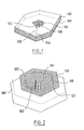
- FIG. 1 is a perspective view of an antenna of known type
- FIG. 2 is a perspective view of an antenna according to a first embodiment of the invention
- FIG. 3 is a view from above of an antenna according to a second embodiment of the invention.
- FIG. 4 represents the change, as a function of frequency, in the real part and imaginary part of an equivalent impedance of the antenna of FIG. 3;
- FIG. 5 represents the change, as a function of frequency, of a coefficient of reflection of the antenna of FIG. 3 in which two regions of matching can be counted;
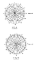
- FIG. 6 is an elevation radiation pattern at a first resonant frequency of the antenna of FIG. 3;
- FIG. 7 is an azimuth radiation pattern at a first resonant frequency of the antenna of FIG. 3;
- FIG. 8 is an elevation radiation pattern at a second resonant frequency of the antenna of FIG. 3;
- FIG. 9 is an azimuth radiation pattern at a second resonant frequency of the antenna of FIG. 3;
- FIG. 10 is a view from above of a capacitive top part of an antenna according to a third embodiment of the invention.
- the antenna of FIG. 2 adopts the main elements of the known antenna of FIG. 1.
- top part 120 that is defined by a series of rectilinear segments of any shape (polyhedron, circular, etc.).
- the capacitive top part 120 has a cutout-slot 122 that extends along the edges of this capacitive top part, thus forming a boundary between an edge region 124 of the top part and a central region 126 of the top part 120 .
- This cutout-slot is of a form that comes back round on itself, but is interrupted on a short stretch of the edge of the top part, such that it describes the general shape of a C. More specifically, the C that it describes is made up of a series of rectilinear portions, each parallel to a corresponding rectilinear edge of the capacitive top part, and the cutout-slot must not be closed up in order to keep a strip of metal exciting the outer antenna.
- the antenna has a ground wire 160 and a feed line 150 that extend transversely to the antenna, and that make contact with the top part 120 at its part that is enclosed by the C-shape cutout-slot.
- Adopting such a cutout-slot or slot 122 generates two capacitive effects: one at the top part edge 124 (outer part of the slot), and the other at the inner part 126 of the top part.
- cutout-slot 122 typically creates an additional resonance of the antenna at a neighboring wavelength of ⁇ f /2, where ⁇ f corresponds to the total length of the slot.
- the present antenna generates two resonances: one at the wavelength ⁇ corresponding to that of the wire-plate antenna having the region 126 inside the cutout-slot 122 as the capacitive top part, and the other resonance being at a smaller wavelength ⁇ f /2 generated by the presence of the cutout-slot 122 .
- This antenna exhibits a wire-plate type radiation at these two resonant frequencies.
- the presence of the cutout-slot 122 introduces new physical parameters that affect the electromagnetic behavior, that is to say the width of the cutout-slot 122 measured parallel to the plane of the capacitive top part and transversely to the cutout-slot 122 , the position of the cutout-slot 122 on the top part, the position of the cutout-slot 122 with respect to the feed wire 150 and with respect to the return wire 160 , and the length of the cutout-slot.
- the slot resonates (enabling the antenna to be matched) but does not radiate significantly since the radiation remains that of a wire-plate.
- the antenna has a disk-shaped ground plane 140 of diameter ⁇ /3 where ⁇ corresponds to the wavelength that would be obtained with a same antenna but whose top part would be solid.
- a square-shaped upper plate forms the capacitive top part 120 .
- This top part has a total width of ⁇ /6.
- the cutout-slot 122 fully runs along three of the sides of this square, and extends from its ends at the fourth side by a short portion each time.
- This second antenna with resonant cutout-slot also has a C-shape cutout-slot, this C being in this case perfectly symmetrical with respect to a plane that is transverse and median to the square top part.
- This C-shaped cutout-slot has a total length of around ⁇ f /2.
- the cutout-slot 122 runs along the edges of the capacitive top part 120 maintaining a constant distance from the edges. Thus, it defines a square internally and a strip 124 of constant width externally.
- ground wire 160 and the feed wire 150 are both placed substantially at the center of the inner square 126 in a plane of symmetry of the cutout-slot 122 , transverse to the antenna.
- Such an antenna has a resonance at the wavelength ⁇ , and also has a resonance approximately at the wavelength ⁇ f /2 which is specifically due to the cutout-slot 122 .
- the antenna therefore has two resonances.
- ground wire 160 and the feed wire 150 are in this case placed on a median plane forming a plane of symmetry of the cutout-slot 122 in order to maintain good symmetry in the diagram.
- such an antenna has an equivalent impedance, each exhibiting two peaks at two frequencies.
- both the real part and the imaginary part of the input impedance each have two peaks placed at these two frequencies respectively.
- the antenna has a reflection coefficient that also describes two peaks at these two same frequencies.
- the antenna has a good reflection coefficient, of about ⁇ 16 dB, at these two frequencies. It is therefore dual band.
- the antenna with cutout-slot in FIG. 3, does indeed have a monopolar radiation pattern at each of the two resonances.
- the maximum value of the gain is about 1.7 dB.
- a slight dissymmetry is observed on the elevation radiation pattern of the second resonance, and this is due to the dissymmetry of the slot with respect to an axis that is orthogonal to the wires 150 and 160 (more specifically with respect to a plane that is perpendicular to the plane of the wires, perpendicular to the antenna and median to the square formed by the upper plate 120 ).
- Such a dissymmetry may be corrected for example by adopting, in place of the previously proposed cutout-slot 122 one or more pairs of cutout-slots.
- FIG. 10 shows an upper plate 120 forming a capacitive top part and having two slots 122 , each in the shape of a C, and open one facing the other. These two C-shapes facing each other define in this case too an inner capacitive region 126 that is surrounded by both of them almost completely. They also define an outer strip 124 of constant width.
- Each of these C-shaped cutout-slots is formed by three rectilinear branches, each parallel with a side of the square formed by the plate 120 .
- the two cutout-slots 122 are perfectly symmetrical one with the other, each also being symmetrical with respect to itself such that an upper plate 120 is obtained that is physically symmetrical with respect to two planes that are transverse and median to the square.
- the feed wire 150 and the return wire 160 can be placed in one of these median planes and an electrical behavior can be obtained that is symmetrical with respect to the plane of these two wires.
- a first operating band corresponds appreciably to the wavelength ⁇ of an antenna the capacitive top part of which would be formed by the inner region 126 enclosed by the cutout-slots 122 , and the other operating frequency corresponds to a resonance close to ⁇ f /2 (half the abovementioned frequency) due to the cutout-slots 122 of same dimensions.
- two (or more) cutout-slots are adopted having similar but not equal dimensions and/or having similar but not equal positionings.
- two (or more) resonance peaks are obtained in addition to the wire-plate resonance. These two peaks are close to each other but not equal and they partially overlap, thereby generating in practice a widened frequency band that is additional to the effective operating frequency of the inner region 126 .
- two or more cutout-slots are adopted that extend one with respect to the other and that have dimensions that are sufficiently different to obtain two or more clearly different resonances which are additional with respect to the wire-plate resonance.
- cutout-slots The purpose of the cutout-slots is to create several overlapped wire-plate antennas, each wire-plate antenna formed substantially of the regions bounded by the cutout-slot and of the ground return, collective or otherwise, of the antenna.
- cutout-slots do not change the mode of radiation of each wire-plate antenna considered, which mode remains omnidirectional in azimuth since the slots are not sites for electromagnetic resonance at the frequencies considered.
- These antennas can be used to produce, for example, a matched aerial; they advantageously form multi-band antennas (for example for transmission and reception), for example with peaks that are close together in frequency, or even widened band antennas by having peaks that are sufficiently tightly close to one another.
- These antennas enable the use of several frequency bands for mobile telephony, for example: GSM, DCS, DECT, or for use inside buildings (indoor use).
- the various frequency bands obtained can be used for uplink or downlink paths, for example for transmission and reception in ARGOS tags.
- Such antennas can also be used for AMPS-PCS 1900 applications.
Landscapes
- Waveguide Aerials (AREA)
- Details Of Aerials (AREA)
Abstract
Description
- The invention relates to the field of antennas, and more specifically the field of wire-plate antennas.
- Wire-plate antennas are known that consist, as represented in FIG. 1, of a metal plate 120 (capacitive top part of the antenna) having, in principle, arbitrary shape, of a
dielectric layer 130 bearing this plate on its upper face and of aground plane 140 produced by lower metallization of the dielectric layer. - The feed for such an antenna is typically realized by a
coaxial line 150 which passes through theground plane 140, aninner conductor 152 of which is connected to the metaltop part 120 and anouter conductor 154 of which is connected to theground plane 140. The particular aspect of such an antenna is that of having awire 160 connecting the capacitivetop part 120 and theground plane 140, forming an active metal return to ground. - The return-to-
ground wire 160 gives rise to a “parallel” resonance at a frequency less than that of a “fundamental” frequency of a patch. - This parallel resonance is due to an exchange of energy between the self inductance L and the capacitance C of a resonator formed by the return-to-ground wire (inductive effect λ) and the capacitive top part.
- A resonant frequency is then obtained, thus giving a range of matching of the antenna, of the type:

- The physical parameters affecting this frequency are the permittivity of the dielectric substrate ε r, its height (distance between the top part and the ground plane), the radius of the
feed line 150, the radius of the return-to-ground wire 140, the distance between thefeed line 150 and the return-to-ground wire 160, and the dimensions of thetop part 120 and of theground plane 140. - This large number of parameters multiplies by as much the number of possible configurations, enabling the antennas to be optimized to meet performance specifications.
- The wire-plate antenna radiation arises mainly from the
return wires 160 and exhibits the typical characteristics of radiation from a monopole perpendicular to the ground plane, the characteristic radiation being an omnidirectional azimuth radiation with respect to the ground plane and almost zero perpendicular to this plane. - Thus, such an antenna exhibits a radiation pattern having a lobe with rotational symmetry, with maximum radiation directed approximately parallel to the ground plane and a minimum radiation in the axis of the feed and return wires. In accordance with the typical radiation of a monopole perpendicular to the ground plane. It is to be noted that in the case of finite ground planes, the effects of diffraction through the breaks in the
ground plane 140 introduce distortions of the radiation pattern and a backward radiation. - The operation of a wire-plate antenna is therefore very different from the operation of another type of antenna known as a “resonant antenna”. This is because, the resonance referred to for these “resonant antennas” is an electromagnetic type resonance (resonant modes) and not an electric type resonance as is the case for wire-plate antennas. This is because, in wire-plate antennas, the resonant elements are localized, similar to electrical components.
- Operation by electrical resonance and the use of structures like electrical components results in wire-plate antennas having a dimension much smaller than the wavelength, and in any case having dimensions smaller than the smallest dimensions of “resonant antennas”.
- The operation of wire-plate antennas is therefore very different from electromagnetic resonance operation that governs the antennas referred to as “resonant antennas”.
- The operation of wire-plate antennas distinguishes them in particular from “microstrip” or “microslot” antennas known to those skilled in the art.
- Despite the existence of many possibilities in choosing physical parameters to best adapt the known antenna to performance specifications, in practise it is desirable to have an antenna that is still more easily configurable, at its construction stage, in accordance with the multiband, multifunction behavior desired.
- This aim is achieved according to the invention by virtue of an antenna of the type comprising:
- a first electrically-conductive surface;
- a second electrically-conductive surface, forming a ground plane, parallel to the first surface;
- a first electrically-conductive feed wire or strip connecting a first terminal of a generator/receiver to the first surface;
- the second surface being connected to a second terminal of the generator/receiver; and
- at least one second electrically-conductive wire or strip connecting the two abovementioned surfaces,
- characterized in that the first surface has a cutout-slot, or a series of cutout-slots, each cutout-slot being formed, possibly, of mutually extending sections, this (or these) cutout-slot(s) stretching to near and along an edge part of this first surface, this edge part being sufficiently extensive in order that the cutout-slot(s) defines an inner region of the first surface by substantially forming most of the periphery of this region, thereby achieving a multi-frequency wire-plate operation.
- These cutout-slots generate different capacitances leading to different resonant frequencies of the wire-plate antenna in accordance with the previously mentioned formula.
- Preserving the wire-plate radiation (that is to say omnidirectional azimuth) also distinguishes this antenna from those encountered in literature for which antennas it is the cutout-slot in the surface that radiates with a maximum in the axis perpendicular to this surface and not a very weak radiation in this direction as is the case for a wire-plate antenna and especially in the invention.
- Advantageously, the first surface has a cutout-slot of very small width with respect to its length and to the main wavelength picked up (preferably a tenth of this length). There may be several cutout-slots, for example greater than two in number.
- According to advantageous but non-limiting arrangements:
- the cutout-slot(s) of the first surface has (have) very small widths in comparison with its (their) length and with the operating wavelengths;
- said at least one second electrically-conductive wire or strip connecting the first and second surfaces makes contact with the first surface inside said region, and preferably in the middle of the antenna, which region is surrounded mostly by the cutout-slot(s);
- said first electrically-conductive feed wire or strip connecting a first terminal of a generator/receiver to the first surface makes contact with this first surface inside said region which is mostly surrounded by the cutout-slot(s);
- the first and second surfaces are arranged one facing the other and in parallel with each other, in that the first and second electrically-conductive wires or strips extend one parallel with the other and perpendicularly to the planes of the two surfaces, and in that the cutout-slot or series of cutout-slots forms two designs that are perfectly symmetrical with respect to a geometric plane passing through these two conductive wires or strips;
- the first surface has a cutout-slot formed of two sections each having the shape of a C, with one open part of the C-shape facing the other;
- the two sections are symmetrical with each other with respect to a first geometric plane passing between these two sections and in that each section is symmetrical with itself with respect to a second geometric plane passing through the centers of these two cutout-slots;
- the first surface has at least two cutout-slots each having respective shapes that are sufficiently similar in order that these two cutout-slots generate two peaks of electromagnetic effectiveness on the wire-plate mode, mixed at the same frequency;
- the first surface has at least two cutout-slots and in that these two cutout-slots have respective shapes that are sufficiently similar such that these two cutout-slots generate two electromagnetic effective-operation peaks on the wire-plate mode, which overlap frequencywise, thus forming a widened effective operating in frequency band;
- the first surface has at least two cutout-slots having sufficiently different shapes in order that these cutout-slots generate at least two effective operating frequency regions, on the wire-plate mode, of the antenna which do not overlap one another;
- the first surface is defined by any type of shape, and in that the cutout-slot or cutout-slots remain parallel to the edge of this shape;
- one of the surfaces forming the ground plane includes one or more cutout-slots of the same type as for the first surface;
- the surfaces are substantially identical and the same operation is observed due to the fact that the cutout-slots are present in the ground plane;
- the ground plane is markedly larger than the first surface, the frequencies generated being the same, but the radiation patterns being different, due to the presence of the ground plane;
- it includes one or more dielectric or magnetic layers between the surface forming the ground plane and the first surface and also above the two surfaces (radome);
- the antenna comprises superposed top parts and intermediate planes, the cutout-slots being made in any intermediate plane, and dielectric or magnetic materials being interposed for rigidity or tunability or miniaturization.
- Other features, aims and advantages of the invention will become apparent from reading the detailed description that follows, made with reference to the accompanying figures in which:
- FIG. 1 is a perspective view of an antenna of known type;
- FIG. 2 is a perspective view of an antenna according to a first embodiment of the invention;
- FIG. 3 is a view from above of an antenna according to a second embodiment of the invention;
- FIG. 4 represents the change, as a function of frequency, in the real part and imaginary part of an equivalent impedance of the antenna of FIG. 3;
- FIG. 5 represents the change, as a function of frequency, of a coefficient of reflection of the antenna of FIG. 3 in which two regions of matching can be counted;
- FIG. 6 is an elevation radiation pattern at a first resonant frequency of the antenna of FIG. 3;
- FIG. 7 is an azimuth radiation pattern at a first resonant frequency of the antenna of FIG. 3;
- FIG. 8 is an elevation radiation pattern at a second resonant frequency of the antenna of FIG. 3;
- FIG. 9 is an azimuth radiation pattern at a second resonant frequency of the antenna of FIG. 3;
- FIG. 10 is a view from above of a capacitive top part of an antenna according to a third embodiment of the invention.
- The antenna of FIG. 2 adopts the main elements of the known antenna of FIG. 1.
- It has a
top part 120 that is defined by a series of rectilinear segments of any shape (polyhedron, circular, etc.). - However, in this case, the capacitive
top part 120 has a cutout-slot 122 that extends along the edges of this capacitive top part, thus forming a boundary between anedge region 124 of the top part and acentral region 126 of thetop part 120. - This cutout-slot is of a form that comes back round on itself, but is interrupted on a short stretch of the edge of the top part, such that it describes the general shape of a C. More specifically, the C that it describes is made up of a series of rectilinear portions, each parallel to a corresponding rectilinear edge of the capacitive top part, and the cutout-slot must not be closed up in order to keep a strip of metal exciting the outer antenna.
- The antenna has a
ground wire 160 and afeed line 150 that extend transversely to the antenna, and that make contact with thetop part 120 at its part that is enclosed by the C-shape cutout-slot. - Adopting such a cutout-slot or
slot 122 generates two capacitive effects: one at the top part edge 124 (outer part of the slot), and the other at theinner part 126 of the top part. - The addition of such a cutout-
slot 122 typically creates an additional resonance of the antenna at a neighboring wavelength of λf/2, where λf corresponds to the total length of the slot. - Thus, the present antenna generates two resonances: one at the wavelength λ corresponding to that of the wire-plate antenna having the
region 126 inside the cutout-slot 122 as the capacitive top part, and the other resonance being at a smaller wavelength λf/2 generated by the presence of the cutout-slot 122. - This antenna exhibits a wire-plate type radiation at these two resonant frequencies.
- More specifically, the presence of the cutout-
slot 122 introduces new physical parameters that affect the electromagnetic behavior, that is to say the width of the cutout-slot 122 measured parallel to the plane of the capacitive top part and transversely to the cutout-slot 122, the position of the cutout-slot 122 on the top part, the position of the cutout-slot 122 with respect to thefeed wire 150 and with respect to thereturn wire 160, and the length of the cutout-slot. - These physical parameters then supplement the physical parameters that normally affect the behavior of antennas, and multiply the number of possible configurations of the antenna enabling the antenna to be better adapted to the use envisaged, in particular by the dual resonance.
- As will be seen later, the slot resonates (enabling the antenna to be matched) but does not radiate significantly since the radiation remains that of a wire-plate.
- In the embodiment of FIG. 3, the antenna has a disk-shaped
ground plane 140 of diameter λ/3 where λ corresponds to the wavelength that would be obtained with a same antenna but whose top part would be solid. A square-shaped upper plate forms the capacitivetop part 120. This top part has a total width of λ/6. The cutout-slot 122 fully runs along three of the sides of this square, and extends from its ends at the fourth side by a short portion each time. - This second antenna with resonant cutout-slot also has a C-shape cutout-slot, this C being in this case perfectly symmetrical with respect to a plane that is transverse and median to the square top part. This C-shaped cutout-slot has a total length of around λ f/2.
- The cutout-
slot 122 runs along the edges of the capacitivetop part 120 maintaining a constant distance from the edges. Thus, it defines a square internally and astrip 124 of constant width externally. - The
ground wire 160 and thefeed wire 150 are both placed substantially at the center of theinner square 126 in a plane of symmetry of the cutout-slot 122, transverse to the antenna. - Such an antenna has a resonance at the wavelength λ, and also has a resonance approximately at the wavelength λ f/2 which is specifically due to the cutout-
slot 122. The antenna therefore has two resonances. - The
ground wire 160 and thefeed wire 150 are in this case placed on a median plane forming a plane of symmetry of the cutout-slot 122 in order to maintain good symmetry in the diagram. - As shown in FIG. 4, such an antenna has an equivalent impedance, each exhibiting two peaks at two frequencies.
- More specifically, as represented in FIG. 4, both the real part and the imaginary part of the input impedance each have two peaks placed at these two frequencies respectively.
- As illustrated in FIG. 5, the antenna has a reflection coefficient that also describes two peaks at these two same frequencies. The antenna has a good reflection coefficient, of about −16 dB, at these two frequencies. It is therefore dual band.
- As illustrated in FIGS. 6 to 9, the antenna with cutout-slot, in FIG. 3, does indeed have a monopolar radiation pattern at each of the two resonances. The maximum value of the gain is about 1.7 dB.
- A slight dissymmetry is observed on the elevation radiation pattern of the second resonance, and this is due to the dissymmetry of the slot with respect to an axis that is orthogonal to the
wires 150 and 160 (more specifically with respect to a plane that is perpendicular to the plane of the wires, perpendicular to the antenna and median to the square formed by the upper plate 120). - Such a dissymmetry may be corrected for example by adopting, in place of the previously proposed cutout-
slot 122 one or more pairs of cutout-slots. - Thus, FIG. 10 shows an
upper plate 120 forming a capacitive top part and having twoslots 122, each in the shape of a C, and open one facing the other. These two C-shapes facing each other define in this case too aninner capacitive region 126 that is surrounded by both of them almost completely. They also define anouter strip 124 of constant width. - Each of these C-shaped cutout-slots is formed by three rectilinear branches, each parallel with a side of the square formed by the
plate 120. Thus, the two cutout-slots 122 are perfectly symmetrical one with the other, each also being symmetrical with respect to itself such that anupper plate 120 is obtained that is physically symmetrical with respect to two planes that are transverse and median to the square. - The
feed wire 150 and thereturn wire 160 can be placed in one of these median planes and an electrical behavior can be obtained that is symmetrical with respect to the plane of these two wires. - In other words, cutting out on the
top part 120 two cutout-slots 122 of the same dimensions results in making the radiation pattern symmetrical while maintaining two operating frequency bands. - A first operating band corresponds appreciably to the wavelength λ of an antenna the capacitive top part of which would be formed by the
inner region 126 enclosed by the cutout-slots 122, and the other operating frequency corresponds to a resonance close to λf/2 (half the abovementioned frequency) due to the cutout-slots 122 of same dimensions. - According to one variant, two (or more) cutout-slots are adopted having similar but not equal dimensions and/or having similar but not equal positionings. In this variant, two (or more) resonance peaks are obtained in addition to the wire-plate resonance. These two peaks are close to each other but not equal and they partially overlap, thereby generating in practice a widened frequency band that is additional to the effective operating frequency of the
inner region 126. - According to yet another variant, two or more cutout-slots are adopted that extend one with respect to the other and that have dimensions that are sufficiently different to obtain two or more clearly different resonances which are additional with respect to the wire-plate resonance.
- Radiation patterns similar to those of known antennas are obtained, but several different frequency bands.
- The purpose of the cutout-slots is to create several overlapped wire-plate antennas, each wire-plate antenna formed substantially of the regions bounded by the cutout-slot and of the ground return, collective or otherwise, of the antenna.
- The cutout-slots do not change the mode of radiation of each wire-plate antenna considered, which mode remains omnidirectional in azimuth since the slots are not sites for electromagnetic resonance at the frequencies considered.
- The various antennas described previously have similar polarizations at their various resonant frequencies.
- The various antennas proposed here supply, in addition to the advantages of the conventional wire-plate antenna, the advantage of exhibiting one or more new resonances, while being of a similar size to known antennas.
- These antennas can be used to produce, for example, a matched aerial; they advantageously form multi-band antennas (for example for transmission and reception), for example with peaks that are close together in frequency, or even widened band antennas by having peaks that are sufficiently tightly close to one another.
- These antennas enable the use of several frequency bands for mobile telephony, for example: GSM, DCS, DECT, or for use inside buildings (indoor use).
- The various frequency bands obtained can be used for uplink or downlink paths, for example for transmission and reception in ARGOS tags. Such antennas can also be used for AMPS-PCS 1900 applications.
Claims (16)
Applications Claiming Priority (3)
| Application Number | Priority Date | Filing Date | Title |
|---|---|---|---|
| FR0107940A FR2826185B1 (en) | 2001-06-18 | 2001-06-18 | MULTI-FREQUENCY WIRE-PLATE ANTENNA |
| FR01/07940 | 2002-06-18 | ||
| PCT/FR2002/002090 WO2002103843A1 (en) | 2001-06-18 | 2002-06-18 | Multi-frequency wire-plate antenna |
Publications (2)
| Publication Number | Publication Date |
|---|---|
| US20040164916A1 true US20040164916A1 (en) | 2004-08-26 |
| US7038631B2 US7038631B2 (en) | 2006-05-02 |
Family
ID=8864421
Family Applications (1)
| Application Number | Title | Priority Date | Filing Date |
|---|---|---|---|
| US10/481,122 Expired - Lifetime US7038631B2 (en) | 2001-06-18 | 2002-06-18 | Multi-frequency wire-plate antenna |
Country Status (6)
| Country | Link |
|---|---|
| US (1) | US7038631B2 (en) |
| EP (1) | EP1433223B1 (en) |
| JP (1) | JP4044895B2 (en) |
| CA (1) | CA2451097C (en) |
| FR (1) | FR2826185B1 (en) |
| WO (1) | WO2002103843A1 (en) |
Cited By (7)
| Publication number | Priority date | Publication date | Assignee | Title |
|---|---|---|---|---|
| US20040135728A1 (en) * | 2002-12-27 | 2004-07-15 | Honda Motor Co., Ltd. | On-board antenna |
| US20120044116A1 (en) * | 2008-04-10 | 2012-02-23 | Bing Chiang | Slot antennas for electronic devices |
| US8368602B2 (en) | 2010-06-03 | 2013-02-05 | Apple Inc. | Parallel-fed equal current density dipole antenna |
| EP3185360A1 (en) * | 2015-12-22 | 2017-06-28 | Safemine AG | Multiband, monopole antenna assembly |
| US10263327B1 (en) * | 2018-06-11 | 2019-04-16 | Gaodi ZOU | Anti-interference microwave antenna |
| US10411337B2 (en) | 2014-12-10 | 2019-09-10 | Denso Corporation | Antenna device |
| CN112310620A (en) * | 2019-08-02 | 2021-02-02 | 原田工业株式会社 | Laminated patch antenna |
Families Citing this family (23)
| Publication number | Priority date | Publication date | Assignee | Title |
|---|---|---|---|---|
| DE29925006U1 (en) | 1999-09-20 | 2008-04-03 | Fractus, S.A. | Multilevel antenna |
| FR2826186B1 (en) * | 2001-06-18 | 2003-10-10 | Centre Nat Rech Scient | MULTI-FUNCTIONAL ANTENNA INCLUDING WIRE-PLATE ASSEMBLIES |
| JP2005039754A (en) * | 2003-06-26 | 2005-02-10 | Alps Electric Co Ltd | Antenna system |
| US7050009B2 (en) | 2003-07-22 | 2006-05-23 | Psion Teklogix Inc. | Internal antenna |
| ITVI20030270A1 (en) * | 2003-12-31 | 2005-07-01 | Calearo Antenne Srl | MULTI-BAY AFT OF SLOTS |
| JP4280182B2 (en) * | 2004-03-09 | 2009-06-17 | 富士通コンポーネント株式会社 | Antenna device |
| CA2505433A1 (en) * | 2004-04-27 | 2005-10-27 | Intelwaves Technologies Ltd. | Low profile hybrid phased array antenna system configuration and element |
| JP3930015B2 (en) * | 2004-12-09 | 2007-06-13 | 松下電器産業株式会社 | Antenna device for wireless device and portable wireless device including the same |
| JP3889423B2 (en) * | 2004-12-16 | 2007-03-07 | 松下電器産業株式会社 | Polarization switching antenna device |
| US7199761B2 (en) * | 2005-08-10 | 2007-04-03 | Motorola Inc. | Wireless communication device with improved antenna system |
| DE102005055345A1 (en) | 2005-11-21 | 2007-05-24 | Robert Bosch Gmbh | Multiband omnidirectional |
| US7427957B2 (en) * | 2007-02-23 | 2008-09-23 | Mark Iv Ivhs, Inc. | Patch antenna |
| US7612725B2 (en) * | 2007-06-21 | 2009-11-03 | Apple Inc. | Antennas for handheld electronic devices with conductive bezels |
| JP4437167B2 (en) * | 2008-04-21 | 2010-03-24 | パナソニック株式会社 | ANTENNA DEVICE AND WIRELESS COMMUNICATION DEVICE |
| JP2013098791A (en) * | 2011-11-01 | 2013-05-20 | Mitsubishi Cable Ind Ltd | Antenna |
| CN104466380B (en) * | 2014-12-19 | 2017-06-27 | 南京理工大学 | Planar Dual Frequency Dual Circular Polarization Array Antenna |
| JP6528496B2 (en) * | 2015-03-23 | 2019-06-12 | 株式会社Soken | Antenna device |
| KR101660921B1 (en) * | 2015-08-11 | 2016-09-28 | 한국전자통신연구원 | Circularly polarized global positioning system antennas using parasitic strip lines |
| US10206649B2 (en) * | 2015-12-29 | 2019-02-19 | Analogic Corporation | Data transfer across a rotating boundary of a computed tomography imaging apparatus |
| JP6705435B2 (en) * | 2017-10-27 | 2020-06-03 | Tdk株式会社 | Patch antenna and antenna module including the same |
| JP6341399B1 (en) * | 2018-03-14 | 2018-06-13 | パナソニックIpマネジメント株式会社 | Antenna device |
| KR102572247B1 (en) | 2018-11-14 | 2023-08-29 | 삼성전자주식회사 | Antenna using slot and electronic device including the same |
| WO2022064682A1 (en) * | 2020-09-28 | 2022-03-31 | 三菱電機株式会社 | Composite antenna device |
Citations (10)
| Publication number | Priority date | Publication date | Assignee | Title |
|---|---|---|---|---|
| US4771291A (en) * | 1985-08-30 | 1988-09-13 | The United States Of America As Represented By The Secretary Of The Air Force | Dual frequency microstrip antenna |
| US6014105A (en) * | 1999-01-19 | 2000-01-11 | The United States Of America As Represented By The Secretary Of The Navy | Microstrip antenna having an internal feed |
| US6133879A (en) * | 1997-12-11 | 2000-10-17 | Alcatel | Multifrequency microstrip antenna and a device including said antenna |
| US6195048B1 (en) * | 1997-12-01 | 2001-02-27 | Kabushiki Kaisha Toshiba | Multifrequency inverted F-type antenna |
| US20020003499A1 (en) * | 2000-07-10 | 2002-01-10 | Alcatel | Antenna with a conductive layer and a two-band transmitter including the antenna |
| US6348892B1 (en) * | 1999-10-20 | 2002-02-19 | Filtronic Lk Oy | Internal antenna for an apparatus |
| US6529168B2 (en) * | 2000-10-27 | 2003-03-04 | Filtronic Lk Oy | Double-action antenna |
| US6624788B2 (en) * | 2001-01-23 | 2003-09-23 | Koninklijke Philips Electronisc N.V. | Antenna arrangement |
| US6646610B2 (en) * | 2001-12-21 | 2003-11-11 | Nokia Corporation | Antenna |
| US6759991B2 (en) * | 2001-03-06 | 2004-07-06 | Koninklijke Philips Electronics N.V. | Antenna arrangement |
Family Cites Families (1)
| Publication number | Priority date | Publication date | Assignee | Title |
|---|---|---|---|---|
| US6343208B1 (en) * | 1998-12-16 | 2002-01-29 | Telefonaktiebolaget Lm Ericsson (Publ) | Printed multi-band patch antenna |
-
2001
- 2001-06-18 FR FR0107940A patent/FR2826185B1/en not_active Expired - Fee Related
-
2002
- 2002-06-18 WO PCT/FR2002/002090 patent/WO2002103843A1/en not_active Ceased
- 2002-06-18 US US10/481,122 patent/US7038631B2/en not_active Expired - Lifetime
- 2002-06-18 JP JP2003506045A patent/JP4044895B2/en not_active Expired - Fee Related
- 2002-06-18 EP EP02751260.7A patent/EP1433223B1/en not_active Expired - Lifetime
- 2002-06-18 CA CA002451097A patent/CA2451097C/en not_active Expired - Fee Related
Patent Citations (10)
| Publication number | Priority date | Publication date | Assignee | Title |
|---|---|---|---|---|
| US4771291A (en) * | 1985-08-30 | 1988-09-13 | The United States Of America As Represented By The Secretary Of The Air Force | Dual frequency microstrip antenna |
| US6195048B1 (en) * | 1997-12-01 | 2001-02-27 | Kabushiki Kaisha Toshiba | Multifrequency inverted F-type antenna |
| US6133879A (en) * | 1997-12-11 | 2000-10-17 | Alcatel | Multifrequency microstrip antenna and a device including said antenna |
| US6014105A (en) * | 1999-01-19 | 2000-01-11 | The United States Of America As Represented By The Secretary Of The Navy | Microstrip antenna having an internal feed |
| US6348892B1 (en) * | 1999-10-20 | 2002-02-19 | Filtronic Lk Oy | Internal antenna for an apparatus |
| US20020003499A1 (en) * | 2000-07-10 | 2002-01-10 | Alcatel | Antenna with a conductive layer and a two-band transmitter including the antenna |
| US6529168B2 (en) * | 2000-10-27 | 2003-03-04 | Filtronic Lk Oy | Double-action antenna |
| US6624788B2 (en) * | 2001-01-23 | 2003-09-23 | Koninklijke Philips Electronisc N.V. | Antenna arrangement |
| US6759991B2 (en) * | 2001-03-06 | 2004-07-06 | Koninklijke Philips Electronics N.V. | Antenna arrangement |
| US6646610B2 (en) * | 2001-12-21 | 2003-11-11 | Nokia Corporation | Antenna |
Cited By (10)
| Publication number | Priority date | Publication date | Assignee | Title |
|---|---|---|---|---|
| US20040135728A1 (en) * | 2002-12-27 | 2004-07-15 | Honda Motor Co., Ltd. | On-board antenna |
| US7019699B2 (en) * | 2002-12-27 | 2006-03-28 | Honda Motor Co., Ltd. | On-board antenna |
| US20120044116A1 (en) * | 2008-04-10 | 2012-02-23 | Bing Chiang | Slot antennas for electronic devices |
| US8223082B2 (en) * | 2008-04-10 | 2012-07-17 | Apple Inc. | Slot antennas for electronic devices |
| US8368602B2 (en) | 2010-06-03 | 2013-02-05 | Apple Inc. | Parallel-fed equal current density dipole antenna |
| US10411337B2 (en) | 2014-12-10 | 2019-09-10 | Denso Corporation | Antenna device |
| EP3185360A1 (en) * | 2015-12-22 | 2017-06-28 | Safemine AG | Multiband, monopole antenna assembly |
| US10096894B2 (en) | 2015-12-22 | 2018-10-09 | Safemine Ag | Multiband, monopole antenna assembly |
| US10263327B1 (en) * | 2018-06-11 | 2019-04-16 | Gaodi ZOU | Anti-interference microwave antenna |
| CN112310620A (en) * | 2019-08-02 | 2021-02-02 | 原田工业株式会社 | Laminated patch antenna |
Also Published As
| Publication number | Publication date |
|---|---|
| WO2002103843A1 (en) | 2002-12-27 |
| US7038631B2 (en) | 2006-05-02 |
| JP2004531152A (en) | 2004-10-07 |
| CA2451097C (en) | 2008-01-15 |
| JP4044895B2 (en) | 2008-02-06 |
| EP1433223B1 (en) | 2015-04-15 |
| FR2826185B1 (en) | 2008-07-11 |
| EP1433223A1 (en) | 2004-06-30 |
| FR2826185A1 (en) | 2002-12-20 |
| CA2451097A1 (en) | 2002-12-27 |
Similar Documents
| Publication | Publication Date | Title |
|---|---|---|
| US7038631B2 (en) | Multi-frequency wire-plate antenna | |
| Emadian et al. | Very small dual band-notched rectangular slot antenna with enhanced impedance bandwidth | |
| Patel et al. | An electrically small antenna using defected ground structure for RFID, GPS and IEEE 802.11 a/b/g/s applications | |
| CN109149131B (en) | Dipole antenna and associated multiband antenna | |
| Pan et al. | Wideband and low-profile omnidirectional circularly polarized patch antenna | |
| US8610635B2 (en) | Balanced metamaterial antenna device | |
| US6975278B2 (en) | Multiband branch radiator antenna element | |
| Singh et al. | Miniaturized multiband microstrip patch antenna using metamaterial loading for wireless application | |
| US20150303576A1 (en) | Miniaturized Patch Antenna | |
| KR101489182B1 (en) | Infinite wavelength antenna device | |
| Kumar et al. | A high gain wideband circularly polarized microstrip antenna | |
| JP4021642B2 (en) | Antenna structure and radio apparatus | |
| JP2005508099A (en) | Multiband antenna for mobile equipment | |
| Trimukhe et al. | Compact ultra-wideband antenna with triple band notch characteristics using EBG structures | |
| CN106067590A (en) | Double-frequency omnidirectional substrate integrated waveguide spiral slot antenna | |
| US20050237255A1 (en) | Small footprint dual band dipole antennas for wireless networking | |
| US11664598B2 (en) | Omnidirectional dielectric resonator antenna | |
| KR101040084B1 (en) | Frequency selective surface unit cell and surface wave suppression apparatus using the same | |
| US20060164303A1 (en) | Multiband planar antenna | |
| Naghshvarian-Jahromi et al. | Analysis of the behavior of Sierpinski carpet monopole antenna | |
| Behara et al. | Moore curve fractal-shaped frequency selective surface for multiband applications | |
| Hamid et al. | Wideband reconfigurable log periodic patch array | |
| CN118315797A (en) | Patch antenna and terminal equipment | |
| Boutejdar et al. | Design of multiband microstrip antenna using stepped cut method for WLAN/WiMAX and C/Ku-Band Applications | |
| KR100939478B1 (en) | Micro flat station chip antenna |
Legal Events
| Date | Code | Title | Description |
|---|---|---|---|
| AS | Assignment |
Owner name: CENTRE NATIONAL DE LA RECHERCHE SCIENTIFIQUE (CNRS Free format text: ASSIGNMENT OF ASSIGNORS INTEREST;ASSIGNORS:JECKO, BERNARD JEAN YVES;HAMMOUDI, MOHAMED;REEL/FRAME:016799/0383;SIGNING DATES FROM 20051110 TO 20051111 |
|
| STCF | Information on status: patent grant |
Free format text: PATENTED CASE |
|
| FEPP | Fee payment procedure |
Free format text: PAYOR NUMBER ASSIGNED (ORIGINAL EVENT CODE: ASPN); ENTITY STATUS OF PATENT OWNER: LARGE ENTITY |
|
| FPAY | Fee payment |
Year of fee payment: 4 |
|
| FPAY | Fee payment |
Year of fee payment: 8 |
|
| MAFP | Maintenance fee payment |
Free format text: PAYMENT OF MAINTENANCE FEE, 12TH YEAR, LARGE ENTITY (ORIGINAL EVENT CODE: M1553) Year of fee payment: 12 |