US20040148336A1 - Massively distributed processing system architecture, scheduling, unique device identification and associated methods - Google Patents
Massively distributed processing system architecture, scheduling, unique device identification and associated methods Download PDFInfo
- Publication number
- US20040148336A1 US20040148336A1 US10/402,331 US40233103A US2004148336A1 US 20040148336 A1 US20040148336 A1 US 20040148336A1 US 40233103 A US40233103 A US 40233103A US 2004148336 A1 US2004148336 A1 US 2004148336A1
- Authority
- US
- United States
- Prior art keywords
- distributed
- client
- systems
- processing system
- project
- Prior art date
- Legal status (The legal status is an assumption and is not a legal conclusion. Google has not performed a legal analysis and makes no representation as to the accuracy of the status listed.)
- Abandoned
Links
Images


Classifications
-
- G—PHYSICS
- G06—COMPUTING; CALCULATING OR COUNTING
- G06Q—INFORMATION AND COMMUNICATION TECHNOLOGY [ICT] SPECIALLY ADAPTED FOR ADMINISTRATIVE, COMMERCIAL, FINANCIAL, MANAGERIAL OR SUPERVISORY PURPOSES; SYSTEMS OR METHODS SPECIALLY ADAPTED FOR ADMINISTRATIVE, COMMERCIAL, FINANCIAL, MANAGERIAL OR SUPERVISORY PURPOSES, NOT OTHERWISE PROVIDED FOR
- G06Q10/00—Administration; Management
- G06Q10/06—Resources, workflows, human or project management; Enterprise or organisation planning; Enterprise or organisation modelling
-
- G—PHYSICS
- G06—COMPUTING; CALCULATING OR COUNTING
- G06Q—INFORMATION AND COMMUNICATION TECHNOLOGY [ICT] SPECIALLY ADAPTED FOR ADMINISTRATIVE, COMMERCIAL, FINANCIAL, MANAGERIAL OR SUPERVISORY PURPOSES; SYSTEMS OR METHODS SPECIALLY ADAPTED FOR ADMINISTRATIVE, COMMERCIAL, FINANCIAL, MANAGERIAL OR SUPERVISORY PURPOSES, NOT OTHERWISE PROVIDED FOR
- G06Q30/00—Commerce
- G06Q30/02—Marketing; Price estimation or determination; Fundraising
Landscapes
- Business, Economics & Management (AREA)
- Engineering & Computer Science (AREA)
- Strategic Management (AREA)
- Development Economics (AREA)
- Economics (AREA)
- Entrepreneurship & Innovation (AREA)
- General Physics & Mathematics (AREA)
- Theoretical Computer Science (AREA)
- Game Theory and Decision Science (AREA)
- Marketing (AREA)
- Finance (AREA)
- Accounting & Taxation (AREA)
- Human Resources & Organizations (AREA)
- Physics & Mathematics (AREA)
- General Business, Economics & Management (AREA)
- Educational Administration (AREA)
- Tourism & Hospitality (AREA)
- Quality & Reliability (AREA)
- Operations Research (AREA)
- Multi Processors (AREA)
Abstract
Description
- This application is a continuation-in-part application of the following co-pending applications: application Ser. No. 09/539,448 entitled “CAPABILITY-BASED DISTRIBUTED PARALLEL PROCESING SYSTEM AND ASSOCIATED METHOD,” application Ser. No 09/539,428 entitled “METHOD OF MANAGING DISTRIBUTED WORKLOADS AND ASSOCIATED SYSTEM,” and application Ser. No. 09/539,106 entitled “NETWORK SITE TESTING METHOD AND ASSOCIATED SYSTEM,” each of which was filed on Mar. 30, 2000, and each of which is hereby incorporated by reference in its entirety. This application is also a continuation-in-part application of the following co-pending application: application Ser. No. 09/603,740 entitled “METHOD OF MANAGING WORKLOADS AND ASSOCIATED DISTRIBUTED PROCESSING SYSTEM,” and application Ser. No. 09/602,983 entitled “CUSTOMER SERVICES AND ADVERTISING BASED UPON DEVICE ATTRIBUTES AND ASSOCIATED DISTRIBUTED PROCESSING SYSTEM,” each of which was filed on Jun. 23, 2000, and each of which is hereby incorporated by reference in its entirety. This application is also a continuation-in-part application of the following co-pending application: application Ser. No. 09/648,832 entitled “SECURITY ARCHITECTURE FOR DISTRIBUTED PROCESSING SYSTEMS AND ASSOCIATED METHOD,” which was filed on Aug. 25, 2000, and which is hereby incorporated by reference in its entirety. This application is also a continuation-in-part application of the following co-pending application: application Ser. No. 09/794,969 entitled “SYSTEM AND METHOD FOR MONITIZING NETWORK CONNECTED USER BASES UTILIZING DISTRIBUTED PROCESSING SYSTEMS,” which was filed on Feb. 27, 2001, and which is hereby incorporated by reference in its entirety. This application is also a continuation-in-part application of the following co-pending application: application Ser. No. 09/834,785 entitled “SOFTWARE-BASED NETWORK ATTACHED STORAGE SERVICES HOSTED ON MASSIVELY DISTRIBUTED PARALLEL COMPUTING NETWORKS,” which was filed on Apr. 13, 2001, and which is hereby incorporated by reference in its entirety. This application is also a continuation-in-part application of the following co-pending application: application Ser. No. 10/186,266 entitled “DYNAMIC COORDINATION AND CONTROL OF NETWORK CONNECTED DEVICES FOR LARGE-SCALE NETWORK SITE TESTING AND ASSOCIATED ARCHITECTURES,” which was filed on Jun. 27, 2002, and which is hereby incorporated by reference in its entirety. The present application also claims priority to the following co-pending U.S. provisional patent application: Provisional Application Serial No. 60/368,871 that is entitled “MASSIVELY DISTRIBUTED PROCESSING SYSTEM ARCHITECTURE, SCHEDULING, UNIQUE DEVICE IDENTIFICATION AND ASSOCIATED METHODS,” which was filed on Mar. 29, 2002, and which is hereby incorporated by reference in its entirety.
- A portion of this patent document contains material which is subject to a copyright protection. The copyright owner has no objection to the reproduction by anyone of the patent disclosure, as it appears in the Patent and Trademark Office patent files or records, but otherwise reserves all copyright rights whatsoever.
- This invention relates to distributing processing and more particularly to techniques and related methods for managing, facilitating and implementing distributed processing in a network environment.
- Prior processing systems have included the technique of multiple users within a company sharing processing time available on a mainframe or central processing system. Using small segments of mainframe processing time, departments within the company would often incur costs associated with using the processing time, which in turn was billed back to each department from the central information technology (IT) organization for the company. In other instances, a company could pay for and utilize processing time made available by third-party companies who possessed an over-capacity of mainframe processing power. These third-party companies would, in effect, create a market for the mainframe processing time that went unused by the internal organizations of that third-party company.
- Prior processing techniques have also included distributed processing projects that have utilized the Internet or World Wide Web. These distributed processing research projects have used personal computers (PCs) connected to the Internet to provide processing power to accomplish research project goals. Research project goals have been, for example, identifying large prime numbers, analyzing radio telescope data, and analyzing code keys in an encryption deciphering contest.
- One example of a distributed processing project on the Internet is a research project housed at the University of California at Berkeley to analyze sky recording data gathered by SETI (the Search for Extraterrestrial Intelligence). This sky recording data has been gathered for some time from the large Arecibo Radio Telescope in Puerto Rico. The processing power needed to analyze these data recordings was very large. At the peak of SETI's capture activities, SETI had accumulated over 100,000 years of signals to process, as measured by the compute power necessary to process all the signals. To analyze this data, software was developed that could be downloaded to Internet connected PCs so that these PCs could process small slices of these sky recordings. In under a year, this project, called SETI@home (URL in March 2000—www.setiathome.ssl.berkeley.edu) has completely processed this backlog of data and is now returning to the sky recording dataset for further processing tasks. This massively parallel distributed system has a processing throughput of over 10 TFLOPs (terraFLOPS or 10 12 floating point operations per second) running on about 1.8 million Internet connected machines.
- Another example of a distributed processing technique was developed and implemented by Distributed.net (URL in March 2000—www.distributed.net) to compete in encryption breaking contests. Distributed.net created and distributed a client software program which may be downloaded by client systems connected to the Internet. This client software then acts as part of a large distributed processing system specifically designed to break encrypted messages on the Internet. Using this processing technique, Distributed.net has won encryption breaking contests sponsored by RSA Labs, which is an Internet security company. In these contests, RSA Labs has offered a monetary prize to the winner of the encryption contest. In organizing its efforts, Distributed.net has offered a share of this monetary prize to the client system that actually breaks the encryption code. In addition, Distributed.net keeps track of overall project statistics, as well as statistics concerning the efforts of its client systems through individual and team rankings by amount of processing completed.
- Entropia.com (URL in March 2000—www.entropia.com) has utilized an Internet distributed processing system to compete in contests directed to identifying the largest prime number. Entropia.com also offers its computing power to other research projects. Users may sign on to be part of the distributed processing for free. For the largest prime number contest, Entropia.com, like Distributed.net, offers a monetary prize to the Internet connected PC that comes up with the first prime number achieved in a new order of magnitude. For other research projects, the incentive is simply to be a part of the research project.
- Another distributing processing web site is provided by Process Tree Network (URL in March 2000—www.processtree.com). This web site is attempting to sign-up Internet connected computer systems to provide processing power for paying projects. For a project, each partner system, when connected to the Internet, will have client software that downloads a job unit and processes that job unit. The incentive offered by the Process Tree Network are “micro-payments” for the amount of work completed by any given system. These micro-payments are apparently small amounts of some total project value based upon the amount of the project completed by the given system through the jobs it has processed. In addition, each partner is given a bonus percentage of payments made to persons they sign-up as new partners.
- In completely unrelated Internet activities outside the distributed processing arena, there have been a number of sites that have utilized a sweepstakes model as an incentive for consumer behavior. One of the most popular (as of March 2000) sweepstakes sites is IWON.COM (URL as of March 2000—www.iwon.com). IWON.COM is a standard Internet search and content portal that provides an incentive to users by giving them entries to a sweepstakes when the users use the portal. The more the users use the portal, the more entries the user generates, up to a limit, for example, up to 100/day. At the end of each day, IWON.COM chooses a $10,000 winner from among the entries. At the end of each month, IWON.COM chooses a $1,000,000 winner. And, at the end of an overall sweeps period, IWON.COM plans to draw a single winner for a $10,000,000 grand prize. IWON.COM has created this sweepstakes model to introduce an Internet portal in late 1999 and make it a web site that has as a comparable number of people using it as does Internet portals that have existed for many years, such as, for example, Yahoo.com (URL in March 2000—www.yahoo.com).
- These prior distributed processing systems are narrowly focused on limited project activities and do not provide an efficient architecture for utilizing a distributed processing system to take full advantage of distributed resources, managing those resources, and applying those resources to solve a wide variety of distributed processing projects and problems.
- The present invention provides a massively distributed processing system and associated methods that utilize an advantageous processing architecture for a multitude of widely distributed devices to process distributed workloads for a plurality distributed processing projects. To provide the infrastructure processing power for the distributed processing system, a modular client agent program, including a system component with a core agent module and a separate project component with at least one task module, is configured to operate on the distributed devices and to process a variety of project workloads. For each different distributed project, different project components or task modules may be provided by a server system to the distributed devices to run on the core agent module or system component. In addition, a capabilities database can be used by a server system to schedule workloads based upon the capabilities of the distributed devices. And an incentive database can be used by a server system to store incentive values representing potential prizes or compensation to the distributed devices for participating in the distributed processing system. Other databases can also be utilized to enhance or further add to system operations and functionality. Furthermore, a wide variety of applications are possible utilizing the distributed processing system of the present invention, including network site testing, network site indexing, distributed data back-up, file sharing, data caching, data conversion, and scientific research, as well as many other distributed projects.
- It is noted that the appended drawings illustrate only exemplary embodiments of the invention and are, therefore, not to be considered limiting of its scope, for the invention may admit to other equally effective embodiments.
- FIG. 1A is a block diagram for a distributed processing system having client capability and incentive features, according to the present invention.
- FIG. 1B is a block diagram for information flow among customer systems, server systems and client systems, according to the present invention.
- FIG. 2A is a block diagram for a client system, according to the present invention.
- FIG. 2B is a block diagram for processing elements within a client system, according to the present invention.
- FIG. 2C is a block diagram for a client system agent installed on a client system, according to the present invention.
- FIG. 2D is an example user interface for a client system agent, including incentive advertising, according to the present invention.
- FIG. 3A is a block diagram for server systems, according to the present invention, including a control system, a sweepstakes system and a workload database.
- FIG. 3B is a block diagram for server systems, customer systems, client systems and outsourced host systems, according to the present invention.
- FIG. 3C is a block diagram for a server system processor, according to the present invention.
- FIG. 3D is an alternative block diagram for a server system processor, according to the present invention.
- FIG. 4 is a functional block diagram for an example sweepstakes incentive operation according to the present invention.
- FIG. 5A is a block diagram for a distributed processing system for a network site indexing application, according to the present invention.
- FIG. 5B is a functional block diagram for an indexing operation according to the present invention.
- FIG. 6A is a block diagram for a server system according to the present invention, including a control system, a workload database, and a database of client capabilities balancing vectors.
- FIG. 6B is a functional block diagram for client capabilities balancing of workloads according to the present invention.
- FIG. 7A is a block diagram for a distributed processing system, according to the present invention, including example network sites on which site testing is to be conducted, such as load testing and/or quality-of-service (QoS) testing.
- FIG. 7B is a functional block diagram for site-testing, according to the present invention.
- FIG. 8 is a block diagram of a distributed processing system for a data backup application, according to the present invention.
- FIG. 9 is a block diagram of an alternative representation of an interconnection fabric for a distributed processing system environment, according to the present invention.
- FIG. 10 is a block diagram of a more detailed block diagram for a client system agent installed on a client system, according to the present invention.
- FIG. 11A is a more detailed flow diagram for machine generated sweepstakes entries according to the present invention.
- FIG. 11B is an alternative detailed flow diagram for machine generated sweepstakes entries according to the present invention.
- FIG. 12A is a block diagram of a distributed processing system that allows customers to select client system attributes, according to the present invention,
- FIG. 12B is a block flow diagram for client system attribute selection, according to the present invention.
- FIG. 13A is a block diagram of a distributed processing system that provides data conversion services, according to the present invention.
- FIG. 13B is a block flow diagram for data conversion services within a distributed processing system, according to the present invention.
- FIG. 14A is a block diagram of a distributed processing system that provides data transmission caching, according to the present invention.
- FIG. 14B is a block diagram of a distributed processing system that provides data sharing and file distribution, according to the present invention.
- FIG. 15 is a block diagram of an alternative representation for a distributed processing system, according to the present invention.
- FIG. 16 is a block diagram of a representation for a distributed processing system including security subsystems, according to the present invention.
- FIG. 17A is a block diagram of a client system and server systems communication interface, according to the present invention.
- FIG. 17B is a block diagram of communication layers for client system and server systems communication, according to the present invention.
- FIG. 18A is a detailed block diagram for an embodiment of security activities for server systems, according to the present invention.
- FIG. 18B is a detailed block diagram for an embodiment of security activities for client systems, according to the present invention.
- FIG. 19 is a block diagram for a distributed processing system and environment in which network service providers are enabled to monitize their user bases.
- FIG. 20 is a block diagram representing the components for a client agent along with a representative indication of responsibility for those components.
- The present invention contemplates the identification of the capabilities of distributed devices connected together through a wide variety of communication systems and networks and the aggregation of these capabilities to accomplish processing, storage, broadcasting or any other desired project objective. For example, distributed devices connected to each other through the Internet, an intranet network, a wireless network, home networks, or any other network may provide any of a number of useful capabilities to third parties once their respective capabilities are identified, organized, and managed for a desired task. These distributed devices may be connected personal computer systems (PCs), internet appliances, notebook computers, servers, storage devices, network attached storage (NAS) devices, wireless devices, hand-held devices, or any other computing device that has useful capabilities and is connected to a network in any manner. The present invention further contemplates providing an incentive, which may be based in part upon capabilities of the distributed devices, to encourage users and owners of the distributed devices to allow the capabilities of the distributed devices to be utilized in the distributed parallel processing system of the present invention.
- The number of usable distributed devices contemplated by the present invention is preferably very large. Unlike a small local network environment, for example, as may be used by an Internet Service Provider (ISP), which may include less than 100 interconnected computers systems to perform the tasks required by the ISP, the present invention preferably utilizes a multitude of widely distributed devices to provide a massively distributed processing system. With respect to the present invention, a multitude of distributed devices refers to greater than 1,000 different distributed devices. With respect to the present invention, widely distributed devices refers to a group of interconnected devices of which at least two are physically located at least 100 miles apart. With respect to the present invention, a massively distributed processing system is one that utilizes a multitude of widely distributed devices. The Internet is an example of a interconnected system that includes a multitude of widely distributed devices. An intranet system at a large corporation is an example of an interconnected system that includes a multitude of distributed devices, and if multiple corporate sites are involved, may include a multitude of widely distributed devices. A distributed processing system according to the present invention that utilizes such a multitude of widely distributed devices, as are available on the Internet or in a large corporate intranet, is a massively distributed processing system according to the present invention.
- FIG. 1A is a block diagram for a distributed
parallel processing system 100 according to the present invention. Thenetwork 102 is shown having a cloud outline to indicate the unlimited and widely varying nature of the network and of attached client types. For example, thenetwork 102 may be the Internet, an internal company intranet, a local area network (LAN), a wide area network (WAN), a wireless network, a home network or any other system that connects together multiple systems and devices. In addition,network 102 may include any of these types of connectivity systems by themselves or in combination, for example, computer systems on a company intranet connected to computer systems on the Internet. - FIG. 1A also shows
client systems network 102 throughcommunication links server systems 104,other systems 106, andcustomer systems 152 are connected to thenetwork 102 throughcommunication links server systems 104 and represents a determination of the capabilities of theclient systems server systems 104 and represents an incentive provided to the users or owners of theclients systems clients systems processing system 100. Theclient systems server systems 104 to accomplish a desired task, for example, personal computer systems (PCs), internet appliances, notebook computers, servers, storage devices, network attached storage (NAS) devices, wireless devices, hand-held devices, or any other computing device that has useful capabilities and is connected to a network in any manner. Theserver systems 104 represent any number of processing systems that provide the function of identifying, organizing and utilizing the client systems to achieve the desired tasks. - The incentives provided by the incentives block 126 may be any desired incentive. For example, the incentive may be a sweepstakes in which entries are given to
client systems processing system 100. Other example incentives are reward systems, such as airline frequent-flyer miles, purchase credits and vouchers, payments of money, monetary prizes, property prizes, free trips, time-share rentals, cruises, connectivity services, free or reduced cost Internet access, domain name hosting, mail accounts, participation in significant research projects, achievement of personal goals, or any other desired incentive or reward. - As indicated above, any number of other systems may also be connected to the
network 102. Theelement 106, therefore, represents any number of a variety of other systems that may be connected to thenetwork 102. Theother systems 106 may include ISPs, web servers, university computer systems, and any other distributed device connected to thenetwork 102, for example, personal computer systems (PCs), internet appliances, notebook computers, servers, storage devices, network attached storage (NAS) devices, wireless devices, hand-held devices, or any other connected computing device that has useful capabilities and is connected to a network in any manner. Thecustomer systems 152 represents customers that have projects for the distributed processing system, as further described with respect to FIG. 1B. Thecustomer systems 152 connect to thenetwork 102 through thecommunication link 119. - It is noted that the communication links 114, 116, 118, 119, 120 and 122 may allow for communication to occur, if desired, between any of the systems connected to the
network 102. For example,client systems network 102, such as, Ethernet connections, wireless connections, ISDN connections, DSL connections, modem dial-up connections, cable modem connections, fiber optic connections, direct T1 or T3 connections, routers, portal computers, as well as any other network or communication connection. It is also noted that there are any number of possible configurations for the connections fornetwork 102, according to the present invention. Theclient system 108 may be, for example, an individual personal computer located in someone's home and may be connected to the Internet through an Internet Service Provider (ISP).Client system 108 may also be a personal computer located on an employee's desk at a company that is connected to an intranet through a network router and then connected to the Internet through a second router or portal computer.Client system 108 may further be personal computers connected to a company's intranet, and theserver systems 104 may also be connected to that same intranet. In short, a wide variety of network environments are contemplated by the present invention on which a large number of potential client systems are connected. - FIG. 1B is a block diagram for information flow 150 among
customer systems 152,server systems 104 andclient system 134, according to the present invention. Theserver systems 104, as discussed above, may include any number of different subsystems or components, as desired, including client system capabilities block 124 and incentives block 126. Theserver systems 104 send project andbenchmark workloads 130 toclient systems 134. A benchmark workload refers to a standard workload that may be used to determine the relative capabilities of theclient systems 134. A project workload refers to a workload for a given project that is desired to be completed. The project workload may be, for example, a workload for projects such as network site content indexing, network site testing including network site load testing and network site quality of service testing, data back-up, drug design, drug interaction research, chemical reaction studies, bioinformatics including genetic and biological analyses, human genome analyses, pair-wise comparisons including fingerprint and DNA analyses, data mining, internet hosting services, intranet hosting services, auction services, market clearing services, payment systems, bioinformatic simulations, knowledge management services, trading services, data matching services, graphics rendering, or any other desired project. -
Client systems 134, as discussed above, may be any number of different systems that are connected to theserver systems 104 through anetwork 102, such asclient systems client systems 134 sendresults 132 back to theserver systems 104 after theclient systems 134 complete processing any given workload. Depending upon the workload project, theserver systems 104 may then provideresults 156 tocustomer systems 152. Thecustomer systems 152 may be, for example, an entity that desires a given project to be undertaken, and if so, provides the project details anddata 158 to theserver systems 104. - FIG. 2A is a block diagram for an
example client system 108 according to the present invention. In this simplified block diagram, anoriginal workload 204 is received throughline 208 from aninterface 206. Theoriginal workload 204 represents a portion of the processing, storage or other activity required to complete the desired task for which theserver system 104 is trying to accomplish. Thisoriginal workload 204 is sent by theserver system 104 through thenetwork 102 and received by theclient system 108 throughcommunication link 118. Theclient system 108 processes theoriginal workload 204. Followingline 212, results 202 are then stored for transferring alongline 210 to interface 206.Interface 206 may then communicate the results back to theserver system 104 throughcommunication line 118, or to other client systems (for example, with peering of client systems) and then through thenetwork 102. - It is noted that the workload received by
client system 108 and the processing or activity performed may depend up a variety of factors, as discussed further below. In part, this workload allocated by theserver system 104 to eachclient system client system 108. - The
server systems 104 can select the workloads for theclient system 108 and may control when these workloads are performed, through operational code (i.e., an agent) residing and installed on theclient system 108. Alternatively, the owner or user of theclient system 108 may determine when workloads are procured or obtained from theserver systems 104, as well as when these workloads are performed, for example, by accessing theserver systems 104 through thenetwork 102. For example, theserver systems 104 may download to theclient system 108 upon request one or more workloads. At the same time, an agent residing on theclient system 108 may operate to process the workload or multiple workloads downloaded to theclient system 108. It is noted, therefore, that the agent may be simultaneously managing more than one workload for any number of projects. When the workload is complete, the agent may inform the owner or user of theclient system 108 the results are ready to be communicated back. Theclient system 108 may then upload results to theserver system 104 and download new workloads, if desired. Alternatively, these logistical and operational interactions may take place automatically through control of the agent and/or theserver systems 104. - FIG. 2B is a block diagram for processing elements within a
client system 108 according to the present invention. In this diagram,client system 108 is contemplated as a personal computer. In a personal computer, aninternal bus 260 would typically have a variety of different devices connected to it. For example, aCPU 250 could be connected through thebus 260 to avideo processor 252, a floating point processor 254 (often integrated within the CPU itself), and digital signal processors 256 (DSPs), such as those found on sound cards and modems. In addition, any of a variety ofother processing devices 258 may be included. Furthermore, other types of devices may be connected, such ashard drives 264, which provide disk storage capabilities, and adigital camera 262. - It is noted, therefore, that the capabilities for
client systems network 102. For example, these subsystems or devices may include: central processing units (CPUs), digital signal processors (DSPs), graphics processing engines (GPEs), hard drives (HDs), memory (MEM), audio subsystems (ASs), communications subsystems (CSs), removable media types (RMs), and other accessories with potentially useful unused capabilities (OAs). In short, for any given computer system connected to anetwork 102, there exists a variety of capabilities that may be utilized by that system to accomplish its direct tasks. At any given time, however, only a fraction of these capabilities are typically used on theclient systems - It is also noted that along with receiving the workload, the
client system 108 will also receive an agent that manages the completion of the workload. This agent may be software that is customized for the particular computer system and processing capabilities of theclient system 108. For example, if the client system is a personal computer as shown in FIG. 2B, the agent may be a program that operates in the background of the computer's operating system. When the agent determines that there is unused processing or other capabilities, the agent may take advantage of it. For example, if the user is using a word processing application to create a document, little processing power is being utilized by the word processing program, leaving the computer's CPU and video processor underutilized. Thus, the agent could execute commands to these processors during dead cycles. In this way, the agent may facilitate the completion of workload processing in a reduced time. In addition, this agent may be self-updating upon connecting to theserver systems 104, so that the agent may be kept up to date with current software revisions and workload activities. It is also noted that the agent may manage work on multiple workloads at the same time, so that any given distributed device connected to thenetwork 102 may be working on a plurality of workloads at any given time. - FIG. 2C is a block diagram for an example
client system agent 270. Theagent 270 may include asecurity subsystem 272 that controls the interface of theclient system 108 with theagent 270. Thesecurity subsystem 272 may help keep the workloads secure and may help to keep theclient systems 108 from suffering any security problems in completing the workload. For example, theagent 272 may operate to keep viruses from attacking theclient system 108 while theclient system 108 is processing the workload through the operation of the agent. Thesecurity subsystem 272, therefore, may provide the interface for theworkloads 130 and theresults 132. - The
clients system agent 270 may also include aworkload engine 274, a statistics/user interface/incentive advertising block 276, and a workload package and updateprocessing block 278. In the example shown in FIG. 2C,workloads 130 pass through thesecurity subsystem 272 and alongline 280 to the workload package and updateprocessing block 278. In thisblock 278, theagent 270 may be updated by theserver systems 104. Alternatively, theagent 270 may determine, when connected to theserver systems 104, whether it needs to be updated and then accomplish that updating automatically. Once the workload package is processed, theworkload engine 274 may receive the workload following line 288. Theworkload engine 274 works on the workload, ultimately completing the workload. The results or status of the workload may then be sent through thesecurity subsystem 272 followingline 282. Theresults 132 may then be provided back to theserver systems 104. - The statistics/user interface/
incentive advertising block 276 may provide workload, incentive and other statistics, as well as any other desired interface features, to the user of the client system. For example, theblock 276 may show a user the expected amount of processing time it will take for the client system to complete a workload task based upon the capabilities of the system. As also shown, theblock 276 may receiveinformation following lines processing block 278 and from theworkload engine 274. If desired, security information from thesecurity subsystem 272 could also be displayed to the user of the client system. It is noted that the information displayed to the user of the client system may be modified and selected as desired without departing from the present invention. - With respect to incentive advertising, the
block 276 may also show the user of the client system how this processing time might change depending upon various possible upgrades to the capabilities of the client system, such as a faster microprocessor, more memory, more disk storage space, etc. Furthermore, the client system capabilities may be shown correlated to the incentives provided to the client system for participation. Thus, the user may be provided information as to how the user's incentives would increase or change depending upon other computer systems or upgraded capabilities the user could acquire. This incentive value increase may also be tied to upgrades to particular vendor's devices. For example, if the user's device is a computer system having an ABC microprocessor, theblock 276 may provide the user information as to increased incentive values based upon an upgrade to a more powerful ABC microprocessor. Similarly, if the user's device is a computer system obtained from ABC, theblock 276 may provide the user information as to increased incentive values based upon an upgrade to a more powerful ABC computer system. - FIG. 2D is a an
example user interface 276 for a client system agent, including incentive advertising, according to the present invention. In the example shown,interface 276 is awindow 230 that may be displayed on a distributed device, for example, a computer system. Thiswindow 230 displays the desired information for the agent client manager. As indicated above, this agent client manager is initially downloaded from theserver systems 104 and thereafter may be updated at various times when the client system is communicating with the server systems. Theinterface 276, as shown, includesinterface tabs window 230. It is noted that theinterface tabs example user interface 276 depicted in FIG. 2D is only an example and may be modified as desired. - In FIG. 2D, the processor
values interface tab 224 is the one currently selected by the user. This tab 224 (Processor Values) includes example information that may be displayed to the user. Assuming that a workload is being processed by the agent client manager, the user may select the button 242 (Show My Incentive Values) to show the user's current incentive values associated with the workload being performed. The personal incentive values chart 232 (My Personal Incentive Values) may then be displayed to the user. As shown, the incentive values are provided in a relative scale from 1 to 10. The key designation 240 represents the incentives associated with the users current central processing unit (CPU) or microprocessor. - As indicated above, this incentive information may also be tied to the specific vendor of the user's CPU, for example, ABC Company's CPU. Thus, as shown, the key designation 240 (My current processor) and the corresponding
bar graph portion 236 represent incentives for the user's current CPU (e.g., a 166 MHz processor). Thekey designation 238 represents the incentives that the user is projected to have if the user were to upgrade the CPU. Again, this upgrade incentive information may be tied to the specific vendor of the user's CPU or to any other vendor, if desired. Thus, as shown, the key designation 238 (NEW ABC 1 GHz processor!) and the correspondingbar graph portion 234 represent incentives for an upgrade to a new ABC CPU (e.g., anew ABC 1 GHz processor). In this manner, a user may be provided an incentive to increase the capabilities of the distributed device, and a vendor may be provided advertising so that the user is also directed to a particular upgrade. - Looking further to FIG. 2D, other similar incentive related information tabs may be provided for any desired capability of the distributed device. For example, tab 246 (Memory Values) represents information that may be provided for the memory capabilities of the distributed device. Tab 222 (Graphics Values) represents information that may be provided for the graphics capabilities of the distributed device. Tab 226 (Communications Values) represents information that may be provided for the communication capabilities of the distributed device. Tab 228 (Storage Values) represents information that may be provided for the storage capabilities of the distributed device. Tab 248 (System Values) represents information that may be provided for the system capabilities as a whole for the distributed device.
- In addition to these incentive related information tabs, other tabs may be included to provide information and control for any desired features of the agent client manager. For example, the tab 244 (Current: Prime Search) represents information that may be displayed to the user about the current workload being performed by the agent client manager, for example, a search for large prime numbers. The tab 221 (Settings) represents information that may be displayed to the user about various settings for the client agent manager. In particular, the
tab 221 may provide the user the ability to control any desired aspect of the operation of the agent client manager. For example, the user may be able to select a portion of the capabilities that may be utilized (e.g., a maximum of 20% of the system memory), the types of workloads that may be performed (e.g., only scientific research projects), the times when the agent may utilize system resources (e.g., only between 12 to 6 am, or only when the system is idle), or any other desired operational feature. It is noted that in addition to upgrade incentive information indicated above, the user may also be provided information as to how incentives would increase if the user allocated or changed the settings for the agent client manager. - This user selection of operational features allows for workloads to be scheduled or balanced based upon user input and desires. These user vectors, as indicated above, would allow users to dedicate their device capabilities to specific research projects (cancer, Parkinson's disease, Internet, genetics, space science, etc.), to specific non-profit or for profit organizations (Greenpeace, Celera, etc.), educational institutions (University of Texas), a specific group of like minded users, or any other entity or endeavor. This affiliation selection allows the distributed processing system to automatically include a user's device capabilities in a pool dedicated to the chosen affiliation. Additionally, a user could choose to mix various percentages and allocations of device capabilities among multiple affiliations. It is noted that the user need not make any affiliation selection and need not allocate 100 percent of device capabilities. Rather, only a portion of the device capabilities may be allocated to a particular affiliation, leaving the remainder non-allocated and not affiliated. The capability allocation may also be a system-wide (i.e., course) allocation, such as some desired percent of overall device capabilities. The capabilities allocation may also be subsystem specific (i.e., fine) allocation, such as allocation of particular subsystem capabilities to particular affiliations.
- Now looking to FIG. 3A, the
server systems 104 may be one or more computer systems that operate to identify client system capabilities, organize workloads, and utilize client systems to accomplish a desired task. Theserver systems 104 includes a control system 304 aworkload database 308, and asweepstakes system 306, as discussed more below. Theworkload database 308 stores any desired project task, which may be broken up into discrete workload tasks WL1, WL2 . . . WLN, as represented byelements line 312, theworkload database 308 communicates withcontrol system 304.Control system 304, for example, receivesoriginal workload 322 and transfers it to theinterface 320 throughline 326. Theinterface 320 then transfers theworkload 322 to thenetwork 102 throughline 114. Thisworkload 322 is ultimately received asworkload 204 byclient system result 324 is ultimately received by thecontrol system 304 throughinterface 320 andline 328. - In allocating workloads, the
control system 304 may consider the capabilities of theclient systems control system 304 is sending workloads. For example, ifclient 108 has more processing power thanclient 110, thecontrol system 304 may allocate and send more difficult or larger workloads. Thus,client 108 may receiveWL1 336 andWL2 338, whileclient 110 would only receive WL3. Alternatively, theworkload database 308 could be organized with differing levels of processing power or capability requirements for each workload. In this way,WL1 336 may represent a greater processing or system capability requirement thanWL2 338. It should be noted that workload may be a processing task, a data storage task, or tied to any other of a variety of capabilities that may be utilized on theclient systems - As indicated above, to encourage owners or users of client systems to allow their system capabilities to be utilized by
control system 304, an incentive system may be utilized. This incentive system may be designed as desired. Incentives may be provided to the user or owner of the clients systems when the client system is signed-up to participate in the distributed processing system, when the client system completes a workload for the distributed processing system, or any other time during the process. In addition, incentives may be based upon the capabilities of the client systems, based upon a benchmark workload that provides a standardized assessment of the capabilities of the client systems, or based upon any other desired criteria. - One example use of a benchmark workload is to use the benchmark workload to determine incentive values. For example, the
server systems 104 may be designed to send out a standard benchmark workload once an hour to eachclient system - In the embodiment shown in FIG. 3A, the
server systems 104 includes asweepstakes system 306 that functions withcontrol system 304 to provide incentives for the users or owners ofclient systems server systems 104. Thecontrol system 304 may determine asweepstakes entry value 302 that is sent alongline 310 to thesweepstakes system 306. Thesweepstakes system 306 may then receive sweepstakes entry 332 and provide it to thesweepstakes engine 330 throughline 334. Thesweepstakes engine 330 may process the entries and determine a winner, when desired. In the embodiment shown, therefore, entries to the sweepstakes may be generated each time a unit of work is accomplished by one or more of the subsystems within aclient system - FIG. 3B is another example block diagram of a distributed
processing system 300 includingserver systems 104,customer systems 152,client systems 134 and out-sourcedhost systems 340, according to the present invention. Theserver systems 104 may include ananalytic subsystem 346, a results/workload production subsystem 344, aproject pre-processing subsystem 342, a client agent subsystem 343, and an incentive advertising subsystem 345. The incentive advertising subsystem 345 may operate to provide advertising information, for example, the upgrade incentive information as discussed with respect to FIG. 2D. The client agent subsystem 343 may operate to download an agent to theclient systems 134 and to update this agent at times when theserver systems 104 are communicating with theclient systems 134. - The
customer systems 152, which represent customers that have projects that they desired to be processed by the distributed processing system, may be connected to theproject pre-processing subsystem 342 to provide projects to theserver systems 104. These projects are processed by theproject pre-processing subsystem 342 and passed to the results/workloads production subsystem 344, which produces and sends outworkloads 130 and receives back results 132. Theanalytic subsystem 346 then takes the results and processes them as desired. Completed project information may then be provided from theanalytic system 346 to thecustomer systems 152. In this manner, the projects of thecustomer systems 152 may be processed and project results reported by the distributed processing system of the present invention. - Also, as shown, the
workloads 130 and theresults 132, or other tasks of theserver systems 104, may be processed and handled by out-sourcedhost systems 340, if desired. Thus, some or all of theworkloads 130 may be sent first to out-sourcedhost systems 340. Out-sourcedhost systems 340 then sendworkloads 130A to theclient systems 134 and receiveback results 132A. The out-sourcedhost systems 340 then send theresults 132 back to theserver systems 104. It is noted that this out-sourcing of server system tasks may be implemented as desired for any given task that theserver systems 104 may have. It is further noted that, if desired, theserver systems 104 may perform all of the desired functions of theserver systems 104 so that no out-sourcedhost systems 340 would be used. - FIG. 3C is a block diagram for one embodiment of a
server system processor 350, according to the present invention. Anagent abstraction layer 360 may sendworkloads 130 and receiveresults 132. Thesecurity subsystem 354 may interact with theagent abstraction layer 360 and provide information to adata parser 352 and an application programming interface (APIs)block 356. TheAPIs block 356, thedata parser 352 and aworkload manager 358 may interact to accomplish the desired tasks for theserver system processor 350. It is noted that for this embodiment, the API protocol could be controlled and provided to other host systems. - FIG. 3D is an alternative block diagram for a
server system processor 350, according to the present invention. In this embodiment, the APIs block 356 and theagent abstraction layer 360 are not present. Thedata parser 352, theworkload manager 358 and thesecurity subsystem 354 interact to provide the desired server system tasks. It is noted that for this embodiment, the security subsystem is controlled and utilized for communicating with client systems. - FIG. 4 is a functional block diagram for a
sweepstakes operation 400 by thesystem server 104 according to the present invention. Inblock 402, theserver systems 104 may sign-up client systems in “accept clients”block 402. Followingline 418, theserver systems 104 identifies the capabilities of the client's computer and processing systems in the “determine client system capabilities”block 404. Control passes alongline 420 to the “distribute workloads to client systems”block 406, where theserver systems 104 allocates workloads to eachclient system block 406, theserver system 104 may take into consideration the capabilities of the client systems to which workloads are being distributed. Theclient systems line 423, theserver system 104 receives back workload results in “receive workload results”block 408. - At this point, control passes along
line 424 to the “determine sweepstakes entries”block 410. In thisblock 410, theserver system 104 determines the entry value for the workload completed or for a standard benchmark or entry workload completed. This entry value may be weighted upon a variety of factors including factors such as the amount of work completed, the difficulty level of the processing required, and the accuracy of the results. It is noted that any desired weighting may be utilized. Thus, it is understood that a wide variety of considerations may be utilized to determine the entry value weighting for the sweepstakes. - Although the weighting determination is shown in
block 410 in FIG. 4, the entry value may also be determined, in whole or in part, when a client system signs on to the distributed processing distributed system of the present invention. For example, if a client system has state-of-the-art CPU, video processor, DSP engine, memory, and large amounts of free disk storage space, a high entry value may be allocated to this client system up-front. In contrast, a client system that has a slow CPU, a weak video processor, no DSP engine, little memory, and little free disk storage space may be allocated a small entry value. In this way, the owners or users of the client systems may be provided immediate feedback as to the potential sweepstakes entry value of their computer systems, devices and system capabilities. - It is further noted that the entry value may take any desired form and may be, for example, a multiplier that will be used for each unit of workload completed. In this way, the owner or user will readily be cognizant that a state-of-the-art system will yield a high multiplier, where as an older system, system capability or device will yield a low multiplier. Such feedback, whether communicated to the owner or user immediately upon signing up or upon completion of each workload, will create an incentive for owners and/or users to acquire state-of-the-art systems, thereby further increasing the potential processing power of the distributed processing system of the present invention.
- In addition, different workload projects may be designated with different entry values, as well. For example, some workload projects may require particular hardware or software processing systems within a client system or device. Thus, the number of client systems that are capable of performing the task would be limited. To further encourage participation by those owners or users with capable systems, the entry value for taking on particular workloads and/or systems with the desired features may be allocated higher entry values.
- Referring back to FIG. 4, control passes along
line 426 to the “process entries”block 412. In thisblock 412, the sweepstakes entries are processed and stored as desired. Followingline 428, “end of entry period”decision block 414 represents a determination of whether the time for getting entries into the sweepstakes has ended. If not, the control continues to line 430 and back toblocks line 432 to “determine winners”block 416. Theserver system 104 then identifies from among the entries, who the winning client system or systems will be. - The entry period may be any desired time frame and may include multiple overlapping time frames, as desired. For example, winners may be determined daily for entries each day, monthly for entries within a month, and/or yearly for entries within one year. In addition, special entry periods may be generated, if desired, for example where a particularly important workload project had a short time frame in which it needed to be completed.
- FIGS. 1, 2A-C, 3A-D, and 4 are directed to example embodiments for a distributed processing system according to the present invention, including a sweepstakes reward or incentive feature, as shown in the embodiments of FIG. 3A and FIG. 4.
- FIGS. 6A and 6B further describe a capabilities scheduling feature, in which the
server systems 104 may identify and consider any of a variety of client system capability vectors in determining how to organize, allocate and manage workloads and projects. FIGS. SA and 5B describe a distributed processing system and workload project that accomplishes network site indexing. FIGS. 7A and 7B describe a distributed processing system and a workload project that accomplishes network site testing, such as quality of service (QoS) testing and load testing. And FIG. 8 describes a distributed processing system, preferably with respect to a corporate intranet, that accomplishes distributed data back-up. - FIG. 9 is an alternative representation for the interconnection fabric for a distributed processing system environment and describes idle client system identification and shared component client systems. FIG. 10 describes a client system agent installed on a client system. FIGS. 11A and 11B further describe machine generated sweepstakes entries. FIGS. 12A and 12B describe client capability selection features. FIGS. 13A and 13B describe data conversion services. FIG. 14A describes a distributed processing system that provides data transmission caching. FIG. 14B describes a distributed processing system that provides data sharing and file distribution functions. And FIG. 15 describes an alternative representation for a distributed processing system, according to the present invention.
- Looking now to FIG. 5A, block diagram is depicted of a distributed
processing system 550 for a network site indexing application, according to the present invention. As stated above with respect to FIG. 1A, thenetwork 102 may be a wide variety of networks. For this network site indexing application, thenetwork 102 may preferably be the Internet having a multitude ofnetwork sites 552 . . . 554. Eachnetwork site 552 . . . 554 may have a variety of different content types that may be indexed, ranging from complex sites to relatively simple sites. For example,network site 552 includestext 570A,images 570B,audio streams 570C,video streams 570D, files 570E andother content 570F.Network site 554 is less complex and includestext 572A,images 572B, andother content 572C. Bothnetwork sites network 102 throughcommunication lines - As discussed above, the
server systems 104 manage workloads for theclient systems client systems index storage block 560, or may itself be distributed over the possibly millions of indexingclients index storage block 560. This content index may then direct relevant searches to the distributed massively parallel engine for search queries. - Referring now to FIG. 5B, a functional block diagram is shown for a network
site indexing operation 500 according to the present invention. As described in FIG. 1A with respect toother systems 106, there may be any number of computer and processing systems connected to thenetwork 102. Any one of theseothers systems 106 may publish information on thenetwork 102 for access by any other system connected to thenetwork 102. This information to be indexed may take a wide variety of forms, including, for example, text, images, audio streams, video streams, databases, spreadsheets, PDF files, Shockwave data, Flash data, applications, data files, chat streams, or any other information, data or data streams that may be accessible on a network site. The distributed processing system of the present invention may have as a workload the task of indexing this potentially massive amount of information. - For example, where the
network 102 is the Internet or a large intranet, a large amount of processing power and time is needed to create an accurate, complete and up-to-date index of the information. The Internet uses an IP (Internet Protocol) address protocol to direct traffic around the Internet. The IP address is the address of a computer attached to a TCP/IP (Transmission Control Protocol/Internet Protocol) network. Every system on the network must have a unique IP address. IP addresses are typically written as four sets of numbers separated by periods. The TCP/IP packet uses 32 bits to contain the IP address, which is made up of a network and host address (NETID and HOSTID). The more bits used for network address, the fewer remain for hosts. Web pages within a particular web site with a unique address may be addressed through URLs (Uniform Resource Locator) associated with that web site. In short, there is a limited, but very large, number of possible IP addresses for uniquely identifiable Internet sites that may be accessed and analyzed to generate an index of Internet sites and web pages via URLs. - The operation diagram of FIG. 5B starts with the “clients receive indexing workloads”
block 502. In this block, thesystem server 104 provides theclients systems network 102. For example, with the Internet, each workload may be single IP address or groups of URLs or, in some cases, large data types contained on single sites or pages. Followingline 514, the “clients interact with other systems”block 504 represents the operation of the agent installed on theclient systems - Next, following
lines client systems system server 104 in “clients complete workload”block 506 and “indexing results sent to server system”block 508. Control passes alongline 520 to “index compiled for use”block 510 where the server system formats and/or compiles the results for use. For example, the index results may be utilized for accurate, complete and up-to-date search information for thenetwork 102. As indicated with respect to FIG. 5A, the resulting index may be stored remotely or locally followingline 522. Thus,element 524 represents remote storage of the index, andelement 526 represents central storage of the index. It is noted that the index may also be stored with a mixture of central and remote storage, as desired. In addition, as indicated above, a directory or summary index for the resulting index may be generated and stored centrally, if desired. It is further noted that the summary index may be stored in any other desired fashion, for example, it may be distributed and stored on a number of client systems. - FIG. 6A is a block diagram for a
server system 104 according to the present invention, including acontrol system 304, aworkload database 308, and a database ofcapability vectors 620. Theworkload database 308 includes a variety of sets of workload projects WL1, WL2 . . . WLN. For each workload project, there may be multiple workload units. For example, workload project WL1 includes workload units WLI11, WL12 . . . WL1N, as represented byelements elements elements 652, 654 . . . 656, respectively. - It may be expected that different workload projects WL1, WL2 . . . WLN within the
workload database 308 may require widely varying processing requirements. Thus, in order to better direct resources to workload projects, the server system may access various system vectors when a client system signs up to provide processing time and other system or device capabilities to the server system. This capability scheduling helps facilitate project operation and completion. In this respect, thecapability vector database 620 keeps track of any desired feature of client systems or devices in capability vectors CBV1, CBV2 . . . CBVN, represented byelements control system 304 throughline 626 to capability balance workloads. - This capability scheduling according to the present invention, therefore, allows for the efficient management of the distributed processing system of the present invention. This capability scheduling and distribution will help maximize throughput, deliver timely responses for sensitive workloads, calculate redundancy factors when necessary, and in general, help optimize the distributed processing computing system of the present invention. The following TABLE 1 provides lists of capability vectors or factors that may be utilized. It is noted that this list is an example list, and any number of vectors or factors may be identified and utilized, as desired.
TABLE 1 Example Client Capability Vectors or Factors 1. BIOS Support: a. BIOS Type (brand) b. ACPI c. S1, S2, S3, and S4 sleep/wake states d. D1, D2 and D3 ACPI device states e. Remote Wake Up Via Modem f. Remote Wake Up Via Network g. CPU Clock control h. Thermal Management control i. Docked/Undocked state control j. APM 1.2 support k. Hotkey support l. Resume on Alarm, Modem Ring and m. Password Protected Resume from LAN Suspend n. Full-On power mode o. APM/Hardware Doze mode p. Stand-by mode q. Suspend to DRAM mode r. Video Logic Power Down s. HDD, FDD and FDC Power Down t. Sound Chip Power Down u. Super I/O Chip Power Down 2. CPU Support: a. CPU Type (brand) b. MMX instruction set c. SIMD instruction set d. WNI instruction set e. 3DNow instruction set f. Other processor dependent instruction g. Raw integer performance set(s) h. Raw FPU performance i. CPU L1 data cache size j. CPU L1 instruction cache size k. CPU L2 cache size l. CPU speed (MHz/GHz . . . ) m. System bus (MHz/GHz . . . ) speed supported n. Processor Serial Number o. CPUID 3. Graphic Support a. Graphics type (brand) b. # of graphics engines c. Memory capacity d. OpenGL support e. Direct3D/DirectX support f. Color depth supported g. MPEG 1/II decode assisth. MPEG1/II encode assist i. OS support j. Rendering type(s) supported k. Single-Pass Multitexturing support I. True Color Rendering m. Triangle Setup Engine n. Texture Cache o. Bilinear/Trilinear Filtering p. Anti-aliasing support q. Texture Compositing r. Texture Decompression s. Perspectively Correct Texture Mapping t. Mip-Mapping u. Z-buffering and Double-buffering support v. Bump mapping w. Fog effects x. Texture lighting y. Video texture support z. Reflection support aa. Shadows support 4. Storage Support a. Storage Type (brand) b. Storage Type (fixed, removable, etc.) c. Total storage capacity d. Free space e. Throughput speed f. Seek time g. User dedicated space for current workload h. SMART capable 5. System a. System Type (brand) b. System form factor (desktop, portable, workstation, server, etc.) 6. Communications Support a. Type of Connection (brand of ISP) b. Type of Connection Device (brand of c. Hardware device capabilities hardware) d. Speed of connection e. Latency of connection f. Round trip packet time of connection g. Number of hops on connection type h. Automatic connection support (yes/no) i. Dial-up only (yes/no) j. Broadband type (brand) k. Broadband connection type (DSL/Sat./Cable/T1/Intranet/etc.) 7. Memory a. Type of memory error correction (none, ECC, etc.) b. Type of memory supported (EDO, c. Amount of total memory SDRAM, RDRAM, etc.) d. Amount of free memory e. Current virtual memory size f. Total available virtual memory size 8. Operating System a. Type of operating system (brand) b. Version of operating system c. Health of operating system 9. System application software a. Type of software loaded and/or operating on system b. Version of software c. Software features enabled/disabled d. Health of software operation - FIG. 6B is a functional block diagram for capabilities determination and
scheduling operation 600 for workloads in a distributed processing system according to the present invention. Initially, various vectors are identified for which capability information is desired in the “identify client system capability vectors”block 602. Following line 612, theserver systems 104 then capability balances workloads amongclient systems block 604. Then the capabilities scheduled workloads are sent to the client systems for processing in the “send capability scheduled workloads”block 606. - This capability scheduling and management based upon system related vectors allows for efficient use of resources. For example, utilizing the operating system or software vectors, workloads may be scheduled or managed so that desired hardware and software configurations are utilized. This scheduling based upon software vectors may be helpful because different software versions often have different capabilities. For example, various additional features and services are included in MICROSOFT WINDOWS '98 as compared with MICROSOFT WINDOWS '95. Any one of these additional functions or services may be desired for a particular workload that is to be hosted on a particular client system device. Software and operating system vectors also allow for customers to select a wide variety of software configurations on which the customers may desire a particular workload to be run. These varied software configurations may be helpful, for example, where software testing is desired. Thus, the distributed processing system of the present invention may be utilized to test new software, data files, Java programs or other software on a wide variety of hardware platforms, software platforms and software versions. For example, a Java program may be tested on a wide proliferation of JREs (Java Runtime Engines) associated with a wide variety of operating systems and machine types, such as personal computers, handheld devices, etc.
- From the customer system perspective, the capability management and the capability database, as well as information concerning users of the distributed devices, provide a vehicle through which a customer may select particular hardware, software, user or other configurations, in which the customer is interested. In other words, utilizing the massively parallel distributed processing system of the present invention, a wide variety of selectable distributed device attributes, including information concerning users of the distributed devices, may be provided to a customer with respect to any project, advertising, or other information or activity a customer may have to be processed or distributed.
- For example, a customer may desire to advertise certain goods or services to distributed devices that have certain attributes, such as particular device capabilities or particular characteristics for users of those distributed devices. Based upon selected attributes, a set of distributed devices may be identified for receipt of advertising messages. These messages may be displayed to a user of the distributed device through a browser, the client agent, or any other software that is executing either directly or remotely on the distributed device. Thus, a customer may target particular machine specific device or user attributes for particular advertising messages. For example, users with particular demographic information may be targeted for particular advertisements. As another example, the client agent running on client systems that are personal computers may determine systems that are suffering from numerous page faults (i.e., through tracking operating system health features such as the number of page faults). High numbers of page faults are an indication of low memory. Thus, memory manufacturers could target such systems for memory upgrade banners or advertisements.
- Still further, if a customer desires to run a workload on specific device types, specific hardware platforms, specific operating systems, etc., the customer may then select these features and thereby select a subset of the distributed client systems on which to send a project workload. Such a project would be, for example, if a customer wanted to run a first set of simulations on personal computers with AMD ATHLON microprocessors and a second set of simulations on personal computers with INTEL PENTIUM III microprocessors. Alternatively, if a customer is not interested in particular configurations for the project, the customer may simply request any random number of distributed devices to process its project workloads.
- Customer pricing levels for distributed processing may then be tied, if desired, to the level of specificity desired by a particular customer. For example, a customer may contract for a block of 10,000 random distributed devices for a base amount. The customer may later decide for an additional or different price to utilize one or more capability vectors in selecting a number of devices for processing its project. Further, a customer may request that a number of distributed devices be dedicated solely to processing its project workloads. In short, once device attributes, including device capabilities and user information, are identified, according to the present invention, any number of customer offerings may be made based upon the device attributes for the connected distributed devices. It is noted that to facilitate use of the device capabilities and user information, capability vectors and user information may be stored and organized in a database, as discussed above.
- Referring now to FIG. 12A, a block diagram depicts a distributed
processing system 1200 that allows customers to select client system attributes, such as device capabilities and user characteristics, according to the present invention. In this embodiment, thenetwork 102 is depicted as the Internet to whichserver systems 104,customer 152A, customer 152B, and client systems 1202A, 1202B . . . 1202C are connected. These systems are connected throughcommunication links - As shown in FIG. 12A, and as discussed above, the
customers 152A and 152B may desire to send information or projects, such as advertisements (ADV) 1206A and 1206B and/or projects (PROJ) 1208A and 1208B, to groups of client systems that have particular or selected capabilities. The number of different groups of client systems is as varied as the capability and user data available for those client systems. The client systems 1202A represent client systems that include a first set (Set 1) of desired attributes. The client systems 1202B represent client systems that include a second set (Set 2) of desired attributes. And theclient systems 1202C represent client systems that include a Nth set (Set N) of desired attributes. Once attributes are selected, the client systems with those attributes may be accessed as desired bycustomers 152A and 152B. For example,customer 152A may send its advertisement to client systems 1202B. Customer 152B may send its advertisement to client systems 1202A. Theproject 1208A fromcustomer 152A may be processed byclient systems 1202C. And theproject 1208B from customer 152B may be processed by client systems 1202B. It is noted, therefore, that any combination of desired attributes, such as device capabilities and user characteristics, may be identified and utilized to satisfy customer objectives, whether those objectives be advertising, project processing, or some other desired objective. - FIG. 12B is a block flow diagram for client system attribute selection, according to the present invention. In the embodiment shown,
process 1250 begins with the customer selecting desired attributes inblock 1252. Next, client systems with selected attributes are accessed inblock 1254. And, then inblock 1256, the customer objective, such as advertising or project, is processed by the client system. Control of thisprocess 1250 may be provided by theserver systems 104, if desired, such that the customer interfaces with theserver systems 104 to select device attributes and then theservers systems 104 access the client systems. Alternatively, theserver systems 104 may simply provide the customer with a list of contact information (e.g., IP addresses) for the client systems, so that the customer may directly access the client system, for example, in providing advertisements to the users of the client systems. It is further noted that other control techniques may also be used to identify and access client systems with particular desired device capabilities, user characteristics, or other device attributes, according to the client system attribute selection method of the present invention. - FIG. 7A is a block diagram for a distributed
processing system 100 according to the present invention, includingexample network sites other systems 106 in FIG. 1A has been represented in the embodiment of FIG. 7A withnetwork sites Communication line 116A between thenetwork 102 and thenetwork site 106A represents a interaction by oneclient system client system - Site testing is typically desired to determine how a site or connected service performs under any desired set of test circumstances. With the distributed processing system of the present invention, site performance testing may be conducted using any number of
real client systems -
Network site 106B and the multiple interactions represented bycommunication lines Network site 106A and thesingle interaction 116A is indicative of a user interaction or QoS testing environment. It is noted that load testing, QoS testing and any other site testing may be conducted with any number of interactions from client systems desired, and the timing of those interactions may be manipulated and controlled to achieve any desired testing parameters. It is further noted that periodically new load and breakdown statistics will be provided for capacity planning. - FIG. 7B is a functional block diagram for a site-
testing operation 700 according to the present invention. Initially,client systems block 702. Followingline 714, theclient systems block 704. Next, followinglines client systems system server 104 in “clients complete testing workload”block 706 and “site testing results sent to server system”block 708. Control passes alongline 720 to “site testing results compiled for use”block 710 where the server system formats and/or compiles the results for use by the network site. For example, the site testing results may be utilized determining modifications that need to be made to the network site to handle peak volume activities. - FIG. 8 is a block diagram for a distributed
processing system 800 for a data back-up system application, according to the present invention. As stated above with respect to FIG. 1A, thenetwork 102 may be a wide variety of networks, including an intranet network. Intranet networks, such as internal networks set up by corporations, are particularly suited for this application because the systems holding the data being backed-up would be owned by the same entity owning other systems with excess data storage capabilities. In this way, security would not be as great of an issue and the client system types could be better controlled. It is noted, however, that this data back-up application would be equally applicable to other networks, such as for computer systems connected through the Internet. - Referring back to FIG. 8,
client systems Customer systems 152 is shown as havingdata 802, which is desired to be backed-up with the distributed back-upsystem 800. Theserver systems 104 manage the flow of data from thedata 802 and the client systems that have extra storage space represented by back-up data blocks 804, 806 . . . 808. In operation, theserver systems 104 identifies client system storage capabilities. With this information, theserver systems 104 can receive data for back-up from any system on thenetwork 102. It is noted, and as indicated with respect to FIG. 1A, theclient systems customer systems 152 may communicate directly with each other in peer-to-peer type communications. - The
server systems 104 may also manage the storage and transfer of data so that the data will be readily retrievable once backed-up and stored on theclient systems server systems 104, or may be stored remotely on theclient systems server systems 104 may also distribute data back-up workloads so that each portion of thedata 802 is stored redundantly on at least two of theclient systems - Looking now to FIG. 9, a block diagram is depicted of an alternative representation of an interconnection fabric for a distributed
processing system environment 100, according to the present invention. In this diagram and as described above, the network environment may be the Internet, an internal company intranet, a local area network (LAN), a wide area network (WAN), a wireless network, a home network, or any other system that connects together multiple systems and devices. In addition, the server systems and clients systems may be interconnected by a variety of possible connection interfaces, for example, Ethernet connections, wireless connections, ISDN connections, DSL connections, modem dial-up connections, cable modem connections, direct T1 or T3 connections, fiber optic connections, routers, portal computers, as well as any other network or communication connection. It is noted, therefore, as discussed with respect to other embodiments such as the embodiment of FIG. 1A, that systems may be coupled into an interconnected fabric in any of a variety of ways and communications can potentially occur directly or indirectly between any of the systems coupled into the fabric, as would be understood by those of skill in the art. - Within this environment, as depicted in FIG. 9,
server systems 104 are interconnected with any number of client systems, for example,client systems idle client systems client system 904A with a component A,client system 904B with a component B, andclient system 904C with a component C. It is also noted that the interconnection fabric may include any number of devices that are not client systems, in that they themselves are not providing components or processing capabilities for the distributed processing system of the present invention. Nevertheless, these devices may be considered part of the system because they may relay, interpret, process or otherwise transmit or receive information from or to client systems that are part of the distributed processing system. - Aggregation of component level resources, according to the present invention, will now be discussed. As described above, the capabilities of client systems are determined for purposes of allocating, scheduling and managing distributed processing workloads. In other words, each of the client systems may be made up of many individual subsystems with various capabilities. In some cases, it may occur that particular components on different machines may provide added value if combined or aggregated. Thus, utilizing subsystem or component level resources from a heterogeneous group of devices may be the most efficient or otherwise advantageous way of taking advantage of these resources to complete various desired tasks.
- Referring now more particularly to FIG. 9, the
client systems client system 904A may have a fast processor, a high-speed network connection, but little available storage space.Client system 904B may have large amounts of available free storage space but little processing power.Client system 904C may also have a fast processor, but relatively little available storage space. In this example, a workload that requires both a large storage capacity and a fast processor may be efficiently completed by dedicating component level resources to various parts of the workload from different machines. Thus, the workload may be managed by havingclient systems client system 904B. Onceclients systems client system 904B for aggregation and eventual transmission back to theserver systems 104. Theclient system 904B, therefore, essentially acts as a server for a workload subset, sending out portions of a subset workload, receiving back the processed data, and aggregating the data to build a completed workload subset. - It is noted that any number of different components from different client systems may be aggregated, as desired. For example, for wireless devices, DSP processing and storage components could be aggregated with components from other client systems. For display devices, graphics rendering power could be aggregated. For relatively dumb machines, such as connected household appliances, vending machines, etc., slow-speed processing components could be aggregated. In short, an appropriate workload may include instructions to numerous client systems that will enable collaboration and aggregation of component level resources. Such instructions may include things, such as, where to receive input, where to send output, and ultimately which client systems return final results.
- It is further noted that the control instructions may be de-centralized as well. In other words, as indicated above, client systems may communicate directly with each other, for example, in a peer-to-peer fashion. In this way, workload communications may occur directly between client systems, and workload control and management may occur through the client system agents located on client systems.
- Still referring to FIG. 9, idle system determination will now be discussed. As stated above, client system capabilities are determined and utilized within the distributed processing system of the present invention. The more idle any particular client system, the more processing it is arguably able to accomplish, and the more incentives it is likely to receive. In other words, the client system capabilities may be utilized more often and more intensely if the client system is more idle. As such, it is advantageous to identify idle client systems and allocate them to more processor and time sensitive tasks. By identifying these idle client systems, resources available on the network at any given time may be more fully utilized, and otherwise idle resources may be utilized for highly intensive, real-time activities that would otherwise require dedicated devices. Examples of such real-time activities include data caching, indexing, etc. In FIG. 9, idle client systems are designated as 902A, 902B and 902C.
- Identifying idle resources may be determined in any of a variety of ways. It is possible, for example, to simply look at whether a machine is not being used or has low processor utilization at any given time. This simple determination, however, may not yield an accurate picture of how idle a client system may or may not be over a given time period. More particularly, discovery methods may be implemented to identify the activity of a variety of client system components and subsystems. For example, subsystems may be monitored, such as network activity, device output activity, user input, processing activity, executing task monitoring, or mode of operation parameters (e.g., mobile or power management modes, stationary or powered mode). In addition, any number of other device vectors may be monitored or analyzed to determine the true usage and idleness of a client system.
- The following TABLE 2 provides a list of idleness vectors or factors that may be utilized in determining the level of device usage or idleness. In particular, TABLE 2 provides two primary categories of activities to monitor or analyze for determination of how idle a client system may or may not be. These activities are user activity and device activity. By monitoring, analyzing and tracking these client system elements and activities over time, a better determination of device usage and idleness may be made. It is noted that the list provided in TABLE 2 is an example list, and any number of categories, vectors or factors may be identified and utilized, as desired, according to the present invention.
TABLE 2 Example Client Idleness Vectors or Factors 1. User Activity (e.g., monitor input a. keyboard input activities, monitor output activities, monitor time elapsed since last input event and between input events, etc.) b. mouse input c. microphone/voice input d. tablet input e. pen input f. touch screen input g. joystick input h. gamepad input i. video output j. printer output k. any other user activity that could be utilized to classify if a device is idle 2. Device Activity (e.g., monitor utilization a. power state (e.g., time since last power levels, monitor time elapsed since last state change event) device activity, monitor time between changes in device utilization levels, etc.) b. mobility state (e.g., time since device c. screen saver activity or trigger (e.g., last in mobile state) time elapsed since screensaver activity or trigger) d. screen output (e.g., time elapsed since e. network or communication packets last screen output, paint event or pixel sent or received (e.g., time elapsed change) since last network or communications activity) f. storage device activity (e.g., time g. processor, DSP, microcontroller, elapsed since last storage device embedded device, or other processor activity, such as hard drives, flash activity (e.g., time elapsed since last memory cards, removable drives, CD processor activity) drives, DVD drives, etc.) h. processor, DSP, microcontroller, i. tasks or processes executing (e.g., time embedded device, or other processing elapsed since change in number of device utilization (e.g., change in tasks or processes executing) utilization levels) j. task or process device utilization (e.g., k. any other device activity that could be time since change in task or process used to classify if a device is idle device utilization) - As a further example of the usefulness of this determination, reference is made back to FIG. 9.
Server systems 104 may have, for example, a large, intensive task that it would like to place on these idle devices. After using a number of the vectors in TABLE 2 to determine the utilization level for client systems, theserver systems 104 determines thatclient systems idle client systems idle machines idle devices - One example for such network caching is Internet video or multimedia broadcast events that are desired to be viewed or received by a very large number of geographically close connected devices at about the same time. In order to meet the demand of these connected devices, web sites broadcasting an event have to be able to handle a huge increase in network traffic over a short period of time. By locally caching the transmission to idle client systems, a web site can reduce the direct demand on its own resources. This is so because other connected devices may receive a re-transmitted broadcast, although delayed, from the idle client system. It is noted that according to the present invention
idle client systems - FIG. 10 is a more detailed block diagram for a
client system agent 270 installed on a client system, according to the present invention. This diagram includes asecurity subsystem 1010, acapabilities subsystem 1006, aworkload processor 1004, auser interface 1002, and a project management andagent control subsystem 1008. The various components and subsystems may communicate with each other, for example, throughlines client system agent 270 may communicate through itssecurity subsystem 1010 with the other components within the client system and ultimately to other devices connected into the network fabric. It is noted that configuration of the client system agent and its operation, both internal and external, may be selected and designed, as desired. - As depicted, the
capabilities subsystem 1006 includes anidle system monitor 1022, as described above, that monitors and analyzes user and device activities associated with the client system to determine the level of activity or idleness for the client system. The information determined by this idle system monitor 1022 may then be communicated externally, for example, through thesecurity subsystem 1010 to theserver systems 104. Theserver systems 104 may then store and analyze system idleness data from across the distributed processing system. This idleness data may become part of the capabilities database that is utilized to allocate and manage workloads and processing system resources. - Still referring to FIG. 10, the
workload processor 1004 includes a machineentry generation subsystem 1024. As described above, theworkload processor 1004 may send completed workloads back toserver systems 104 to generate sweepstakes entries for the host client system. In this way, when the incentive is a sweepstakes, the client system may generate entries by completing workloads. The machineentry generation subsystem 1024 refers to this entry generation through workload completion. As discussed above, the workload processed to generate entries may be a project workload, an entry workload, or any other workload, as desired. - FIGS. 11A and 11B provide more detailed flow diagrams of process embodiments for machine generated sweepstakes entries through processing of entry workloads, according to the present invention.
- Looking first to FIG. 11A, an entry
workload process flow 1100 is depicted that provides machine generated sweepstakes entries. Process moves fromstart block 1102 to block 1104 in which entry workloads are loaded on client systems. Next, process flows to block 1106 which represents a periodic timer or other timing control for entry workload processing. After this timing control, the client system executes or processes the entry workload inblock 1108. Inblock 1110, a sweepstakes entry is thereby generated and returned to theserver system 104 based upon the completion of this entry workload. Process control then may proceed back to theperiodic timing block 1106, where timing control determines when the entry workload is next processed. The completed workload represents the machine generated sweepstakes entry. - FIG. 11B is an alternative entry
workload process flow 1150. Theprocess flow 1150 is similar to theprocess flow 1100 except that the entry workload is sent to the client system each time it is to be run. Process starts inblock 1102 and passes to theperiodic timer block 1106, in which the process is controlled. For example,server systems 104 may determine when it is desirable for the client systems to receive and process an entry workload. Inblock 1104, the entry workload is sent to the client systems. As with FIG. 11A, the client systems then execute the entry workload inblock 1108, and an entry is generated and returned to theremote server systems 104 inblock 1110. The process then proceeds back to theperiodic timer 1106 until it is determined that another entry workload should be processed. The primary difference betweenprocess 1150 andprocess 1100 is thatprocess 1150 is depicting an entry workload that is transmitted to the client system each time it is to be run. - One example utilizing the
process 1150 or theprocess 1100 is forserver systems 104 to query the client systems for entry workload processing at regular time intervals. If a distributed device returns a completed entry workload back within a selected period of time from the distribution of the entry workload, the server system may conclude that the distributed device should receive an entry because the distributed device is providing resources to the distributed processing system. In this way, theserver systems 104 may determine at regular intervals whether a given client system is working on project workloads for the distributed processing system. Alternatively, the client system agent may locally control the workload processing and may, for example, cause the client system to process and generate entries at regular time intervals. It is noted that non-regular and varying time intervals may also be utilized and that combinations of remote and local control may also be utilized, as desired. - The timing of when a client system processes the entry workload, therefore, may be determined locally by the client system agent or remotely, for example, through commands sent by the
server systems 104. In addition, periodic timing control may also be accomplished through various combinations of control routines residing locally and remotely. It is further noted that any number of different variations may be utilized to provide machine generated entries to a sweepstakes, according to the present invention. Thus, a client system may generate sweepstakes entries in any of a variety of ways and still have machine generated sweepstakes entries, according to the present invention. - FIGS. 13A and 13B describe a
data conversion application 1300 for a massively parallel distributed network according the present invention. In particular, FIG. 13A is a block diagram of a distributed processing system that provides data conversion services, according to the present invention. And FIG. 13B is a block flow diagram for data conversion services within a distributed processing system, according to the present invention. - Converting file types, web pages, graphics images, etc., between device types can be a highly intensive processing task. Example devices that often need converted data are wireless devices, such as pagers and cell phones, that request Internet web page information from their respective device servers. The device server, instead of incurring the overhead of reformatting the requested data for the wireless devices, may instead distribute the requested page or data address, the device type information of the requesting device, and return address for the reformatted data. According to the present invention, the data conversion, translation or processing may be performed by a client system of the distributed processing system of the present invention. The resulting data may then be returned or provided to the original requesting device. In addition to data formatting for cell phones, language conversion, text translation and media translation services, or any other desired data conversion can also be hosted for a customer through the distributed processing system of the present invention.
- It is noted that the data conversion operation contemplated by the present invention is not limited to any particular requesting device, any particular service provider, any particular type of data to be processed, any particular type of resulting processed data, or any particular data source. Thus, the data processed may include voice, text, application, image, source code, or any other data type or combination of data types, and the resulting processed data may also include voice, text, application, image, or any other data type or combination of data types. According to the present invention, the distributed processing system is utilized to process any data that is desired by a requesting device and that must be converted or processed before being provided to the requesting device. For example, end-user devices connected to the Internet, such as personal computers, may sign up for data conversion services through the server system so that the end-user device may request data conversion of any desired data, file, web site content, etc. Language translations and data formatting for connected wireless are just two examples of such applications for the present invention.
- Looking now to the embodiment of FIG. 13A, the
network 102 is depicted as the Internet, and the requesting device is one ormore wireless devices 1306 connected to theInternet 102 throughcommunication links 1308 and to the wirelessdevice server systems 1304 throughcommunication link 1309. The data to be converted, translated or otherwise processed is represented byblock 1302 and may be, for example, content from an Internet web site that is connected to the Internet throughcommunication link 1312. Also, as shown in FIG. 13A, a massively parallel distributed network (MPDN)server 104 is connected to theInternet 102 throughcommunication link 114. The wirelessdevice server systems 1304, or any other connected system that desires to off-load data conversion processing requirements (e.g., web site content servers), are connected to theInternet 102 throughcommunication links 1310 and to theMPDN server 104 throughcommunication links 1311. Any number ofclient systems Internet 102, throughcommunications links - In the application contemplated by FIG. 13A, the
wireless devices 1306 at times request data, for example, images or text from a web site, that must be converted, translated or otherwise processed by wirelessdevice server systems 1304 before it can be transmitted to, and displayed on, a requesting wireless device. Instead of converting the information, the wirelessdevice servers systems 1304 may request that theMPDN server 104 accomplish the data conversion or translation. Thedevice server systems 1304 may then provide to theMPDN server 104 any pertinent information, such as information concerning the requesting device, the nature of the data requested, and the processing needed for the data. TheMPDN server 104 may then utilize one or more of theclient systems block 1302 for transmission to the requesting device. In this way, the wirelessdevice server systems 1304 may off-load burdensome and process-intensive conversion tasks to the distributed processing system of the present invention. - It is noted the transmission of processed data to the requesting
wireless device 1306 may occur in a variety of ways. For example, the processed data may be transmitted from aclient system 108 to theserver 104, then to thewireless device server 1304 and finally to thewireless devices 1306. Alternatively, the processed data may be transmitted from a client system to thewireless device server 1304, and then to thewireless devices 1306. Still further, the processed data may be transmitted directly from a client system to the wireless devices. - FIG. 13B provides a basic flow diagram for an embodiment of a
data conversion process 1350 according to the present invention. Inblock 1352, a device, such aswireless devices 1306, requests unconverted, non-translated or non-processed data. Inblock 1354, a server for the device, such as wirelessdevice server systems 1304, processes the data request and contacts theMPDN server 104. In addition, the content provider or server for the requested data, such as a web site content server, may contact theMPDN server 104. The wirelessdevice server systems 1304 provide all pertinent information to theMPDN server 104, such as the type of calling device, its identification, the relevant data requested, and the conversion to take place. TheMPDN server 104 then distributes the data and information concerning the requesting device to one or more client systems, such asclient systems block 1356. The one or more client systems then convert, translate or otherwise process the data inblock 1358. The converted, translated or processed data is then provided to the requesting device inblock 1360. Again, in this way, the device servers may provide a wide range of information without having to provide itself the processing power to accomplish the conversion, translation or processing that is required to transmit or display the data on a requesting device. - As shown in FIG. 13B, the device server or the
content server 1304 may communicate data and other pertinent information for a conversion directly to the client systems. For example, theMPDN server 104 may provide access to a group of client systems for data conversion purposes for given periods time (e.g., monthly client group allocations), or may provide identities of groups of client systems that may be used at the time a conversion is needed. Once the identity and allocation of client systems to a particular device server or content server is made, the device server or content server may communicate directly with the client systems. In addition, the device server or content server may provide directly to a requesting device the identity of the one or more client systems accomplishing the data conversion. As shown in FIG. 13B, the requesting device, therefore, may communicate directly with the client system or systems to provide pertinent information concerning the data conversion requested. The client system may then, for example, directly download the desired content and perform the desired data conversion. It is further noted that in addition to the embodiments described above with respect to FIGS. 13A and 13B, other methods for requesting, processing and providing data to and from the requesting device may be implemented with distributed processing system of the present invention, such as caching processed data for later transmission. - FIGS. 14A and 14B depict example block diagrams of file distribution and data sharing through the network fabric, according to the present invention. In particular, FIG. 14A depicts an Internet data
file distribution system 1400 that relies upon client systems to provide local data distribution. FIG. 14B depicts a datafile distribution system 1450 that allows for data sharing and rapid transmission of a project or data files through the distributed processing system. - Looking now to FIG. 14A, a block diagram is depicted of a distributed
processing system 1400 that provides data transmission caching or other local distribution, according to the present invention. In the embodiment of FIG. 14A,server systems 104 are connected throughcommunication link 114 to theInternet backbone 1402. TheInternet backbone 1402 represents the very high speed connections that carry data long distances, for example, T3 or fiber optic lines that carry Internet data across the United States. Aweb site 1404 is connected to theInternet backbone 1402 throughcommunication link 1406, which represents a geographically local connection. Theconnection block 1410 represents a geographically remote communications link, such as a POP server, head-end machine, telephone line central office, cell site, etc. Thiscommunications block 1410 is connected to theInternet backbone 1402 with acommunications link 1408, which also represents a geographically local connection. A variety of client devices andnon-client devices connection block 1410. It is noted thatinterface 1414 represents, for example, a secondary network on whichclient devices - In the embodiment shown in FIG. 14A,
web site 1404 may be desiring to provide content that is in high demand, over a short period of time. An example of such an event is a live Internet multimedia broadcast. For such an event, there may be a huge influx of devices trying to download the content from theweb site 1404 over a short period of time. Theweb site 1404 may be unable to meet this extremely large demand, requiring theweb site 1404 to shut down. - According to the present invention, the
web site 1404 may off-load some or all of its data handling requirements by using the distributed processing system of the present invention for data caching. Theweb site 1404 may contactserver systems 104 and request data caching services. Theserver systems 104 may then identify a local machine, such asclient device 1412E, to act as a local distributor of the content forweb site 1404. For example, one or more idle client devices that have been identified, as discussed above, may be utilized as localdistributor client device 1412E. The localdistributor client device 1412E may first download the content and pass it on to other client andnon-client devices communication links distributor client device 1412E. - This data or network caching allows data to be streamed to an end user level device, which may then pass the data on to other end user devices. Thus, the downstream communications may be limited, thereby taking the distribution burden off of the web site. For example,
web site 1404 may have a large streaming video or multimedia file that is experiencing a heavy load from a given set of network devices. This data file may be cached by a machine, such asclient device 1412E, that is below from acommunication link 1410. Then, other devices that are also below thiscommunication link 1410 may download the streaming video data from theclient device 1412E. This caching eliminates the need to repeatedly send the same data through the same communication links to requesting devices that are located below common communication links. It is noted that the file and data distribution possibilities for this peer file access, caching and data transmission, according to the present invention, are wide and varied and should not be seen as limited to the embodiment shown in FIG. 14A. - FIG. 14B is a block diagram of a distributed
processing system 1450 that provides data distribution and data sharing, according to the present invention. As with FIG. 9, FIG. 14B depicts an alternative view of a network fabric that may interconnect any of a wide variety of devices. In the embodiment shown in FIG. 14B,server systems 104 are interconnected with any number ofclient systems client systems block 1452 represents data or project information that is desired to be distributed. The SD blocks within each client system facilitates the distribution of this data or project information. - A client agent, as discussed above, installed on the
client systems - These shared data (SD) blocks provide mechanisms that enable a wide variety of possible interactions among the
client systems - In the embodiment shown in FIG. 14B, data or
project 1452 is injected into the fabric through a connection toclient system 108C andserver systems 104. These connections represent that the information may pass first toserver systems 104, or may pass first to a client system, such asclient system 108C. It is noted that there are other ways that the data may be injected into the fabric. Once injected, thedata 1452 may be transmitted throughout the fabric through any of a wide variety of communications, including client-to-client, server-to-client, client-to-server, client-to-non-client, non-client-to-client communications, and/or non-client-to-non-client communications. These communications may be based upon a variety of mechanisms, such as polling mechanisms and pre-assigned firewall ports. This technique provides a vehicle that facilitates the distribution of information to a large number of devices in a short period of time. - Applications for this data distribution are widely varied. For example, any important file that is time sensitive may be propagated to a large number of client devices, non-client devices, servers, or other connected devices, in a short amount of time. This transmission may occur quickly and efficiently once the information is injected into the distributed processing system of the present invention. Example time sensitive data files are anti-virus signature files, which when distributed through the distributed processing system of the present invention, may be transmitted through the network fabric faster than a new virus may normally proliferate.
- Another application for rapid propagation of files is utilizing this technique for propagation of workloads. One example is distributed resume or job searching. In such a system, participating job seekers and participating employers may rapidly search for one another. A job seeker may inject a job request or search into the fabric that is then routed by each successive device to other devices without the need for control from the
server systems 104. Similarly, an employer may inject candidate criteria into the fabric that is then routed to successive devices. The result is an extremely fast search and identification of employers and candidates. - FIG. 15 is a block diagram of an alternative representation for a distributed
processing system 100, according to the present invention.Server systems 104,database systems 1546 andweb interface 1554 are coupled together throughcommunication links web interface 1554 includesclients subsystem 1548,task developer subsystem 1550, and advertisers subsystem 1552, and may include other subsystems as desired. Thedatabase systems 1546 include workload (WL)information 308, clientcapability vector information 620, and any other stored information as desired. Server systems include various modules and subsystems, including database interface 1532,web server 1536, task module andwork unit manager 1530, client statistics module 1534,advertising manager 1538, task module version/phase control subsystem 1528,sweepstakes engine 1524,server control subsystem 1526, andcommunication interface 1522. It is noted that in the embodiment of a distributedprocessing system 100 as depicted in FIG. 15, the three primary operations for theserver systems 104,database systems 1546 andweb interface 1554 are directed to managing, processing and providing an interface for client systems, customer tasks, and customer advertising. - As discussed above, each client system includes a client agent that operates on the client system and manages the workloads and processes of the distributed processing system. As shown in FIG. 15, each of the
client agents server systems 104 throughcommunication links client agent 270A, each client agent includes a base distributedprocessing system component 1506 and a separate project orworkload component 1504. As depicted, acommunication interface 1508, acore agent module 1502, and auser interface 1510 make up the base distributedprocessing system component 1506. Thetask module 1512 and thework unit 1514 make up the separate project orworkload component 1504. Thetask module 1512 operates on top of thecore agent module 1502 to provide processing of eachproject work unit 1514. It is noted that different or additional modules, subsystems or components may be included within the client agent, as desired. For example, a personal computer screen saver component may be part of the base distributedprocessing system component 1506 or the separate project orworkload component 1504. - Also as discussed above, security subsystems and interfaces may be included to provide for secure interactions between the various devices and systems of the distributed
processing system 100. As depicted in FIG. 15, a security subsystem andinterface 1560 is interconnected with theserver systems 104, thedatabase systems 1546, theweb interface 1554, and theclient agents lines interface 1560 operates to secure the communications and operations of the distributed processing system. This security subsystem andinterface 1560 also represents a variety of potential security architectures, techniques and features that may be utilized. This security may provide, for example, authentication of devices when they send and receive transmissions, so that a sending device verifies the authenticity of the receiving device and/or the receiving device verifies the authenticity of the sending device. In addition, this security may provide for encryption of transmissions between the devices and systems of the distributed processing system. The security subsystem andinterface 1560 may also be implemented in a variety of ways, including utilizing security subsystems within each device or security measures shared among multiple devices, so that security is provided for all interactions of the devices within the distributed processing system. In this way, for example, security measures may be set in place to make sure that no unauthorized entry is made into the programming or operations of any portion of the distributed processing system including theclient agents - In operation, client systems or end-users may utilize the clients subsystem 1548 within the
web interface 1554 to register, set user preferences, check statistics, check sweepstakes entries, or accomplish any other user interface option made available, as desired. Advertising customers may utilize the advertisers subsystem 1552 within theweb interface 1554 to register, add or modify banner or other advertisements, set up rules for serving advertisements, check advertising statistics (e.g., click statistics), or accomplish any other advertiser interface option made available, as desired. Customers and their respective task or project developers may utilize thetask developer subsystem 1550 to access information withindatabase systems 1546 and modules within theserver systems 104, such as the version/phase control subsystem 1528, the task module andwork unit manager 1530, and theworkload information 308. Customers may also check project results, add new work units, check defect reports, or accomplish any other customer or developer interface option made available, as desired. - Advantageously, the customer or developer may provide the details of the project to be processed, including specific program code and algorithms that will process the data, in addition to any data to be processed. In the embodiment shown in FIG. 15, this program code takes the form of a
task module 1512 within the workload, while the data takes the form ofwork unit 1514. These two portions make up the project orworkload component 1504 of eachclient agent 270. For a given project, thetask module 1512 will likely remain relatively constant, except for version updates, patches or phase modifications, while thework unit 1514 will likely change each time processing of the data that it represents is completed. The project orworkload component 1504 runs in conjunction with the base distributedprocessing system component 1506. When a different customer or project is started on a given client system, the project orworkload component 1504 will typically be replaced, while the base distributedprocessing system component 1506 will likely remain relatively constant, except for version updates, patches or other modifications made for the distributed processing system. - Information sent from the
server systems 104 to theclient agents client agents server systems 104 may include user information, system information and capabilities, current task module version and phase information, and results. Thedatabase systems 1546 may hold any relevant information desired, such as workload information (WL) 308 and client capability vectors (CV) 620. Examples of information that may be stored include user information, client system information, client platform information, task modules, phase control information, version information, work units, data, results, advertiser information, advertisement content, advertisement purchase information, advertisement rules, or any other pertinent information. - Now looking to FIGS. 16, 17A, 17B, 18A and 18B, an embodiment for security features for the distributed processing of the present invention will be described. FIG. 16 provides a representation of the distributed processing environment including security subsystems. FIGS. 17A and 17B provide block diagrams of the communication interface between client systems and the server systems. And FIGS. 18A and 18B provide detailed block diagrams of an embodiment of security measures for the server systems and the client systems.
- Referring to FIG. 16, an
embodiment 1600 of a distributed processing system is depicted.Server systems 104 include asecurity subsystem 354 through which communications to and from theserver systems 104 may be made secure.Client systems client systems server systems 104 or with each other. Each of theclient systems security subsystem electronic information 1602 represents information that theserver systems 104 is to communicate toclient systems electronic information 1602, and so that no third party may insert non-authorized information into the distributedprocessing system 1600. Although not shown, it is understood that any one of theclient systems server systems 104 or to any other of theclient systems -
Electronic information 1602 represents information that is communicated to facilitate the operations of the distributedprocessing system 1600. Such information includes the client agents that are downloaded to each client system, the workload applications for any given workload, and any work unit that will be processed by a client system.Electronic information 1602 may also be any type of information to be sent or received within the distributed processing system, such as text, images, audio streams, video streams, databases, spreadsheets, PDF files, Shockwave data, Flash data, applications, data files, chat streams, or any other information, data or data streams. In addition, electronic information may be sent byclient systems server systems 104 and/or any of the other client systems. - The Certificate Authority (CA)
block 1604 within theserver systems 104 represents an entity that helps to ensure validity of encryption and decryption codes. For example, within a public/private key encryption environment, a Certificate Authority may help ensure that a public key alleged to be from a particular entity is in fact legitimately from that entity. One third-party entity that performs this CA function on the Internet is Verisign, Inc. Having a third-party perform the CA function can be advantageous in a transaction or communication between non-trusted entities. For example, the sending entity provides its public key information to the third-party CA, which verifies the information and creates a certificate that includes the sending entity's public key information. This certificate may then be encrypted and signed by the third-party CA. The receiving entity may then obtain the certificate from the third-party CA and decrypt it with the third-party CA's public key. The receiving party will then have the sending party's public key and be fairly secure that it is a legitimate public key from the sending party. - As shown in FIG. 16, the CA functionality may be part of the
server systems 104, such that theserver systems 104 act as their own Certificate Authority with respect toclient systems server systems 104 primarily direct the operations of the distributed processing system. Thus, there is less of a need for a third-party entity to provide a CA function. It is noted that CA functionality may be provided only by theserver systems 104, only by third-party CAs, or any combination ofserver systems 104 and third party CAs, as desired for a particular embodiment. In addition, if desired, no CA functionality could be provided so that secure communications between theserver systems 104 and the devices within the distributed processing system were conducted without the use of a Certificate Authority. - FIG. 17A is a block diagram of an
embodiment 1700 for a communication interface between aclient system 108 and theserver systems 104. In thisembodiment 1700, the network is preferably the Internet. As depicted, theclient system 108 includes aclient agent 270 and anetwork browser 1702. Theserver systems 104 include a clientagent download site 1710, from which theclient system 108 may download theclient agent 270 throughcommunications 1704. Theserver systems 104 also includeblock 1712, which represents a variety of client service functions that may be provided by the web interface for theserver systems 104 throughcommunications 1706. For example, in a public/private key security environment, aclient system 108 may download from block 1712 a Certificate Authority (CA) certificate that includes the server public key. In addition, theclient system 108 may login to the web page interface for theserver systems 104. And theserver systems 104 may generate dynamic certificates. Theclient system 108 may also send and receive information toapplication server 1714 throughcommunications 1708, for example, to receive project work units. Finally, as depicted,database systems 1546 may send information to and receive information from theblocks server systems 104 throughcommunications database systems 1546 may include any desired information, for example, aworkload database 308 and/or acapability vector database 620. - FIG. 17B is a block diagram for an Internet
communication protocol structure 1750 that may be utilized forcommunications client system 108 and theserver systems 104 to communicate with each other. The TCP/IP layer 1756 represents a standard Internet communication protocol that allows devices to identify and send information to each other across the Internet, as is well known to those of skill in the art. The secure network layer (SNL) 1754, such as the secure socket layer (SSL), represents a protocol that allows devices to confirm the identity of servers and the other devices with whom they communicate, as long as those servers or other devices utilize similar protocols. Theapplication security level 1752 represents other desired security or communication protocols that are implemented by programs running on theclient system 108 and/or theserver systems 104. - In operation, the
server systems 104 may secure the download of theclient agent 270 to theclient system 108 by requiring that theclient system 108 download theclient agent 270 from the clientagent download site 1710. As part of the server authentication sequence, thedownload site 1710 will send back an identifier to assure users that they are indeed connected to theproper server systems 104. This identifier may be, for example, a CA certificate, but may be any other identifier, as desired. Because it is desirable to have the client agent running on as many distributed devices as possible for the distributed processing system of the present invention, user authentication may not be required to download theclient agent 270 from thedownload site 1710. - Once a
client system 108 has downloaded and installed theclient agent 270, theclient system 108 will communicate with theapplication server 1714 to begin working within the distributed processing system. For these communications, server and client authentication may be required to help ensure security. To accomplish this authentication, for example, two-way authentication may be utilized. To provide a public/private key combination for theclient agent 270, eachclient agent 270 that is downloaded by aclient system 108 may have embedded within its code a default identifier and a default public/private key pair. Thus, theserver systems 104 may use secure network protocols (such as SSL or similar schemes) to authenticate eachclient system 108, and eachclient system 108 may use compatible protocols to authenticate each server application with which it communicates. These applications, for example, may include the functionality provided byblocks communications - As an alternative to embedding a public/private key combination and associated identifiers or certificates into the
client agent 270, the public/private key pairs may be dynamically generated inblock 1712. For example, at start-up, at reboot or at some desired time or event, theclient system 108 may generate a new public/private key pair. When theclient system 108 next communicates with theserver systems 104, theclient system 108 request a certificate from theserver systems 104. Theserver systems 104 may then act as a Certificate Authority (CA) and provide a CA certificate to theclient system 108. This dynamic certificate generation, therefore, allows for added security by allowing eachclient system 108 to have its own public/private key pair for secure network protocol communications and by having this key pair change at some desired recurring event for theclient system 108, such as reboot. - The
client system 108 may initiate its communication with theserver systems 104 by logging on to the authentication server, which may be part ofblock 1712. The user may be prompted to enter a valid e-mail address and/or password, if already registered, or may be asked to register if the e-mail address and/or password are not recognized. Once registration is completed, a password may be e-mailed back to the user to provide validation of the user. If authentication is successful when a user logs into theserver systems 104, theserver systems 104 may provide a host-ID, and user-ID and a session key for any given communication session. - It is also desirable that once a user has successfully registered, the user may install the
client agent 270 on any number of other host or user systems without needing to interact with that systems network browser, other than to set host-specific preferences. For example, when downloaded, theclient agent 270 may take the form of a self-extracting program that installs the appropriate files to theclient system 108, including the proper host and user identifications. In addition, to help ensure proper identification, the session keys may be exchanged each time theclient system 108 communicates with theserver systems 104. For example, theclient system 108 may communicate its current session key to theserver systems 104 each time it communicates with theserver systems 104. Theserver systems 104 will then send a new session key for theclient system 108 to utilize for the next session. In this way, stale identification information may be reduced. In addition to this security feature, communications may also be encrypted and decrypted with various encryption techniques, as desired. - Referring now to FIGS. 18A and 18B, one embodiment will be discussed for a security model utilizing public/private key encryption. This security model utilizes a third-party CA to provide a CA certificate for the
server systems 104. - FIG. 18A is a block diagram of an
embodiment 1800 for security procedures implemented byserver systems 104.Electronic information 1602 is to be communicated to aclient system 108. Thiselectronic information 1602 travels through four different paths that provide security information. - One path begins with the
electronic information 1602 being encrypted with the server private key inblock 1802. Then, inblock 1830, the encrypted information is sent to client systems. This encrypted information is represented byarrow 1826. - A second path flows from
block 1802 to block 1804 where a hash value is generated for the encrypted electronic information. It is noted that a hash value is a unique value that may be generated for any given electronic file based upon the contents of that file and the algorithm used to calculate the unique value. There are any number of algorithms that may be used to calculate a hash value, as would be understood by one of skill in the art. Proceeding down the second path to block 1806, the hash value generated on the server side for the encrypted electronic information (i.e., the information sent to the client system fromblock 1830 via 1826) is compared with ahash value 1822 from theclient system 108. Thishash value 1822 represents the client system's calculation of the hash value for the encrypted electronic information that theclient system 108 received from theserver system 104. If no tampering has occurred and the data was transmitted accurately, the client system hash value should match the server hash value. Inblock 1808, theserver systems 104 provide an indication of the result of the hash check evaluation back to theclient system 108. This pass/fail determination is indicated byarrow 1824. - A third path begins with
block 1810 where a hash value is calculated for non-encryptedelectronic information 1602. This hash value is then encrypted inblock 1816 with the server private key. Next, this encrypted hash value is sent to theclient system 108 inblock 1818. Thearrow 1821 represents the encrypted hash value for the non-encrypted electronic information. - A fourth path, and the last depicted in the
embodiment 1800 of FIG. 18A, flows fromblock 1810 to block 1812, where the hash value is partitioned into N different portions. These N different portions are preferably designated for Ndifferent client systems 108, as well as anyclient systems 108 receiving a redundant distribution of any one of the N different portions. Inblock 1814, the N different hash value portions are encrypted with the server private key. Next, the N different encrypted hash value portions are sent inblock 1820 to Ndifferent client systems 108, as well as being sent toclient systems 108 receiving redundant distributions of the hash value portions. Thearrows 1828 represent the distribution of the N different hash value portions. It is noted that redundant distribution of the N hash value portions is desirable because, as discussed below with respect to FIG. 18B, when the hash value is reconstructed by aclient system 108, it is desirable to have multiple sources for each portion in case one of the receiving client systems is not available at any given time. - Looking now to FIG. 18B, the corresponding security procedures implemented by a
client system 108 are discussed with respect toembodiment 1850. Initially, inblock 1854, theclient system 108 receivesCA certificate 1852 containing the server public key and the server identity. It is again noted that other unique identifiers may be utilized instead of CA certificates, as described above. If a CA certificate is utilized, this CA certificate may be provided from a third-party Certificate Authority (CA) or from theserver systems 104 or any other desired source. Inblock 1856, theclient system 108 verifies the accuracy of the CA certificate using the CA's public key. If this verification is not successful, theclient system 108 may wait some period of time before retrying. In addition, the time period may be a random period of time. In addition, as discussed with respect to FIGS. 17A and 17B, theclient system 108 will login to theserver systems 104. If this authentication is not successful in this login, the client system will notify the user of the system and theserver systems 104, and then wait for some period of time or a random amount of time before attempting to re-verify. - In
block 1862, theclient system 108 receives theencrypted information 1826. Next, theclient system 108 creates a hash value for the encrypted information inblock 1864. This hash value is preferably calculated using the same algorithm utilized by theserver systems 104 in generating the hash value for the encrypted information in block 1804 of FIG. 18A. Once theclient system 108 has calculated the hash value for the encrypted information, thishash value 1822 is sent to the server systems fromblock 1866. As discussed above, a pass/fail response 1824 is sent back by theserver systems 104. This hash check evaluation is received inblock 1868. If the check was a FAIL, flow passes to block 1870 where theclient system 108 sends out a notice to theserver systems 104 and any other client system to which it is attached that a problem has been encountered. Theclient system 108 then ends the current connection with theserver systems 104. It is noted that theclient system 108 may retry several times before moving onto block 1870, and that the reporting scheme may be modified, altered or developed as desired. - If the hash check evaluation was a PASS, flow passes to block 1872 where the electronic information is decrypted with the server public key, which was verified in
block 1856. A hash value is then calculated for theelectronic information 1874. Again, the hash generation algorithm is preferably the same as that used by theserver systems 104 in creating the hash value inblock 1810 of FIG. 18A. Next, the hash value is sent fromblock 1874 to block 1886, where it is compared with two other hash value calculations. - One of the other hash values comes from a path that begins with
block 1858, in which theclient system 108 receives theencrypted hash value 1821 for the non-encrypted information. Inblock 1860, the encrypted hash value is decrypted with the server public key. The hash value is then sent to block 1886. - The third hash value for block 1886 comes from a path that utilizes the N different hash portions sent out by the server systems in
block 1820 of FIG. 18A. In block 1876, the client system receives a portion 1828A of the partitionedhash value 1828. In addition to one of the partitioned hash values, it is noted that theserver systems 104 will also send information providing the identity and source for the N-1 other hash value portions. Inblock 1878, theclient system 108 decrypts the portion 1828A with the server public key. Next, inblock 1880, theclient system 108 resolves the identity of the source for the N-1 other portions, which may be N-1 other client systems. Inblock 1882, theclient system 108 obtains the N-1 other portions, and assembles the N partitions into a hash value for the non-encrypted electronic information inblock 1884. The resulting hash value is then sent to block 1886. It is noted, as indicated above, that redundant distribution of the N portions of the partitioned hash value is desirable so that unavailability of one client system will not cause another client system to be unable to re-assemble the N different portions. - Once the three hash values are received in block 1886 from three different sources, they are compared to see if they match. If this check is a FAIL, flow moves to block 1888, where the
client system 108 sends out a notice to theserver systems 104 and any other client system to which it is attached that a problem has been encountered. Theclient system 108 may also inform the client systems from which it received the N-1 other portions, and theclient system 108 may retry the procedures, if desired. In addition, once aclient system 108 is notified of a potential problem, theclient system 108 may download a special check file from theserver systems 104 to make sure that the server systems have not been compromised. If still a FAIL, theclient system 108 then ends the current connection with theserver systems 104. If the check is a PASS, the electronic information is utilized, as represented byblock 1890. - FIGS. 19 and 20 provide block diagrams for further describing the distributed processing system and environment of the present invention that allows for third parties, such as network service providers, to monitize, or gain revenue from, their respective user bases.
- Looking first to FIG. 19, a block diagram is depicted for a distributed
processing system 100 andenvironment 1900 in which network service providers are enabled to monitize their user bases.Environment 1900 includes a distributedprocessing system 100, acustomer 152, and a third-partynetwork service provider 1902. Thecustomer 152 represents an entity that has aproject 1912 that thecustomer 152 would like processed by the distributedcomputing system 100. In return for the processing of the project data and theresults 1914 of this processing, thecustomer 152 will often make apayment 1916. The third-partynetwork service provider 1902 maintains auser database 1904 that identifies itsuser base 1920 includingusers - The
service provider 1902 may be, for example, an Internet business that provides any of a variety of services to users, such as Internet access, e-mail, web page hosting, domain name hosting, file sharing services or any other Internet-based service. In addition, such Internet-based services may be offered for free or low cost to users, in which case the users have historically agreed to view banner or other advertisements in return for the free or low cost service. However, as stated above, advertising revenue has been subject to diminished pricing and has become a unreliable source of revenue for many Internet-based companies. To facilitate the number of projects that the distributedprocessing system 100 can take on and the speed at which these projects can be processed and completed, it is desirable to increase the amount and capabilities of the computing resources available to the distributedprocessing system 100. To the extent that the users of theservice provider 1902 represent a pool of underutilized resources, these users represent a potentially valuable resource to the distributedprocessing system 100. - According to the present invention, the
service provider 1902 may realize value from its user base and thereby monitize this user base by facilitating the use by the distributedprocessing system 100 of computing resources related to these users. Thus, for example, in return for free services, the users may agree to have their respective computing resources utilized by the distributedprocessing system 100. Theservice provider 1902 may then provide to the distributedprocessing system 100 the user identifications (IDs) 1908 related to its user base in return forrevenue sharing 1910. This monitizing architecture according to the present invention thereby provides a significantly advantageous avenue for service providers or other entities that control or have user bases with useful processing capabilities, such as Internet-based service providers, to generate revenue from its user base, particularly in the face of falling revenue from other sources, such as advertising revenue. - The
revenue sharing 1910 may be, for example, a share ofpayment 1916 relative to the amount of processing toward theproject 1912 that was completed through the use of theuser resources 1922 made available throughusers revenue sharing 1910 may take any desired form, including but not limited to (a) upfront payments based upon attributes of the user base, such as size or processing capabilities, (b) payments based upon the number of users that become members of the distributed processing system, (c) payments based upon the types of projects processed by the user base, or (d) any other desired compensation scheme related to the value of the user base being made available by the third party. - The monitizing invention, therefore, focuses on capabilities of internet, intranet, wireless or otherwise network connected PCs, internet appliances, notebook computers, servers, storage devices, NAS (Network Attached Storage), or any other connected computing device that could provide any of a number of useful capabilities and that is part of a underutilized user base, such as user bases of Internet-based businesses that rely on advertising or any other method of monitizing their user base in exchange for a valuable service (e.g. free internet access, email, etc.). As discussed above, these useful processing capabilities span the entire range of generic computing subsystems including: Central Processing Unit(s) (CPUs), Digital Signal Processor(s) (DSPs), Graphics Processing Engine(s) (GPEs), Hard Drive(s) (HDs), Memory (MEM), Audio Subsystem(s) (ASs), Communications Subsystem(s) (CSs), Removable Media Types (RMs), or other Add-In/On Accessories (A/OAs) with potentially useful unused capabilities. Market creation and potential compensation for all unused capabilities can be accomplished through the massively parallel distributed software architecture of the distributed
processing system 100. For example, credits (revenues) would be generated each time a unit of work is accomplished by one (or more) of the subsystems on a user's computing device via a client agent installed on the device for the purposes of managing, processing and completing units of work. The total credits/revenues generated may be, for example, dynamic depending on how many are received. Through this architecture of the present invention, significant revenues may be generated from the user base of the service provider where the service provider may have previously been unable to monitize effectively this user base. - It is further noted in more general respects that the
entity 1902 may be any entity that has direct or indirect control over a group of users, such that the users resources may be offered to and utilized by the distributedprocessing system 100. An example of one such more general entity would be a company that has a large group of internal users that are capable of being linked to the distributedprocessing system 100, for example, through an intranet network of computer systems or computing devices. The computing resources related to these users may also be monitized according to the present invention. - Looking now to FIG. 20, a block diagram for an
embodiment 2000 representing the components for aclient agent 270 along with a representative indication of responsibility for those components.Client agent 270 includes acore agent component 1502, aproject component 1504 and auser interface component 1510. As discussed above, thecore agent component 1502 can provide the base distributed processing functionality for theclient agent 270. Theproject component 1504 can provide the project-specific functionality for theclient agent 270. And theuser interface 1510 can provide any desired user viewable information or interaction functionality. These three general components may be modular software components such that theproject component 1504, thecore agent component 1502, and theuser interface component 1510 may be separate software modules, if desired, that link together through appropriate APIs (Application Programming Interface). Thus, each of these components may be designed and developed independently or jointly, as desired. In effect, thecore agent component 1502 can provide a backbone upon which is attached theproject component 1504, theuser interface component 1510, and any other desired component. Thus, when a new project or interface is desired for any givenclient agent 270, for example, this component may be efficiently replaced with the new component in a modular fashion still utilizing thecore agent component 1502 as the backbone. In addition, each component may be updated and modified without requiring modification or updates to the other component software code. - Also depicted in FIG. 20 are
customer 152, distributed processing system (DPS) 100 andservice provider 1902, which are in communication with each other through interactions orinterfaces customer 152 is represented as providing the software development andcode 2002 for theproject component 1504. The distributedprocessing system 100 is represented as providing thecore agent code 2008 for thecore agent component 1502. And the service provider is represented as providing at least a portion of the interface development andcode 2010 for theuser interface component 1510. In operation, theworkloads 2004 and theresults 2006 would still typically be under the control of the distributedprocessing system 100. - It is noted that this modular architecture facilitates the development of project software code and interface software code by entities other than the owner of the distributed
processing system 100. For example, with respect to FIG. 19, an Internet-based service provider may have a user interface already designed and implemented for its user base, such as a web browser user interface for users of free Internet access services provided by such a service provider. Once thecore agent component 1502 is installed on a user's computer, the existing third-party user interface may hook into thecore agent component 1502, thereby making the user's resources available to the distributedprocessing system 100, while maintaining the user interface the user has come to expect from the service provider. Thus, theservice provider 1902 may provide the user interface it desires for the service it is providing, while at the same time monitizing its user base by facilitating its users becoming part of the available resources for the distributedprocessing system 100. - APPENDIX A—The Task Scheduling discussion, which is attached as Appendix A, provides further example details concerning the scheduling of work units to the distribute devices that operate as part of the distributed processing system discussed herein.
- APPENDIX B—The Automatic Unique Device Re-Identification discussion, which is attached as Appendix B, provides further example details concerning the identification and re-identification of distributed devices that are utilized by the distributed processing system discussed herein.
- APPENDIX C—The Distributed Computing Software Platform and Infrastructure discussion, which is attached as Appendix C, provides further example details for the distributed processing system architecture discussed herein.
- APPENDIX D—The Application Developer's Guide Version 2.2 for the United Devices MetaProcessor Platform, which is attached as Appendix D, provides further example details for the distributed processing system architecture discussed herein. This Developer's Guide is subject to the notice of copyright at the beginning of this specification.


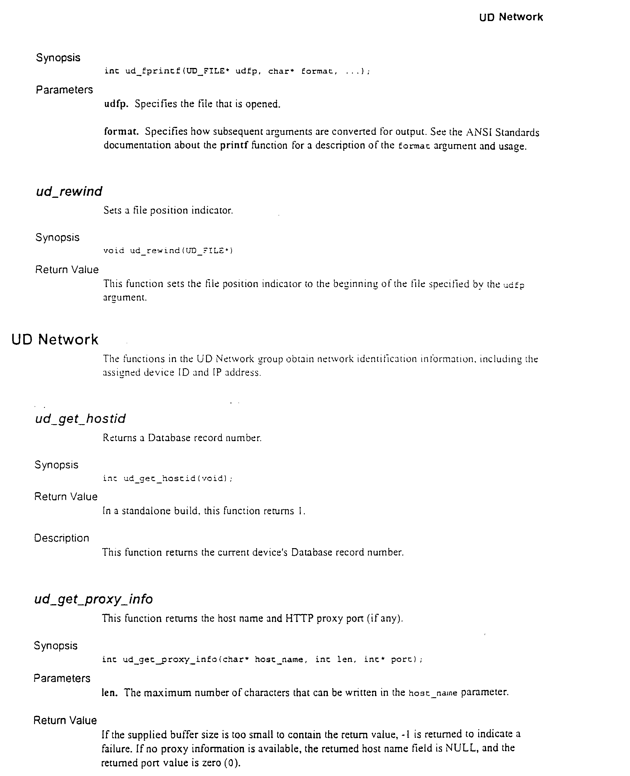


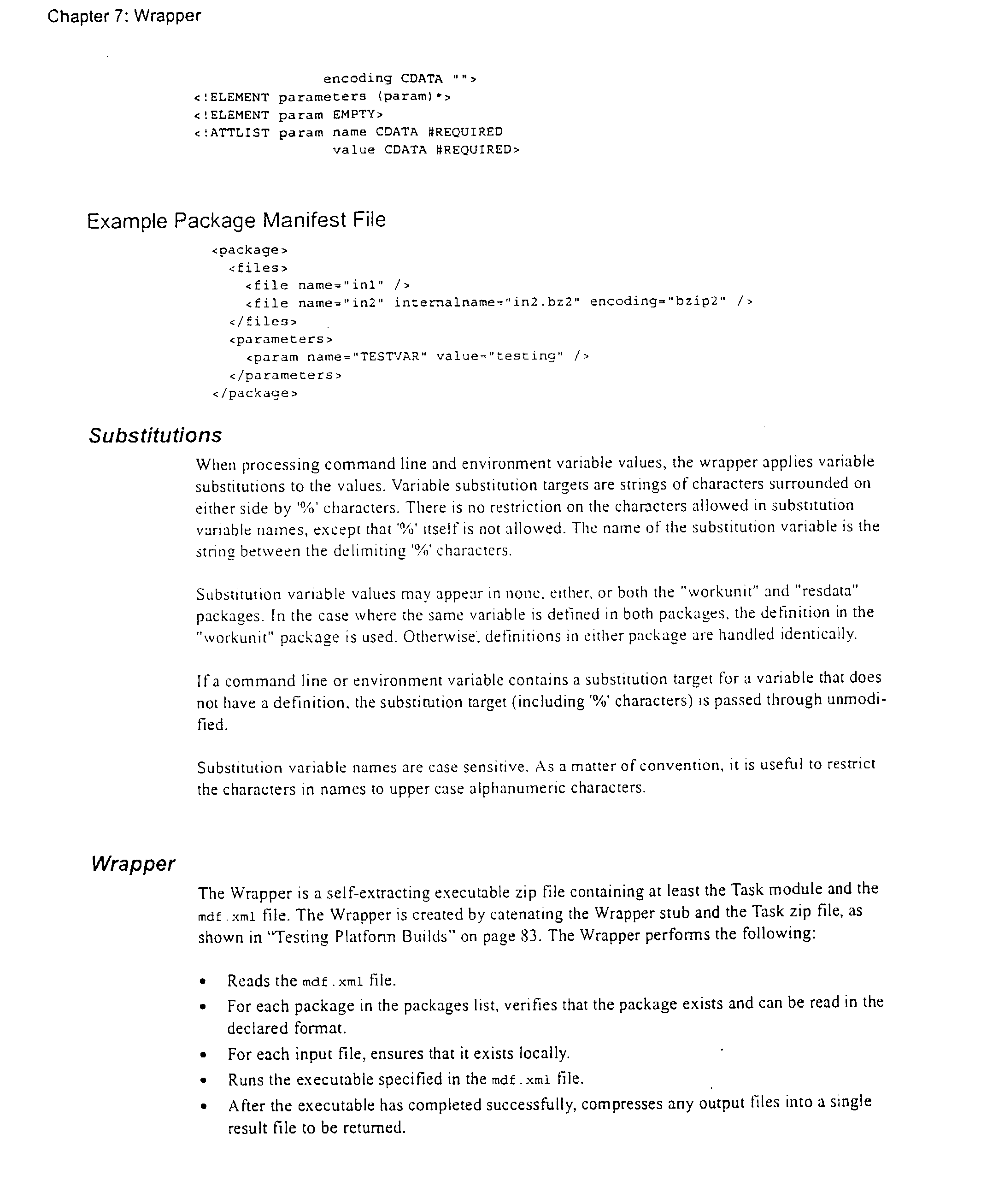


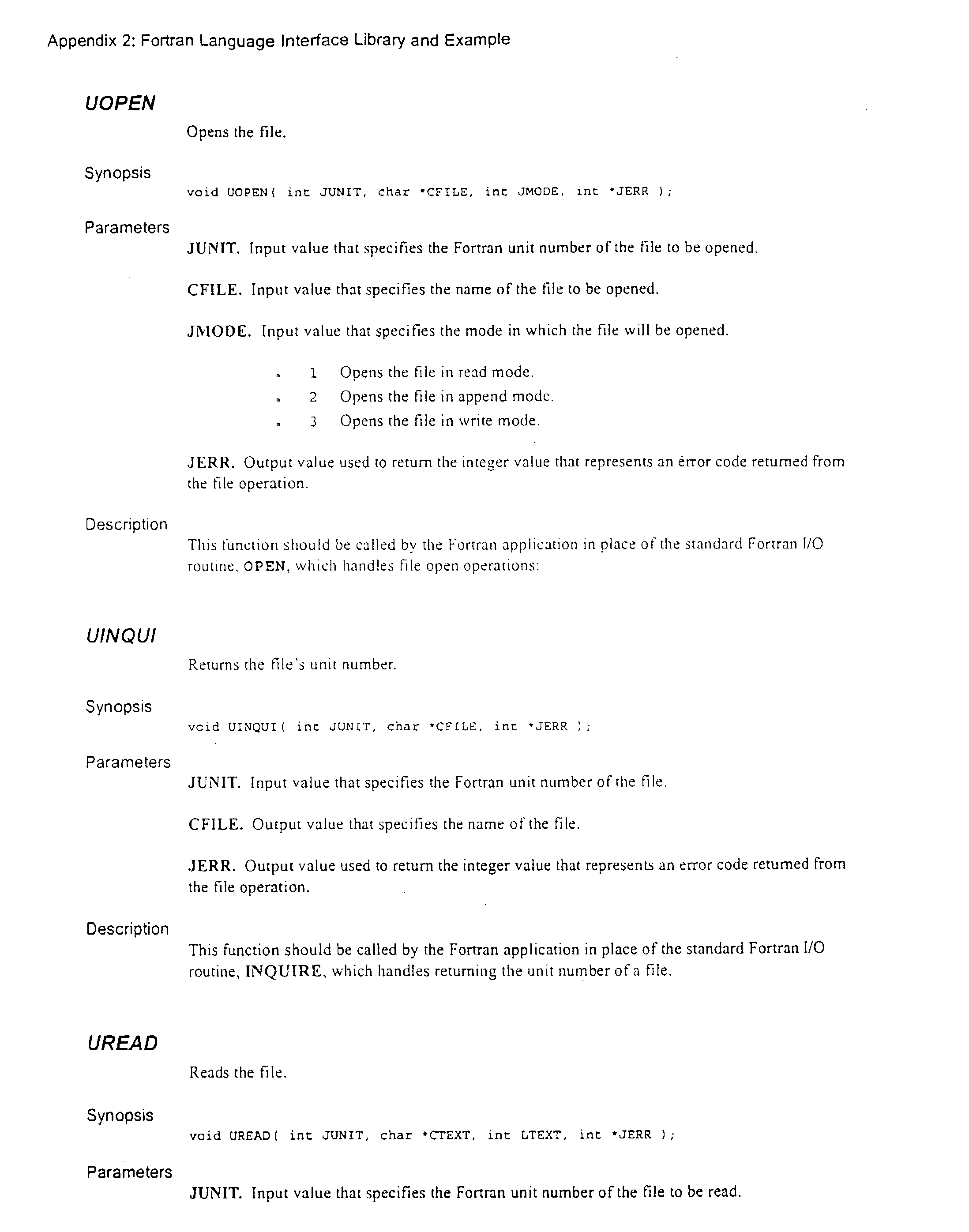


- Further modifications and alternative embodiments of this invention will be apparent to those skilled in the art in view of this description. It will be recognized, therefore, that the present invention is not limited by these example arrangements. Accordingly, this description is to be construed as illustrative only and is for the purpose of teaching those skilled in the art the manner of carrying out the invention. It is to be understood that the forms of the invention herein shown and described are to be taken as the presently preferred embodiments. Various changes may be made in the shape, size and arrangement of parts. For example, equivalent elements may be substituted for those illustrated and described herein, and certain features of the invention may be utilized independently of the use of other features, all as would be apparent to one skilled in the art after having the benefit of this description of the invention.
Claims (17)
Priority Applications (2)
| Application Number | Priority Date | Filing Date | Title |
|---|---|---|---|
| US10/402,331 US20040148336A1 (en) | 2000-03-30 | 2003-03-28 | Massively distributed processing system architecture, scheduling, unique device identification and associated methods |
| US11/773,929 US20110173247A1 (en) | 2000-03-30 | 2007-07-05 | Massively Distributed Processing System Architecture, Scheduling, Unique Device Identification and Associated Methods |
Applications Claiming Priority (11)
| Application Number | Priority Date | Filing Date | Title |
|---|---|---|---|
| US53942800A | 2000-03-30 | 2000-03-30 | |
| US53944800A | 2000-03-30 | 2000-03-30 | |
| US09/539,106 US6891802B1 (en) | 2000-03-30 | 2000-03-30 | Network site testing method and associated system |
| US60374000A | 2000-06-23 | 2000-06-23 | |
| US09/602,983 US6963897B1 (en) | 2000-03-30 | 2000-06-23 | Customer services and advertising based upon device attributes and associated distributed processing system |
| US09/648,832 US6847995B1 (en) | 2000-03-30 | 2000-08-25 | Security architecture for distributed processing systems and associated method |
| US09/794,969 US20010039497A1 (en) | 2000-03-30 | 2001-02-27 | System and method for monitizing network connected user bases utilizing distributed processing systems |
| US09/834,785 US8275827B2 (en) | 2000-03-30 | 2001-04-13 | Software-based network attached storage services hosted on massively distributed parallel computing networks |
| US36887102P | 2002-03-29 | 2002-03-29 | |
| US10/186,266 US7254607B2 (en) | 2000-03-30 | 2002-06-27 | Dynamic coordination and control of network connected devices for large-scale network site testing and associated architectures |
| US10/402,331 US20040148336A1 (en) | 2000-03-30 | 2003-03-28 | Massively distributed processing system architecture, scheduling, unique device identification and associated methods |
Related Parent Applications (9)
| Application Number | Title | Priority Date | Filing Date |
|---|---|---|---|
| US53944800A Continuation-In-Part | 2000-03-30 | 2000-03-30 | |
| US53942800A Continuation-In-Part | 2000-03-30 | 2000-03-30 | |
| US09/539,106 Continuation-In-Part US6891802B1 (en) | 2000-03-30 | 2000-03-30 | Network site testing method and associated system |
| US09/602,983 Continuation-In-Part US6963897B1 (en) | 2000-03-30 | 2000-06-23 | Customer services and advertising based upon device attributes and associated distributed processing system |
| US60374000A Continuation-In-Part | 2000-03-30 | 2000-06-23 | |
| US09/648,832 Continuation-In-Part US6847995B1 (en) | 2000-03-30 | 2000-08-25 | Security architecture for distributed processing systems and associated method |
| US09/794,969 Continuation-In-Part US20010039497A1 (en) | 2000-03-30 | 2001-02-27 | System and method for monitizing network connected user bases utilizing distributed processing systems |
| US09/834,785 Continuation-In-Part US8275827B2 (en) | 2000-03-30 | 2001-04-13 | Software-based network attached storage services hosted on massively distributed parallel computing networks |
| US10/186,266 Continuation-In-Part US7254607B2 (en) | 2000-03-30 | 2002-06-27 | Dynamic coordination and control of network connected devices for large-scale network site testing and associated architectures |
Related Child Applications (1)
| Application Number | Title | Priority Date | Filing Date |
|---|---|---|---|
| US11/773,929 Continuation US20110173247A1 (en) | 2000-03-30 | 2007-07-05 | Massively Distributed Processing System Architecture, Scheduling, Unique Device Identification and Associated Methods |
Publications (1)
| Publication Number | Publication Date |
|---|---|
| US20040148336A1 true US20040148336A1 (en) | 2004-07-29 |
Family
ID=46299097
Family Applications (1)
| Application Number | Title | Priority Date | Filing Date |
|---|---|---|---|
| US10/402,331 Abandoned US20040148336A1 (en) | 2000-03-30 | 2003-03-28 | Massively distributed processing system architecture, scheduling, unique device identification and associated methods |
Country Status (1)
| Country | Link |
|---|---|
| US (1) | US20040148336A1 (en) |
Cited By (47)
| Publication number | Priority date | Publication date | Assignee | Title |
|---|---|---|---|---|
| US20030093402A1 (en) * | 2001-10-18 | 2003-05-15 | Mitch Upton | System and method using a connector architecture for application integration |
| US20030204684A1 (en) * | 2002-04-25 | 2003-10-30 | Schulz Jurgen M. | Distributed caching mechanism for pending memory operations within a memory controller |
| US20040006663A1 (en) * | 2002-05-01 | 2004-01-08 | David Wiser | System and method for storing large messages |
| US20040006550A1 (en) * | 2002-05-02 | 2004-01-08 | Mitch Upton | System and method for enterprise application interactions |
| US20040010611A1 (en) * | 2002-05-01 | 2004-01-15 | David Wiser | Single servlets for B2B message routing |
| US20040015859A1 (en) * | 2002-05-02 | 2004-01-22 | Timothy Potter | Systems and methods for modular component deployment |
| US20040049481A1 (en) * | 2002-05-01 | 2004-03-11 | Mike Blevins | Systems and methods for business process plug-in development |
| US20040068728A1 (en) * | 2002-05-02 | 2004-04-08 | Mike Blevins | Systems and methods for collaborative business plug-ins |
| US20040078440A1 (en) * | 2002-05-01 | 2004-04-22 | Tim Potter | High availability event topic |
| US20040168153A1 (en) * | 2003-02-26 | 2004-08-26 | Bea Systems, Inc. | Systems and methods for dynamic component versioning |
| US20040230955A1 (en) * | 2003-02-26 | 2004-11-18 | Bea Systems, Inc. | System for multi-language debugging |
| US20040236780A1 (en) * | 2003-02-25 | 2004-11-25 | Michael Blevins | Systems and methods for client-side filtering of subscribed messages |
| US20050010902A1 (en) * | 2003-02-25 | 2005-01-13 | Bea Systems, Inc. | Systems and methods extending an existing programming language with constructs |
| US20050034104A1 (en) * | 2003-02-26 | 2005-02-10 | Bea Systems, Inc. | Method for multi-language debugging |
| US20050108682A1 (en) * | 2003-02-26 | 2005-05-19 | Bea Systems, Inc. | Systems for type-independent source code editing |
| US20050114771A1 (en) * | 2003-02-26 | 2005-05-26 | Bea Systems, Inc. | Methods for type-independent source code editing |
| US20050240863A1 (en) * | 2003-02-25 | 2005-10-27 | Olander Daryl B | System and method for structuring distributed applications |
| US20060281555A1 (en) * | 2004-12-30 | 2006-12-14 | Jason Kellerman And Marc Marin | Computer networked game system utilizing subscription based membership and alternative methods of entry |
| US20070050841A1 (en) * | 2005-08-25 | 2007-03-01 | International Business Machines Corporation | Apparatus and method for authenticating computed results in a public distributed computing environment |
| US20070118652A1 (en) * | 2005-10-28 | 2007-05-24 | International Business Machines Corporation | Bundling and sending work units to a server based on a weighted cost |
| US20080154851A1 (en) * | 2006-12-21 | 2008-06-26 | Canon Kabushiki Kaisha | Method and apparatus for sharing files over a network |
| US20080235317A1 (en) * | 2004-01-27 | 2008-09-25 | Tom Burgmans | System and Method For Providing an Extended Computing Capacity |
| US20090112758A1 (en) * | 2007-10-30 | 2009-04-30 | Michael Herzig | Systems and methods for measuring utilized generation of at-premise renewable power systems |
| US20090171855A1 (en) * | 2000-03-30 | 2009-07-02 | Hubbard Edward A | Monitizing Network Connected User Bases Utilizing Distributed Processing Systems |
| US20090199274A1 (en) * | 2008-02-01 | 2009-08-06 | Matthew Frazier | method and system for collaboration during an event |
| US7650592B2 (en) | 2003-03-01 | 2010-01-19 | Bea Systems, Inc. | Systems and methods for multi-view debugging environment |
| US7650276B2 (en) | 2003-02-26 | 2010-01-19 | Bea Systems, Inc. | System and method for dynamic data binding in distributed applications |
| US7676538B2 (en) | 2002-05-02 | 2010-03-09 | Bea Systems, Inc. | Systems and methods for application view transactions |
| US7707564B2 (en) | 2003-02-26 | 2010-04-27 | Bea Systems, Inc. | Systems and methods for creating network-based software services using source code annotations |
| US7840611B2 (en) | 2002-05-01 | 2010-11-23 | Oracle International Corporation | High availability for event forwarding |
| US20100312823A1 (en) * | 2009-06-04 | 2010-12-09 | Microsoft Corporation | Dedicated processor core request |
| US20110066544A1 (en) * | 2005-08-16 | 2011-03-17 | Hughes John M | Systems and methods for providing investment opportunities |
| US7953787B2 (en) | 2002-05-02 | 2011-05-31 | Oracle International Corporation | System and method for providing highly available processing of asynchronous requests using distributed request and response queues and a service processor |
| US8015572B2 (en) | 2002-02-22 | 2011-09-06 | Oracle International Corporation | Systems and methods for an extensible software proxy |
| WO2012000999A1 (en) | 2010-07-02 | 2012-01-05 | International Business Machines Corporation | Configuring a computer system for a software package installation |
| US20140139533A1 (en) * | 2012-11-21 | 2014-05-22 | Institute For Information Industry | Graphic processing unit virtual apparatus, graphic processing unit host apparatus, and graphic processing unit program processing methods thereof |
| CN103854168A (en) * | 2014-02-17 | 2014-06-11 | 湖南中烟工业有限责任公司 | Heterogeneous process to-do task centralized processing method and device |
| US9322951B2 (en) | 2007-02-12 | 2016-04-26 | Locus Energy, Inc. | Weather and satellite model for estimating solar irradiance |
| US9606168B2 (en) | 2007-02-12 | 2017-03-28 | Locus Energy, Inc. | Irradiance mapping leveraging a distributed network of solar photovoltaic systems |
| US9686122B2 (en) | 2010-05-10 | 2017-06-20 | Locus Energy, Inc. | Methods for orientation and tilt identification of photovoltaic systems and solar irradiance sensors |
| CN110503484A (en) * | 2019-08-27 | 2019-11-26 | 中国工商银行股份有限公司 | Electronic ticket data matching method and device based on distributed caching |
| US10508987B2 (en) | 2016-09-12 | 2019-12-17 | Also Energy, Inc. | System and method for remote calibration of irradiance sensors of a solar photovoltaic system |
| US10564315B2 (en) | 2010-05-10 | 2020-02-18 | Locus Energy, Inc. | Methods for location identification of renewable energy systems |
| US10956629B2 (en) | 2012-12-28 | 2021-03-23 | Locus Energy, Inc. | Estimation of soiling losses for photovoltaic systems from measured and modeled inputs |
| US10962576B2 (en) | 2012-12-28 | 2021-03-30 | Locus Energy, Inc. | Estimation of shading losses for photovoltaic systems from measured and modeled inputs |
| US11143680B2 (en) | 2012-12-28 | 2021-10-12 | Locus Energy, Inc. | Estimation of energy losses due to partial equipment failure for photovoltaic systems from measured and modeled inputs |
| US11403024B2 (en) * | 2019-08-28 | 2022-08-02 | Cohesity, Inc. | Efficient restoration of content |
Citations (49)
| Publication number | Priority date | Publication date | Assignee | Title |
|---|---|---|---|---|
| US4669730A (en) * | 1984-11-05 | 1987-06-02 | Small Maynard E | Automated sweepstakes-type game |
| US4815741A (en) * | 1984-11-05 | 1989-03-28 | Small Maynard E | Automated marketing and gaming systems |
| US5056019A (en) * | 1989-08-29 | 1991-10-08 | Citicorp Pos Information Servies, Inc. | Automated purchase reward accounting system and method |
| US5332218A (en) * | 1989-01-30 | 1994-07-26 | Lucey Trevor C | Automated golf sweepstakes game |
| US5402394A (en) * | 1991-12-04 | 1995-03-28 | Turski; Klaus | Process for generating a common time base for a system with distributed computing units |
| US5483444A (en) * | 1993-10-26 | 1996-01-09 | Radisson Hotels International, Inc. | System for awarding credits to persons who book travel-related reservations |
| US5598566A (en) * | 1990-01-30 | 1997-01-28 | Johnson Service Company | Networked facilities management system having a node configured with distributed load management software to manipulate loads controlled by other nodes |
| US5655081A (en) * | 1995-03-08 | 1997-08-05 | Bmc Software, Inc. | System for monitoring and managing computer resources and applications across a distributed computing environment using an intelligent autonomous agent architecture |
| US5703949A (en) * | 1994-04-28 | 1997-12-30 | Citibank, N.A. | Method for establishing secure communications among processing devices |
| US5740549A (en) * | 1995-06-12 | 1998-04-14 | Pointcast, Inc. | Information and advertising distribution system and method |
| US5768504A (en) * | 1995-06-30 | 1998-06-16 | International Business Machines Corporation | Method and apparatus for a system wide logan in a distributed computing environment |
| US5802062A (en) * | 1996-06-19 | 1998-09-01 | At&T Corp | Preventing conflicts in distributed systems |
| US5815793A (en) * | 1995-10-05 | 1998-09-29 | Microsoft Corporation | Parallel computer |
| US5826265A (en) * | 1996-12-06 | 1998-10-20 | International Business Machines Corporation | Data management system having shared libraries |
| US5842219A (en) * | 1996-03-14 | 1998-11-24 | International Business Machines Corporation | Method and system for providing a multiple property searching capability within an object-oriented distributed computing network |
| US5862325A (en) * | 1996-02-29 | 1999-01-19 | Intermind Corporation | Computer-based communication system and method using metadata defining a control structure |
| US5887143A (en) * | 1995-10-26 | 1999-03-23 | Hitachi, Ltd. | Apparatus and method for synchronizing execution of programs in a distributed real-time computing system |
| US5893075A (en) * | 1994-04-01 | 1999-04-06 | Plainfield Software | Interactive system and method for surveying and targeting customers |
| US5909540A (en) * | 1996-11-22 | 1999-06-01 | Mangosoft Corporation | System and method for providing highly available data storage using globally addressable memory |
| US5918229A (en) * | 1996-11-22 | 1999-06-29 | Mangosoft Corporation | Structured data storage using globally addressable memory |
| US5916024A (en) * | 1986-03-10 | 1999-06-29 | Response Reward Systems, L.C. | System and method of playing games and rewarding successful players |
| US5921865A (en) * | 1997-01-16 | 1999-07-13 | Lottotron, Inc. | Computerized lottery wagering system |
| US5937192A (en) * | 1996-01-16 | 1999-08-10 | British Telecommunications Public Limited Company | Compilation of computer program for execution on single compiling computer and for execution on multiple distributed computer system |
| US5958010A (en) * | 1997-03-20 | 1999-09-28 | Firstsense Software, Inc. | Systems and methods for monitoring distributed applications including an interface running in an operating system kernel |
| US5966451A (en) * | 1997-02-20 | 1999-10-12 | Kabushiki Kaisha Toshiba | Distributed network computing system, and data exchange apparatus and method and storage medium used in this system |
| US5964832A (en) * | 1997-04-18 | 1999-10-12 | Intel Corporation | Using networked remote computers to execute computer processing tasks at a predetermined time |
| US5970477A (en) * | 1996-07-15 | 1999-10-19 | Bellsouth Intellectual Property Management Corporation | Method and system for allocating costs in a distributed computing network |
| US5970469A (en) * | 1995-12-26 | 1999-10-19 | Supermarkets Online, Inc. | System and method for providing shopping aids and incentives to customers through a computer network |
| US5978594A (en) * | 1994-09-30 | 1999-11-02 | Bmc Software, Inc. | System for managing computer resources across a distributed computing environment by first reading discovery information about how to determine system resources presence |
| US5987506A (en) * | 1996-11-22 | 1999-11-16 | Mangosoft Corporation | Remote access and geographically distributed computers in a globally addressable storage environment |
| US6003065A (en) * | 1997-04-24 | 1999-12-14 | Sun Microsystems, Inc. | Method and system for distributed processing of applications on host and peripheral devices |
| US6009455A (en) * | 1998-04-20 | 1999-12-28 | Doyle; John F. | Distributed computation utilizing idle networked computers |
| US6014634A (en) * | 1995-12-26 | 2000-01-11 | Supermarkets Online, Inc. | System and method for providing shopping aids and incentives to customers through a computer network |
| US6024640A (en) * | 1995-06-30 | 2000-02-15 | Walker Asset Management Limited Partnership | Off-line remote lottery system |
| US6026474A (en) * | 1996-11-22 | 2000-02-15 | Mangosoft Corporation | Shared client-side web caching using globally addressable memory |
| US6052785A (en) * | 1997-11-21 | 2000-04-18 | International Business Machines Corporation | Multiple remote data access security mechanism for multitiered internet computer networks |
| US6058393A (en) * | 1996-02-23 | 2000-05-02 | International Business Machines Corporation | Dynamic connection to a remote tool in a distributed processing system environment used for debugging |
| US6061660A (en) * | 1997-10-20 | 2000-05-09 | York Eggleston | System and method for incentive programs and award fulfillment |
| US6070190A (en) * | 1998-05-11 | 2000-05-30 | International Business Machines Corporation | Client-based application availability and response monitoring and reporting for distributed computing environments |
| US6094654A (en) * | 1996-12-06 | 2000-07-25 | International Business Machines Corporation | Data management system for file and database management |
| US6112304A (en) * | 1997-08-27 | 2000-08-29 | Zipsoft, Inc. | Distributed computing architecture |
| US6112225A (en) * | 1998-03-30 | 2000-08-29 | International Business Machines Corporation | Task distribution processing system and the method for subscribing computers to perform computing tasks during idle time |
| US6112181A (en) * | 1997-11-06 | 2000-08-29 | Intertrust Technologies Corporation | Systems and methods for matching, selecting, narrowcasting, and/or classifying based on rights management and/or other information |
| US6148335A (en) * | 1997-11-25 | 2000-11-14 | International Business Machines Corporation | Performance/capacity management framework over many servers |
| US6151684A (en) * | 1997-03-28 | 2000-11-21 | Tandem Computers Incorporated | High availability access to input/output devices in a distributed system |
| US6374254B1 (en) * | 1999-06-30 | 2002-04-16 | International Business Machines Corporation | Scalable, distributed, asynchronous data collection mechanism |
| US6418462B1 (en) * | 1999-01-07 | 2002-07-09 | Yongyong Xu | Global sideband service distributed computing method |
| US6463457B1 (en) * | 1999-08-26 | 2002-10-08 | Parabon Computation, Inc. | System and method for the establishment and the utilization of networked idle computational processing power |
| US6675382B1 (en) * | 1999-06-14 | 2004-01-06 | Sun Microsystems, Inc. | Software packaging and distribution system |
-
2003
- 2003-03-28 US US10/402,331 patent/US20040148336A1/en not_active Abandoned
Patent Citations (52)
| Publication number | Priority date | Publication date | Assignee | Title |
|---|---|---|---|---|
| US4815741A (en) * | 1984-11-05 | 1989-03-28 | Small Maynard E | Automated marketing and gaming systems |
| US4669730A (en) * | 1984-11-05 | 1987-06-02 | Small Maynard E | Automated sweepstakes-type game |
| US5916024A (en) * | 1986-03-10 | 1999-06-29 | Response Reward Systems, L.C. | System and method of playing games and rewarding successful players |
| US5332218A (en) * | 1989-01-30 | 1994-07-26 | Lucey Trevor C | Automated golf sweepstakes game |
| US5056019A (en) * | 1989-08-29 | 1991-10-08 | Citicorp Pos Information Servies, Inc. | Automated purchase reward accounting system and method |
| US5884072A (en) * | 1990-01-30 | 1999-03-16 | Johnson Service Company | Networked facilities management system with updated data based on aging time |
| US5598566A (en) * | 1990-01-30 | 1997-01-28 | Johnson Service Company | Networked facilities management system having a node configured with distributed load management software to manipulate loads controlled by other nodes |
| US6115713A (en) * | 1990-01-30 | 2000-09-05 | Johnson Controls Technology Company | Networked facilities management system |
| US5402394A (en) * | 1991-12-04 | 1995-03-28 | Turski; Klaus | Process for generating a common time base for a system with distributed computing units |
| US5483444A (en) * | 1993-10-26 | 1996-01-09 | Radisson Hotels International, Inc. | System for awarding credits to persons who book travel-related reservations |
| US5893075A (en) * | 1994-04-01 | 1999-04-06 | Plainfield Software | Interactive system and method for surveying and targeting customers |
| US5703949A (en) * | 1994-04-28 | 1997-12-30 | Citibank, N.A. | Method for establishing secure communications among processing devices |
| US5978594A (en) * | 1994-09-30 | 1999-11-02 | Bmc Software, Inc. | System for managing computer resources across a distributed computing environment by first reading discovery information about how to determine system resources presence |
| US5655081A (en) * | 1995-03-08 | 1997-08-05 | Bmc Software, Inc. | System for monitoring and managing computer resources and applications across a distributed computing environment using an intelligent autonomous agent architecture |
| US5740549A (en) * | 1995-06-12 | 1998-04-14 | Pointcast, Inc. | Information and advertising distribution system and method |
| US5768504A (en) * | 1995-06-30 | 1998-06-16 | International Business Machines Corporation | Method and apparatus for a system wide logan in a distributed computing environment |
| US6024640A (en) * | 1995-06-30 | 2000-02-15 | Walker Asset Management Limited Partnership | Off-line remote lottery system |
| US5815793A (en) * | 1995-10-05 | 1998-09-29 | Microsoft Corporation | Parallel computer |
| US5887143A (en) * | 1995-10-26 | 1999-03-23 | Hitachi, Ltd. | Apparatus and method for synchronizing execution of programs in a distributed real-time computing system |
| US6014634A (en) * | 1995-12-26 | 2000-01-11 | Supermarkets Online, Inc. | System and method for providing shopping aids and incentives to customers through a computer network |
| US5970469A (en) * | 1995-12-26 | 1999-10-19 | Supermarkets Online, Inc. | System and method for providing shopping aids and incentives to customers through a computer network |
| US5937192A (en) * | 1996-01-16 | 1999-08-10 | British Telecommunications Public Limited Company | Compilation of computer program for execution on single compiling computer and for execution on multiple distributed computer system |
| US6058393A (en) * | 1996-02-23 | 2000-05-02 | International Business Machines Corporation | Dynamic connection to a remote tool in a distributed processing system environment used for debugging |
| US5862325A (en) * | 1996-02-29 | 1999-01-19 | Intermind Corporation | Computer-based communication system and method using metadata defining a control structure |
| US5842219A (en) * | 1996-03-14 | 1998-11-24 | International Business Machines Corporation | Method and system for providing a multiple property searching capability within an object-oriented distributed computing network |
| US5802062A (en) * | 1996-06-19 | 1998-09-01 | At&T Corp | Preventing conflicts in distributed systems |
| US5970477A (en) * | 1996-07-15 | 1999-10-19 | Bellsouth Intellectual Property Management Corporation | Method and system for allocating costs in a distributed computing network |
| US6026474A (en) * | 1996-11-22 | 2000-02-15 | Mangosoft Corporation | Shared client-side web caching using globally addressable memory |
| US6148377A (en) * | 1996-11-22 | 2000-11-14 | Mangosoft Corporation | Shared memory computer networks |
| US5987506A (en) * | 1996-11-22 | 1999-11-16 | Mangosoft Corporation | Remote access and geographically distributed computers in a globally addressable storage environment |
| US5918229A (en) * | 1996-11-22 | 1999-06-29 | Mangosoft Corporation | Structured data storage using globally addressable memory |
| US5909540A (en) * | 1996-11-22 | 1999-06-01 | Mangosoft Corporation | System and method for providing highly available data storage using globally addressable memory |
| US6094654A (en) * | 1996-12-06 | 2000-07-25 | International Business Machines Corporation | Data management system for file and database management |
| US5826265A (en) * | 1996-12-06 | 1998-10-20 | International Business Machines Corporation | Data management system having shared libraries |
| US5921865A (en) * | 1997-01-16 | 1999-07-13 | Lottotron, Inc. | Computerized lottery wagering system |
| US5966451A (en) * | 1997-02-20 | 1999-10-12 | Kabushiki Kaisha Toshiba | Distributed network computing system, and data exchange apparatus and method and storage medium used in this system |
| US5958010A (en) * | 1997-03-20 | 1999-09-28 | Firstsense Software, Inc. | Systems and methods for monitoring distributed applications including an interface running in an operating system kernel |
| US6151684A (en) * | 1997-03-28 | 2000-11-21 | Tandem Computers Incorporated | High availability access to input/output devices in a distributed system |
| US5964832A (en) * | 1997-04-18 | 1999-10-12 | Intel Corporation | Using networked remote computers to execute computer processing tasks at a predetermined time |
| US6003065A (en) * | 1997-04-24 | 1999-12-14 | Sun Microsystems, Inc. | Method and system for distributed processing of applications on host and peripheral devices |
| US6112304A (en) * | 1997-08-27 | 2000-08-29 | Zipsoft, Inc. | Distributed computing architecture |
| US6061660A (en) * | 1997-10-20 | 2000-05-09 | York Eggleston | System and method for incentive programs and award fulfillment |
| US6112181A (en) * | 1997-11-06 | 2000-08-29 | Intertrust Technologies Corporation | Systems and methods for matching, selecting, narrowcasting, and/or classifying based on rights management and/or other information |
| US6052785A (en) * | 1997-11-21 | 2000-04-18 | International Business Machines Corporation | Multiple remote data access security mechanism for multitiered internet computer networks |
| US6148335A (en) * | 1997-11-25 | 2000-11-14 | International Business Machines Corporation | Performance/capacity management framework over many servers |
| US6112225A (en) * | 1998-03-30 | 2000-08-29 | International Business Machines Corporation | Task distribution processing system and the method for subscribing computers to perform computing tasks during idle time |
| US6009455A (en) * | 1998-04-20 | 1999-12-28 | Doyle; John F. | Distributed computation utilizing idle networked computers |
| US6070190A (en) * | 1998-05-11 | 2000-05-30 | International Business Machines Corporation | Client-based application availability and response monitoring and reporting for distributed computing environments |
| US6418462B1 (en) * | 1999-01-07 | 2002-07-09 | Yongyong Xu | Global sideband service distributed computing method |
| US6675382B1 (en) * | 1999-06-14 | 2004-01-06 | Sun Microsystems, Inc. | Software packaging and distribution system |
| US6374254B1 (en) * | 1999-06-30 | 2002-04-16 | International Business Machines Corporation | Scalable, distributed, asynchronous data collection mechanism |
| US6463457B1 (en) * | 1999-08-26 | 2002-10-08 | Parabon Computation, Inc. | System and method for the establishment and the utilization of networked idle computational processing power |
Cited By (73)
| Publication number | Priority date | Publication date | Assignee | Title |
|---|---|---|---|---|
| US10269025B2 (en) * | 2000-03-30 | 2019-04-23 | Intellectual Ventures Ii Llc | Monetizing network connected user bases utilizing distributed processing systems |
| US20090171855A1 (en) * | 2000-03-30 | 2009-07-02 | Hubbard Edward A | Monitizing Network Connected User Bases Utilizing Distributed Processing Systems |
| US20030093403A1 (en) * | 2001-10-18 | 2003-05-15 | Mitch Upton | System and method for implementing an event adapter |
| US20030105884A1 (en) * | 2001-10-18 | 2003-06-05 | Mitch Upton | System and method for using Web services with an enterprise system |
| US7340714B2 (en) * | 2001-10-18 | 2008-03-04 | Bea Systems, Inc. | System and method for using web services with an enterprise system |
| US7721193B2 (en) | 2001-10-18 | 2010-05-18 | Bea Systems, Inc. | System and method for implementing a schema object model in application integration |
| US7831655B2 (en) | 2001-10-18 | 2010-11-09 | Bea Systems, Inc. | System and method for implementing a service adapter |
| US20030093402A1 (en) * | 2001-10-18 | 2003-05-15 | Mitch Upton | System and method using a connector architecture for application integration |
| US8015572B2 (en) | 2002-02-22 | 2011-09-06 | Oracle International Corporation | Systems and methods for an extensible software proxy |
| US8484664B2 (en) | 2002-02-22 | 2013-07-09 | Oracle International Corporation | Systems and methods for an extensible software proxy |
| US6959361B2 (en) * | 2002-04-25 | 2005-10-25 | Sun Microsystems, Inc. | Distributed caching mechanism for pending memory operations within a memory controller |
| US20030204684A1 (en) * | 2002-04-25 | 2003-10-30 | Schulz Jurgen M. | Distributed caching mechanism for pending memory operations within a memory controller |
| US20040010611A1 (en) * | 2002-05-01 | 2004-01-15 | David Wiser | Single servlets for B2B message routing |
| US20040006663A1 (en) * | 2002-05-01 | 2004-01-08 | David Wiser | System and method for storing large messages |
| US20070198467A1 (en) * | 2002-05-01 | 2007-08-23 | Bea Systems, Inc. | System and method for storing large messages |
| US20040049481A1 (en) * | 2002-05-01 | 2004-03-11 | Mike Blevins | Systems and methods for business process plug-in development |
| US20040078440A1 (en) * | 2002-05-01 | 2004-04-22 | Tim Potter | High availability event topic |
| US7840532B2 (en) | 2002-05-01 | 2010-11-23 | Oracle International Corporation | System and method for storing large messages |
| US8135772B2 (en) | 2002-05-01 | 2012-03-13 | Oracle International Corporation | Single servlets for B2B message routing |
| US7840611B2 (en) | 2002-05-01 | 2010-11-23 | Oracle International Corporation | High availability for event forwarding |
| US20040015859A1 (en) * | 2002-05-02 | 2004-01-22 | Timothy Potter | Systems and methods for modular component deployment |
| US20040006550A1 (en) * | 2002-05-02 | 2004-01-08 | Mitch Upton | System and method for enterprise application interactions |
| US7953787B2 (en) | 2002-05-02 | 2011-05-31 | Oracle International Corporation | System and method for providing highly available processing of asynchronous requests using distributed request and response queues and a service processor |
| US8046772B2 (en) | 2002-05-02 | 2011-10-25 | Oracle International Corporation | System and method for enterprise application interactions |
| US7676538B2 (en) | 2002-05-02 | 2010-03-09 | Bea Systems, Inc. | Systems and methods for application view transactions |
| US20040068728A1 (en) * | 2002-05-02 | 2004-04-08 | Mike Blevins | Systems and methods for collaborative business plug-ins |
| US7350184B2 (en) | 2002-05-02 | 2008-03-25 | Bea Systems, Inc. | System and method for enterprise application interactions |
| US20050240863A1 (en) * | 2003-02-25 | 2005-10-27 | Olander Daryl B | System and method for structuring distributed applications |
| US7293038B2 (en) | 2003-02-25 | 2007-11-06 | Bea Systems, Inc. | Systems and methods for client-side filtering of subscribed messages |
| US20040236780A1 (en) * | 2003-02-25 | 2004-11-25 | Michael Blevins | Systems and methods for client-side filtering of subscribed messages |
| US20050010902A1 (en) * | 2003-02-25 | 2005-01-13 | Bea Systems, Inc. | Systems and methods extending an existing programming language with constructs |
| US7844636B2 (en) | 2003-02-25 | 2010-11-30 | Oracle International Corporation | Systems and methods for client-side filtering of subscribed messages |
| US7774697B2 (en) | 2003-02-25 | 2010-08-10 | Bea Systems, Inc. | System and method for structuring distributed applications |
| US7752599B2 (en) | 2003-02-25 | 2010-07-06 | Bea Systems Inc. | Systems and methods extending an existing programming language with constructs |
| US20050034104A1 (en) * | 2003-02-26 | 2005-02-10 | Bea Systems, Inc. | Method for multi-language debugging |
| US7707564B2 (en) | 2003-02-26 | 2010-04-27 | Bea Systems, Inc. | Systems and methods for creating network-based software services using source code annotations |
| US7650276B2 (en) | 2003-02-26 | 2010-01-19 | Bea Systems, Inc. | System and method for dynamic data binding in distributed applications |
| US20040168153A1 (en) * | 2003-02-26 | 2004-08-26 | Bea Systems, Inc. | Systems and methods for dynamic component versioning |
| US20040230955A1 (en) * | 2003-02-26 | 2004-11-18 | Bea Systems, Inc. | System for multi-language debugging |
| US8032860B2 (en) | 2003-02-26 | 2011-10-04 | Oracle International Corporation | Methods for type-independent source code editing |
| US20050114771A1 (en) * | 2003-02-26 | 2005-05-26 | Bea Systems, Inc. | Methods for type-independent source code editing |
| US20050108682A1 (en) * | 2003-02-26 | 2005-05-19 | Bea Systems, Inc. | Systems for type-independent source code editing |
| US7650592B2 (en) | 2003-03-01 | 2010-01-19 | Bea Systems, Inc. | Systems and methods for multi-view debugging environment |
| US20080235317A1 (en) * | 2004-01-27 | 2008-09-25 | Tom Burgmans | System and Method For Providing an Extended Computing Capacity |
| US20060281555A1 (en) * | 2004-12-30 | 2006-12-14 | Jason Kellerman And Marc Marin | Computer networked game system utilizing subscription based membership and alternative methods of entry |
| US20110066544A1 (en) * | 2005-08-16 | 2011-03-17 | Hughes John M | Systems and methods for providing investment opportunities |
| US7827596B2 (en) * | 2005-08-25 | 2010-11-02 | International Business Machines Corporation | Authenticating computed results in a public distributed computing environment |
| US20070050841A1 (en) * | 2005-08-25 | 2007-03-01 | International Business Machines Corporation | Apparatus and method for authenticating computed results in a public distributed computing environment |
| US20070118652A1 (en) * | 2005-10-28 | 2007-05-24 | International Business Machines Corporation | Bundling and sending work units to a server based on a weighted cost |
| US7606906B2 (en) * | 2005-10-28 | 2009-10-20 | International Business Machines Corporation | Bundling and sending work units to a server based on a weighted cost |
| US20080154851A1 (en) * | 2006-12-21 | 2008-06-26 | Canon Kabushiki Kaisha | Method and apparatus for sharing files over a network |
| US9322951B2 (en) | 2007-02-12 | 2016-04-26 | Locus Energy, Inc. | Weather and satellite model for estimating solar irradiance |
| US10495786B2 (en) | 2007-02-12 | 2019-12-03 | Locus Energy, Inc. | Weather and satellite model for estimating solar irradiance |
| US9606168B2 (en) | 2007-02-12 | 2017-03-28 | Locus Energy, Inc. | Irradiance mapping leveraging a distributed network of solar photovoltaic systems |
| US20090112758A1 (en) * | 2007-10-30 | 2009-04-30 | Michael Herzig | Systems and methods for measuring utilized generation of at-premise renewable power systems |
| US7706990B2 (en) * | 2007-10-30 | 2010-04-27 | Michael Herzig | Systems and methods for measuring utilized generation of at-premise renewable power systems |
| US20090199274A1 (en) * | 2008-02-01 | 2009-08-06 | Matthew Frazier | method and system for collaboration during an event |
| US9106630B2 (en) * | 2008-02-01 | 2015-08-11 | Mandiant, Llc | Method and system for collaboration during an event |
| US7984122B2 (en) * | 2009-06-04 | 2011-07-19 | Microsoft Corporation | Dedicated processor core request |
| US20100312823A1 (en) * | 2009-06-04 | 2010-12-09 | Microsoft Corporation | Dedicated processor core request |
| US9686122B2 (en) | 2010-05-10 | 2017-06-20 | Locus Energy, Inc. | Methods for orientation and tilt identification of photovoltaic systems and solar irradiance sensors |
| US10564315B2 (en) | 2010-05-10 | 2020-02-18 | Locus Energy, Inc. | Methods for location identification of renewable energy systems |
| US10728083B2 (en) | 2010-05-10 | 2020-07-28 | Locus Energy, Inc. | Methods for orientation and tilt identification of photovoltaic systems and solar irradiance sensors |
| US8645672B2 (en) | 2010-07-02 | 2014-02-04 | International Business Machines Corporation | Configuring a computer system for a software package installation |
| WO2012000999A1 (en) | 2010-07-02 | 2012-01-05 | International Business Machines Corporation | Configuring a computer system for a software package installation |
| US20140139533A1 (en) * | 2012-11-21 | 2014-05-22 | Institute For Information Industry | Graphic processing unit virtual apparatus, graphic processing unit host apparatus, and graphic processing unit program processing methods thereof |
| US10956629B2 (en) | 2012-12-28 | 2021-03-23 | Locus Energy, Inc. | Estimation of soiling losses for photovoltaic systems from measured and modeled inputs |
| US10962576B2 (en) | 2012-12-28 | 2021-03-30 | Locus Energy, Inc. | Estimation of shading losses for photovoltaic systems from measured and modeled inputs |
| US11143680B2 (en) | 2012-12-28 | 2021-10-12 | Locus Energy, Inc. | Estimation of energy losses due to partial equipment failure for photovoltaic systems from measured and modeled inputs |
| CN103854168A (en) * | 2014-02-17 | 2014-06-11 | 湖南中烟工业有限责任公司 | Heterogeneous process to-do task centralized processing method and device |
| US10508987B2 (en) | 2016-09-12 | 2019-12-17 | Also Energy, Inc. | System and method for remote calibration of irradiance sensors of a solar photovoltaic system |
| CN110503484A (en) * | 2019-08-27 | 2019-11-26 | 中国工商银行股份有限公司 | Electronic ticket data matching method and device based on distributed caching |
| US11403024B2 (en) * | 2019-08-28 | 2022-08-02 | Cohesity, Inc. | Efficient restoration of content |
Similar Documents
| Publication | Publication Date | Title |
|---|---|---|
| US6847995B1 (en) | Security architecture for distributed processing systems and associated method | |
| US8249940B2 (en) | Capability based distributed processing | |
| US7039670B2 (en) | Massively distributed processing system with modular client agent and associated method | |
| US8275827B2 (en) | Software-based network attached storage services hosted on massively distributed parallel computing networks | |
| US7092985B2 (en) | Method of managing workloads and associated distributed processing system | |
| US20040148336A1 (en) | Massively distributed processing system architecture, scheduling, unique device identification and associated methods | |
| US6963897B1 (en) | Customer services and advertising based upon device attributes and associated distributed processing system | |
| US20110173247A1 (en) | Massively Distributed Processing System Architecture, Scheduling, Unique Device Identification and Associated Methods | |
| US7082474B1 (en) | Data sharing and file distribution method and associated distributed processing system | |
| US6891802B1 (en) | Network site testing method and associated system | |
| US6654783B1 (en) | Network site content indexing method and associated system | |
| US7003547B1 (en) | Distributed parallel processing system having capability-based incentives and associated method | |
| US8010703B2 (en) | Data conversion services and associated distributed processing system | |
| US20090222508A1 (en) | Network Site Testing | |
| US7254607B2 (en) | Dynamic coordination and control of network connected devices for large-scale network site testing and associated architectures | |
| US7020678B1 (en) | Machine generated sweepstakes entry model and associated distributed processing system | |
| USRE42153E1 (en) | Dynamic coordination and control of network connected devices for large-scale network site testing and associated architectures | |
| Sehgal et al. | Cloud computing | |
| US20090254998A1 (en) | Web-browser based grid computing system | |
| US20110185231A1 (en) | Software application testing | |
| Kenwood | A business case study of open source software | |
| US9406074B2 (en) | Funnel analysis of the adoption of an application | |
| AU2001264551A1 (en) | Massively distributed processing system and associated methods | |
| Cappello et al. | Market-based massively parallel internet computing | |
| Yang et al. | A fair, secure and trustworthy peer-to-peer based cycle-sharing system |
Legal Events
| Date | Code | Title | Description |
|---|---|---|---|
| AS | Assignment |
Owner name: UNIVA CORPORATION, ILLINOIS Free format text: ASSIGNMENT OF ASSIGNORS INTEREST;ASSIGNOR:UNITED DEVICES, INC.;REEL/FRAME:020353/0187 Effective date: 20070830 |
|
| STCB | Information on status: application discontinuation |
Free format text: ABANDONED -- FAILURE TO RESPOND TO AN OFFICE ACTION |
|
| AS | Assignment |
Owner name: UNIVA CORPORATION, ILLINOIS Free format text: CHANGE OF NAME;ASSIGNOR:UD LIQUIDATION, INC., F/K/A UNITED DEVICES, INC.;REEL/FRAME:020593/0650 Effective date: 20080227 |
|
| AS | Assignment |
Owner name: SQUARE 1 BANK, NORTH CAROLINA Free format text: SECURITY AGREEMENT;ASSIGNOR:UNIVA CORPORATION;REEL/FRAME:020666/0387 Effective date: 20071018 |
|
| AS | Assignment |
Owner name: UNIVA CORPORATION, ILLINOIS Free format text: CORRECTION TO THE NATURE OF CONVEYANCE FROM CHANGE OF NAME TO CORRECTIVE CONFIRMATORY ASSIGNMENT FOR ASSIGNMENT RECORDED ON 03/04/08 IN REEL NO. 020593 AND FRAME NO. 0650;ASSIGNOR:UD LIQUIDATION, INC. F/K/A UNITED DEVICES, INC.;REEL/FRAME:021976/0741 Effective date: 20080227 |
|
| AS | Assignment |
Owner name: JOSEPHYN TRANSFER AG LLC, DELAWARE Free format text: ASSIGNMENT OF ASSIGNORS INTEREST;ASSIGNOR:UNIVA CORPORATION;REEL/FRAME:027150/0562 Effective date: 20110912 |
|
| AS | Assignment |
Owner name: UNIVA CORPORATION, ILLINOIS Free format text: RELEASE BY SECURED PARTY;ASSIGNOR:SQUARE 1 BANK;REEL/FRAME:029241/0106 Effective date: 20121104 |