US20040096103A1 - Method of spatially filtering a digital image using chrominance information - Google Patents
Method of spatially filtering a digital image using chrominance information Download PDFInfo
- Publication number
- US20040096103A1 US20040096103A1 US10/294,860 US29486002A US2004096103A1 US 20040096103 A1 US20040096103 A1 US 20040096103A1 US 29486002 A US29486002 A US 29486002A US 2004096103 A1 US2004096103 A1 US 2004096103A1
- Authority
- US
- United States
- Prior art keywords
- signal
- image
- pedestal
- digital image
- control signal
- Prior art date
- Legal status (The legal status is an assumption and is not a legal conclusion. Google has not performed a legal analysis and makes no representation as to the accuracy of the status listed.)
- Granted
Links
- 238000000034 method Methods 0.000 title claims abstract description 62
- 238000001914 filtration Methods 0.000 title claims abstract description 11
- NJPPVKZQTLUDBO-UHFFFAOYSA-N novaluron Chemical group C1=C(Cl)C(OC(F)(F)C(OC(F)(F)F)F)=CC=C1NC(=O)NC(=O)C1=C(F)C=CC=C1F NJPPVKZQTLUDBO-UHFFFAOYSA-N 0.000 claims abstract description 109
- 238000012545 processing Methods 0.000 claims abstract description 20
- 230000006872 improvement Effects 0.000 claims description 4
- 230000006870 function Effects 0.000 description 57
- 241000023320 Luma <angiosperm> Species 0.000 description 56
- OSWPMRLSEDHDFF-UHFFFAOYSA-N methyl salicylate Chemical compound COC(=O)C1=CC=CC=C1O OSWPMRLSEDHDFF-UHFFFAOYSA-N 0.000 description 56
- 230000006835 compression Effects 0.000 description 13
- 238000007906 compression Methods 0.000 description 13
- 230000008569 process Effects 0.000 description 12
- 238000010586 diagram Methods 0.000 description 11
- 239000003623 enhancer Substances 0.000 description 8
- 230000001419 dependent effect Effects 0.000 description 7
- 230000000694 effects Effects 0.000 description 7
- 230000004048 modification Effects 0.000 description 7
- 238000012986 modification Methods 0.000 description 7
- 239000011159 matrix material Substances 0.000 description 6
- 238000006243 chemical reaction Methods 0.000 description 5
- 238000003384 imaging method Methods 0.000 description 5
- 230000009466 transformation Effects 0.000 description 5
- 239000003086 colorant Substances 0.000 description 4
- 238000013459 approach Methods 0.000 description 3
- 238000004590 computer program Methods 0.000 description 3
- 230000003287 optical effect Effects 0.000 description 3
- 230000007704 transition Effects 0.000 description 3
- 238000004458 analytical method Methods 0.000 description 2
- 238000004364 calculation method Methods 0.000 description 2
- 230000007935 neutral effect Effects 0.000 description 2
- 230000003044 adaptive effect Effects 0.000 description 1
- 238000003491 array Methods 0.000 description 1
- 230000008901 benefit Effects 0.000 description 1
- 230000007812 deficiency Effects 0.000 description 1
- 230000002708 enhancing effect Effects 0.000 description 1
- 238000009499 grossing Methods 0.000 description 1
- 238000005286 illumination Methods 0.000 description 1
- 230000002452 interceptive effect Effects 0.000 description 1
- 238000012804 iterative process Methods 0.000 description 1
- 238000012886 linear function Methods 0.000 description 1
- 239000000463 material Substances 0.000 description 1
- 238000004321 preservation Methods 0.000 description 1
- 230000009467 reduction Effects 0.000 description 1
- 238000005070 sampling Methods 0.000 description 1
- 238000004513 sizing Methods 0.000 description 1
- 239000007787 solid Substances 0.000 description 1
- 238000001228 spectrum Methods 0.000 description 1
Images


Classifications
-
- G06T5/75—
-
- G06T5/90—
-
- G—PHYSICS
- G06—COMPUTING; CALCULATING OR COUNTING
- G06T—IMAGE DATA PROCESSING OR GENERATION, IN GENERAL
- G06T2207/00—Indexing scheme for image analysis or image enhancement
- G06T2207/20—Special algorithmic details
- G06T2207/20016—Hierarchical, coarse-to-fine, multiscale or multiresolution image processing; Pyramid transform
-
- G—PHYSICS
- G06—COMPUTING; CALCULATING OR COUNTING
- G06T—IMAGE DATA PROCESSING OR GENERATION, IN GENERAL
- G06T2207/00—Indexing scheme for image analysis or image enhancement
- G06T2207/20—Special algorithmic details
- G06T2207/20048—Transform domain processing
- G06T2207/20064—Wavelet transform [DWT]
Definitions
- the present invention relates to an improved method of spatially filtering digital images.
- tone scale function there exist many processes for creating a tone scale function on an image dependent basis (e.g. see U.S. Pat. No. 5,471,987, issued Dec. 5, 1995 to Nakazawa et al.).
- Each of the conventional tone scale function processes examines certain statistical characteristics of the image under consideration in order to automatically generate the tone scale function.
- the tone scale function may be generated with manual interactive tools by a human operator.
- tone scale function After the tone scale function has been generated, there exists the question of how to apply the tone scale function to the digital image.
- the goal of dynamic range compression is to adjust the overall dynamic range of the image, rather than to affect the contrast of any given object in the image.
- tone scale function should be applied to an image in such a way as to minimize the effect to the scene texture.
- Lee describes yet another dynamic range compression method using a multiple resolution representation of an image.
- Lee describes a method of using wavelet filters to create a plurality of coarse signals and detail signals, modifying the detail signals in accordance with contrast gain signals created by detecting the edges of the coarse scale edges, and adding the modified detail signals to the coarse signals to obtain an output image.
- the high frequency (or edge or band pass) components of the multiple resolution representation are modified to affect the image dynamic range.
- the characteristics of the high frequency signals vary as a function of the level within the multiple image representation of the image. This variability requires a complicated parameter tuning in order to achieve optimal dynamic range compression without producing objectionable artifacts (such as the aforementioned overshoot and undershoot artifact) using a multiple image resolution representation of the image.
- Multiresolution, or pyramid methods as a means of representing images as a function of spatial resolution for image processing, has a long history.
- Burt and Adelson described a method of representing a digital image by a series of residual images and a base digital image in their journal article “The Laplacian Pyramid as a Compact Image Code” IEEE Transactions on Communications, Vol. Com-31, No. 4, April 1983.
- Burt et al. was designed for image compression applications and cannot be used for enhancing the tone scale of a digital image.
- the prior art methods of dynamic range compression realize that the characteristics of the filter should vary in accordance with the edges of the image. Dynamic range compression is generally applied to only the luminance channel of an image having a luminance channel and one or more chrominance channels. However, because dynamic range compression is generally applied to the luminance channel of a luminance-chrominance image representation, the edges are determined from only the luminance image channel. Thus, the prior art methods sometimes fail when the edges cannot adequately be determined by the luminance channel of an image alone.
- the need is met according to the present invention by providing a method of processing a color digital image having a luminance channel and one or more chrominance channels to improve the tone scale characteristics of the image that includes the steps of: producing a control signal from the one or more chrominance channels; generating a pedestal signal containing mainly low frequency modulation by filtering the luminance channel with a spatial filter, whereby the operation of the spatial filter is modulated by the control signal; and producing a texture signal by subtracting the pedestal signal from the luminance channel.
- FIG. 1 is a block diagram of a computer system suitable for practicing the present invention
- FIG. 2 is a block diagram of the digital image processor of FIG. 1 according to the present invention.
- FIG. 3 is a block diagram of the luminance enhancer shown in FIG. 2;
- FIG. 4 is a block diagram of the pedestal splitter shown in FIG. 3;
- FIG. 5 is a block diagram of a luma control signal generator shown in FIG. 4;
- FIG. 6 is a block diagram of the preferred pedestal splitter
- FIG. 7 is a block diagram of the pyramid constructor shown in FIG. 6;
- FIG. 8 is a block diagram of the pyramid level module shown in FIG. 7;
- FIG. 9 is a block diagram of one iteration of the pedestal reconstructor shown in FIG. 6;
- FIG. 10 is a block diagram of one iteration of an alternative pedestal reconstructor shown in FIG. 6;
- FIG. 11 is a block diagram of the luma control signal generator shown in FIGS. 9 and 10.
- the present invention may be implemented in computer hardware.
- a digital imaging system which includes an image capture device 10 , a digital image processor 20 , an image output device 30 , and a general control computer 40 .
- the system can include a display device 50 such as a computer console or paper printer.
- the system can also include an input control device 60 for an operator such as a keyboard and or mouse pointer.
- the present invention can be used on multiple capture devices 10 that produce digital images.
- FIG. 1 can represent a digital photofinishing system where the image capture device 10 is a conventional photographic film camera for capturing a scene on color negative or reversal film, and a film scanner device for scanning the developed image on the film and producing a digital image.
- the digital image processor 20 provides the means for processing the digital images to produce pleasing looking images on the intended output device or media.
- the present invention can be used with a variety of output devices 30 that can include, but are not limited to, a digital photographic printer and soft copy display.
- the digital image processor 20 can be used to process digital images to make adjustments for overall brightness, tone scale, image structure, etc. of digital images in a manner such that a pleasing looking image is produced by an image output device 30 .
- Those skilled in the art will recognize that the present invention is not limited to just these mentioned image processing functions.
- the general control computer 40 shown in FIG. 1 can store the present invention as a computer program stored in a computer readable storage medium, which may comprise, for example: magnetic storage media such as a magnetic disk (such as a floppy disk) or magnetic tape; optical storage media such as an optical disc, optical tape, or machine readable bar code; and solid state electronic storage devices such as random access memory (RAM), or read only memory (ROM).
- a computer readable storage medium which may comprise, for example: magnetic storage media such as a magnetic disk (such as a floppy disk) or magnetic tape; optical storage media such as an optical disc, optical tape, or machine readable bar code; and solid state electronic storage devices such as random access memory (RAM), or read only memory (ROM).
- RAM random access memory
- ROM read only memory
- the associated computer program implementation of the present invention may also be stored on any other physical device or medium employed to store a computer program indicated by offline memory device 70 .
- offline memory device 70 Before describing the present invention, it facilitates understanding to note that the present invention is
- the present invention can be implemented in a combination of software and/or hardware and is not limited to devices which are physically connected and/or located within the same physical location.
- One or more of the devices illustrated in FIG. 1 may be located remotely and may be connected via a wireless connection.
- a digital image is comprised of one or more digital image channels.
- Each digital image channel is comprised of a two-dimensional array of pixels.
- Each pixel value relates to the amount of light received by the imaging capture device corresponding to the physical region of pixel.
- a digital image will often consist of red, green, and blue digital image channels.
- Motion imaging applications can be thought of as a sequence of digital images.
- a digital image channel is described as a two dimensional array of pixel values arranged by rows and columns, those skilled in the art will recognize that the present invention can be applied to non rectilinear arrays with equal effect.
- tone scale functions There are many different types of tone scale functions that can be applied to digital images for enhancement purposes. Some digital images are derived from original scenes photographed that have a high dynamic range of intensities present. In general, it is difficult to make pleasing prints from these high dynamic range digital images since the range of pixel values is so large. For a typical high dynamic range digital image, the image content in the highlight regions (bright portions) and shadow regions (dark portions) will often be rendered without detail since photographic paper can only reproduce faithfully a limited range of intensities. Therefore, a compressive tone scale function, i.e. a tone scale function designed to compress, or reduce, the dynamic range of a digital image, can be applied to a high dynamic range digital image to reduce the numerical range of pixel values.
- a compressive tone scale function i.e. a tone scale function designed to compress, or reduce, the dynamic range of a digital image
- the preferred embodiment of the present invention uses a spatial filter to apply a tone scale function to a digital image.
- the spatial filter is used to separate an original digital image into first and second signals—a pedestal signal and a texture signal.
- the texture signal contains image content that relates to edges and fine spatial detail.
- a tone scale function is applied to the pedestal signal. Since the pedestal signal does not contain fine spatial detail, but rather low frequency smoothly varying regions and edges from illumination changes, the application of the tone scale function to the pedestal signal does not reduce the magnitude of the fine spatial detail.
- the fine spatial detail is preserved in the texture signal, which is recombined with the processed pedestal part.
- the resulting process achieves the goal of reducing the overall dynamic range of the image to be within the printable range for the photographic paper (or other output medium, such as a CRT monitor) but doesn't reduce the magnitude of fine detail in the processed image.
- the improvement of the present invention comprises employing one or more of the chrominance channels to separate the luminance channel into the first and second signals.
- the digital image processor 20 shown in FIG. 1 and programmed to perform the method of the present invention is illustrated in more detail in FIG. 2.
- An original digital image 101 can be received from the image capture device (shown in FIG. 1) in a variety of different color representations.
- the most typical implementation of the present invention receives the original digital image as a color digital image with red, green, and blue digital image channels.
- the pixel values of the original digital image are related to the log of the scene intensity and each pixel value of each color channel is represented as a 12-bit value.
- every 188 code values represents a doubling of scene intensity (i.e. a photographic stop).
- a first pixel having a value of 1688 represents a scene intensity that is twice as great as a second pixel having a value of 1500.
- the present invention can operate successfully with other encodings, although modification to equation constants and shapes of functions may be required.
- An LCC conversion module 210 receives the original digital image 101 and generates a luminance digital image 107 (containing luminance information in a single digital image channel) and a chrominance digital image 109 (containing the color information in two color-difference digital image channels).
- the luminance digital image 107 is input to the luminance enhancer 240 for the purpose of creating an enhanced luminance digital image 113 .
- the chrominance digital image 109 is input to the chroma control signal generator 112 for the purpose of creating a chroma control signal 114 , which will be used to modify the effect of a spatial filter 116 within the luminance enhancer 240 .
- the tone scale generator 230 inputs the original digital image 101 and analyzes the image, outputting a tone scale function 203 that is used by the luminance enhancer to improve the tone scale of the digital image.
- the chrominance digital image 109 and enhanced luminance digital image 113 are received by the RGB conversion module 220 which performs a color transformation and generates the enhanced digital image 102 (containing red, green, and blue digital image channels) which is in the same color representation as the original digital image 101 . Notice that the enhanced luminance digital image 113 is produced from the chroma control signal 114 , a spatial filter 116 , the luminance digital image 107 , and the tone scale function 203 .
- the LCC module 210 shown in FIG. 2 preferably employs a 3 element by 3 element matrix transformation to convert the red, green, and blue pixel values of the original digital image 101 into luminance and chrominance pixel values.
- R(x,y), G(x,y), and B(x,y) refer to the pixel values corresponding to the red, green, and blue digital image channels located at the x th row and y th column.
- L(x,y), GM(x,y), and ILL(x,y) refer to the transformed luminance, first chrominance, and second chrominance pixel values respectively of an LCC original digital image.
- the 3 element by 3 elements of the matrix transformation are described by (1).
- GM ( x,y ) ⁇ 0.25 R ( x,y )+0.50 G ( x,y ) ⁇ 0.25 B ( x,y )
- GM ( x,y ) ⁇ 0.250 R ( x,y )+0.500 G ( x,y ) ⁇ 0.250 B ( x,y )
- the collection of luminance pixel values is the single-channel luminance digital image.
- the chrominance digital image has two channels, the green-magenta channel (whose values are GM(x,y)) and the illuminant channel (whose values are ILL(x,y)).
- the luminance digital image is made up of luminance pixel values and the chrominance digital image is made up of chrominance pixel values.
- the RGB conversion module 220 shown in FIG. 2 employs a 3 element by 3 element matrix transformation to convert the luminance and chrominance pixel values into red, green, and blue pixel values by performing the inverse matrix operation to the LCC module 210 .
- the matrix elements of the RGB module are given by (3).
- R ( x,y ) L ( x,y ) ⁇ 0.666 GM ( x,y ) ⁇ ILL ( x,y )
- G ( x,y ) L ( x,y )+1.333 GM ( x,y )
- the spatial filter 116 of FIG. 2 is a digital convolution filter having fixed coefficients.
- the luminance enhancer 240 applies the spatial filter 116 to the luminance digital image 107 according to the chroma control signal 114 in such a manner that the effect of the filter's application is non-linear. That is, the coefficients of the spatial filter 116 remain fixed, yet the application of the filter is non-linear because of the chroma control signal 114 .
- the spatial filter 116 is a Gaussian lowpass filter.
- b(i,j) the Gaussian filter coefficient at the (i,j) th pixel
- ⁇ the standard deviation of the Gaussian filter
- ⁇ the constant approximately 3.14159265 . . .
- the filter coefficients are as follows:
- Gaussian lowpass filter is separable into a horizontal component and a vertical component, which reduces the computational complexity.
- the tone scale function generator 230 (shown in FIG. 2) preferably generates the tone scale function by an analysis of the original digital image 101 .
- the tone scale function generator 230 incorporates the method described by Lee et al. in U.S. Pat. No. 5,822,453 to calculate and output the tone scale function 203 .
- the present invention can also be used with tone scale functions that are not derived from an analysis of the original digital image 101 , i.e. scene independent tone scale functions.
- tone scale functions that are not derived from an analysis of the original digital image 101 , i.e. scene independent tone scale functions.
- This tone scale function achieves a dynamic range compression effect due the linear equation having a slope of less than 1.0.
- the luminance enhancer 240 is illustrated in more detail in FIG. 3.
- the luminance digital image 107 , the spatial filter 116 , and the chroma control signal 114 are input to the pedestal splitter 120 for producing a pedestal signal 122 .
- the pedestal signal 122 is essentially identical to the luminance digital image 107 , with the exception that image texture is removed (i.e. texture that would be damaged if affected by the tone scale function).
- the pedestal signal 122 is smooth with sharp transitions corresponding to large lighting edges (such as the transition from a bright sky to a backlit mountain, or the edge of a high contrast shadow) in the luminance digital image.
- the pedestal signal p(x,y) is made up of the same number of rows and columns of pixels as the luminance digital image 107 .
- the pedestal splitter 120 and the chroma control signal 114 will be described in greater detail hereinbelow.
- the pedestal signal and the luminance digital image are input to a texture generator 128 for producing a texture signal 130 .
- the texture signal contains the image texture whose magnitude will be unaffected by the tone scale function.
- the texture generator 128 generates the texture signal 130 according to the following equation:
- L(x,y) represents the value of the pixel of the luminance digital image at the (x,y) location.
- p(x,y) represents the value of the pedestal signal at the (x,y) location.
- t(x,y) represents the value of the texture signal at the (x,y) location.
- the pedestal signal is input to the tone scale function applicator 124 , which produces the modified pedestal signal pm(x,y).
- the tone scale function applicator 124 produces the modified pedestal signal 126 according to the equation:
- pm(x,y) represents the value of the (x,y) the pixel of the modified pedestal signal pm(x,y).
- T[x] represents the value of the tone scale function 203 for an input value of x.
- the tone scale applicator 124 simply applies a look-up-table (LUT) to the pedestal signal, producing the modified pedestal signal 126 .
- LUT look-up-table
- the modified pedestal signal 126 and the texture signal 130 are then added by an adder 132 , producing the enhanced luminance digital image 113 .
- the adder 132 generates the enhanced luminance digital image simply by summing the pixel values of the texture signal and the modified pedestal signal 126 , according to the equation:
- Le(x,y) represents the value of the pixel of the enhanced luminance digital image 113 at the (x,y) location.
- pm(x,y) represents the value of the (x,y) the pixel of the modified pedestal signal 126 pm(x,y).
- t(x,y) represents the value of the (x,y) the pixel of the texture signal 130 t(x,y).
- the chroma control signal generator 112 receives the input of the chrominance digital image 109 and outputs the chroma control signal 114 .
- the chroma control signal 114 is then used by the luminance enhancer, as shown by FIG. 3, in the creation of the pedestal signal 122 .
- the pedestal signal is conceptually smooth, except at locations of lighting edges.
- the pedestal splitter 114 is essentially an edge-preserving smoothing filter, which smoothes detail but preserves edges. In practice, however, it can be very difficult to distinguish between “edges” and “detail.”
- prior art methods employ a means by which the filtering on the luminance digital image varies as a function of a local gradient measure.
- the chroma control signal 114 aids the pedestal splitter 120 in order that the pedestal splitter 120 can distinguish between “edge” regions and “detail” regions with greater accuracy and robustness than when not using any information from the chrominance digital image 109 of FIG. 2.
- the pedestal splitter 120 of FIG. 3 uses color information, that when combined with the edge-preserving filtering on the luminance digital image alone, provides for a more robust classification of “edge” regions and “detail” regions, resulting in a superior enhanced digital image, specifically having a uniform look to the sky regions.
- the chroma control signal generator 112 of FIG. 2 generates the chroma control signal as follows. Recall that the chrominance digital image is made of chrominance channels, specifically the GM and the ILL channels.
- the chroma control signal is made by simultaneously considering M ⁇ M windows of the chrominance channels. For each pixel location of the chroma control signal, corresponding windows of the chrominance channels are considered.
- the gradient threshold value is determined as a function of the distance between values from the chrominance channels to a target color as follows.
- a color weight is determined for each pixel location within the window. Preferably, the color weight is such that chrominance values having a smaller distance to a target color (e.g.
- the color weight is assigned using a 2 dimensional look-up-table (one dimension is GM, and the other dimension is ILL), originally generated by evaluating a two dimensional Gaussian function, as described in U.S. Pat. No. 6,438,264.
- the color weight of the window is preferably the maximum of the color weights of the pixels belonging to the window.
- a chroma edge value for each window is found by considering the variance, or some other measure of the spread of different colors represented within the window and multiplying that by the window's color weight.
- the chroma edge value is preferably found as follows:
- Ce is the chroma edge value for a pixel having an associated M ⁇ M window of pixels
- Cw is the color weight of the M ⁇ M window
- ⁇ v is a measure of the variance of the chrominance values contained in the M ⁇ M window.
- GMn represents the m th green-magenta chrominance value of the M ⁇ M values within the M ⁇ M window.
- ILLn represents the m th illuminant chrominance value of the M ⁇ M values within the M ⁇ M window.
- M 2.
- a is an arbitrary constant, preferably 1.5
- b is an arbitrary constant, preferably 175
- d is an arbitrary constant, preferably 150.
- Cv is the chroma control value for a particular M ⁇ M window.
- the chroma control value will be high when the corresponding windows of the chrominance channels contain at least one blue pixel, and the window has a high variance of color.
- the chroma control value will be zero if the window contains no blue pixels. Additionally, the chroma control value will be zero if the pixels in the window have identical chrominance channel values.
- the pedestal splitter 120 shown in FIG. 3, is shown in more detail in FIG. 4.
- the luminance digital image 107 is input to a frequency splitter 134 , along with the spatial filter 116 .
- a lowpass signal 136 is created by convolving the luminance digital image 107 with the spatial filter 116 . Convolution is well known in the art.
- a highpass signal 138 is also produced by the frequency splitter by performing a pixel by pixel difference operation, wherein the lowpass signal is subtracted from the luminance digital image 107 .
- L(x,y) represents the value of the pixel of the luminance digital image at the (x,y) location.
- l(x,y) represents the value of the lowpass signal at the (x,y) location.
- h(x,y) represents the value of the highpass signal at the (x,y) location.
- the lowpass signal 136 and the chroma control signal 114 are input to the luma control signal generator 140 for generating the luma control signal 142 .
- the luminance digital image or a spatial filtered version of the luminance digital image or the green channel from the original digital image could be input to the luma control signal generator 140 in place of the lowpass signal 136 .
- the luma control signal 142 controls the effect of the spatial filter on the luminance digital image 107 .
- the luma control signal is created as shown in FIG. 5.
- the non-directional gradient G of the lowpass signal 136 is calculated by the gradient calculator 150 and output as the gradient signal 152 . This calculation is performed by first calculating vertical and horizontal gradients with a spatial filter called a gradient filter.
- the preferred embodiment of the present invention uses two one-dimensional Prewitt spatial filters to generate a vertical and a horizontal gradient value for each input pixel value given by equation (12) and (13) - 1 0 1 - 1 0 1 - 1 0 1 ( 12 ) - 1 - 1 - 1 0 0 0 1 1 1 ( 13 )
- the non-directional gradient signal 152 is the square root of the sum of the squares of these two gradients.
- the control signal applicator 154 inputs both the gradient signal 152 and the chroma control signal 114 and produces the luma control signal 142 .
- the values of the luma control signal 142 are in the range of 0 to 1, and are found by applying a gradient threshold that is dependent on the value of the chroma control signal 114 to the gradient signal 152 .
- the luma control signal 142 has a value of 1.0 corresponding to “edge” regions and a value of 0.0 corresponding to “detail” regions in the original digital image and intermediate values for regions that are not easily classified as “edge” or “detail”.
- classification of “edge” and “detail” regions in the luma control signal 114 is dependent on the chrominance channels.
- a classification of “edge” can be attained more easily (i.e. the gradient signal requirement is lowered) in the luma control signal when the chrominance channels meet certain requirements (e.g. at least one blue pixel and a large variety of colors are represented).
- Lc(x,y) is the value of the luma control signal 142 at the (x,y) location.
- G(x,y) is the value of the gradient signal 152 at the (x,y) location.
- p is a location-dependent threshold that is dependent on the value of the chroma control signal 114 and is preferably:
- f is an arbitrary constant, preferably 68.
- the chroma control signal 114 is derived from the chrominance channels, and the luma control signal is derived from the chroma control signal 114 . Therefore, the luma control signal is derived in part from the chroma control signal 114 .
- the highpass signal and the luma control signal 142 are input to a multiplier 144 for generating a modified highpass signal 146 by performing a pixel-by-pixel multiplication, according to the equation:
- hm(x,y) represents the value of the modified highpass signal 146 at the (x,y) location.
- lc(x,y) represents the value of the luma control signal 142 at the (x,y) location.
- h(x,y) represents the value of the highpass signal 138 at the (x,y) location.
- the pedestal signal 122 is produced by an adder 132 that inputs the modified highpass signal 146 and the lowpass signal 136 and adds these input signals according to (x,y) location.
- the chroma control signal 114 of FIG. 2 has a large value for image pixels corresponding to windows containing blue pixels and a high variance of color.
- a high chroma control value results in a more inclusive requirement for luminance gradient to have a value of 1 (i.e. be classified as an edge) in the luma control signal 142 of FIG. 4.
- the modified highpass signal 146 value is then similar to the highpass signal 138 value, and the pedestal signal 122 is then similar in value to the luminance digital image 107 , while the texture signal 130 value is zero.
- the pedestal signal 122 of FIG. 3 is then modified by the tone scale function applicator 124 according to the tone scale function 203 , compressing the edge.
- the chrominance channels of the original digital image are used to locally vary a threshold that is applied to the gradient of the luminance digital image to distinguish “edge” (high gradient) and “detail” (low gradient) regions.
- the highpass information of the edge regions is affected by the tone scale function, resulting in an image having compressed dynamic range.
- the highpass information of the detail regions is not affected by the tone scale function, so the highpass detail is preserved in these regions.
- using the chrominance digital image portion of the original digital image improves the method of application of a tone scale function to a digital image.
- the discussion to this point described the generic method of the present invention. In the discussion to follow, a specific embodiment of the method will be described.
- the preferred embodiment of the pedestal splitter 120 is shown in FIG. 6, where a pyramid representation of the image is used so that the produced pedestal signal 122 is a result of removing texture information at many different scales.
- the luminance digital image 107 is input to the pyramid constructor 156 , which outputs an image pyramid representation 108 .
- the image pyramid representation 108 contains all of the information that is contained in the luminance digital image 107 , and the image pyramid representation 108 can be easily converted back to the luminance digital image 107 .
- the image pyramid representation 108 includes several image signals.
- the image pyramid representation 108 includes the base digital image, which is essentially a smaller (fewer pixels) version of the luminance digital image 107 , and residual images, which contain highpass information from different scales (i.e. the residual images contain bandpass information).
- the pyramid representation 108 is input to the pedestal reconstructor 158 , which combines the image signals of the image pyramid representation 108 in such a manner that the texture information is removed, forming the pedestal signal 122 .
- the pyramid constructor 156 is illustrated in more detail in FIG. 7.
- a digital image channel 164 is input to the pyramid level module 115 1 .
- the pyramid level module 115 produces a first base digital image 103 1 and residual digital image 104 1 .
- the residual digital image has the same number of rows and columns of pixels as the digital image channel 164 .
- the base image channel has 1/Q the number of rows and 1/Q the number of columns of pixels of the digital image channel 164 .
- Q 2.
- the base image channel 103 1 produced by the first pyramid level module 115 1 is input to the second pyramid level module 115 2 , producing a second base image channel 103 2 and a second residual image 104 2 .
- the second base image channel 103 2 has 1/Q 2 the number of rows and 1/Q 2 the number of columns of the digital image channel 164 , while the second residual digital image 104 2 has the same number of rows and columns of pixels as the first base image channel 103 1 .
- the process iteratively continues N times, when the final pyramid level module 115 N inputs the N ⁇ 1 th base image channel and produces the N th base image channel 103 N and the N residual digital image 104 N .
- the base image channel is a digital image channel, so the pyramid level module always inputs a digital image channel.
- the digital image channel input to the first pyramid level module can be considered the 0 th base image channel.
- FIG. 8 fully illustrates the pyramid level module 115 .
- the nth base image channel 103 n is input to a block averager 170 for producing the n+1 th base image channel 103 n+1 .
- the block averager 170 produces a new digital image channel whereby each pixel value of the new digital image channel is formed by determining the mean pixel value of corresponding Q ⁇ Q non-overlapping blocks in the n th base image channel 103 n .
- This technique for reducing the resolution of an image by an integer factor is well known in the art of image processing, as is applying a lowpass convolution filter followed by a sampling operation.
- the output of the block averager is the base image channel n+1 103 n+1 , which is also an output of the pyramid level module 115 .
- highpass information is discarded.
- the residual signal contains the discarded highpass information such that the base image channel 103 n+1 and the residual image channel 104 n+1 can be combined to form the base image channel 103 n .
- the base image channel 103 n+1 output from the block averager 170 is passed to an interpolator 172 for interpolation by the factor Q.
- the interpolator 172 performs a standard bilinear interpolation by a factor of two.
- the preferred bilinear interpolation is such that the phase of the interpolated image is that same as that of the base image channel 103 n .
- Such bilinear interpolation is commonly known and practiced in the art of image processing and will not be further discussed.
- the output of the interpolator 172 is the interpolated base image channel 174 .
- the interpolated base image channel 174 is input to the differencer 176 .
- the differencer 176 calculates the residual image channel 104 n+1 by subtracting the interpolated base image channel 174 from the base image channel 103 n , according to the equation:
- r(x,y) represents the value of the pixel of the residual image channel 104 n+1 at the (x,y) location.
- b(x,y) represents the value of the nth base image channel 103 n at the (x,y) location.
- bi(x,y) represents the value of the interpolated base image channel 174 at the (x,y) location.
- the base digital image 103 n can be formed from the base digital image 103 n+1 and the residual digital image 104 n+1 through a reconstruction process.
- the process includes the steps of interpolating the base digital image 103 n+1 , then adding the residual digital image 104 n+1 .
- the digital image channel 164 shown in FIG. 7 can be represented as a collection of residual digital images 104 1-N and one base digital image 103 N .
- the perfect reconstruction of the digital image channel 164 is an iterative process where one base digital image and the corresponding residual image are used to create a higher resolution base digital image, which in turn is used with the next residual digital image to create an even higher resolution base digital image.
- N 8 pyramid levels are used in the pyramid representation. Perfect reconstruction of an image pyramid is well known.
- the pedestal reconstructor 158 generates a pedestal signal 122 by performing the reconstruction process with the modification that at each pyramid level, image texture is removed, or left out of the reconstruction.
- the iterative pedestal reconstructor inputs the pedestal signal 122 n , which is the pedestal signal at resolution level n.
- the pedestal signal N 122 N is set equal to the lowest resolution base image channel 103 N .
- the pedestal reconstruction module inputs the pedestal signal n 122 n and outputs a higher resolution pedestal signal 122 n ⁇ 1 .
- the pedestal signal 122 of FIG. 6 is the highest resolution (final) pedestal signal 122 0 .
- the pedestal signal n 122 n is input to a frequency splitter 134 .
- the frequency splitter 134 applies a spatial filter 116 to the pedestal signal, generating the lowpass signal 136 .
- the spatial filter 116 is lowpass in nature, attenuating any high frequency content in the pedestal signal 122 n .
- the frequency splitter 134 also outputs a highpass signal 138 in the manner previously described (similar to Equation 11).
- the highpass signal 138 is calculated as the difference between the pedestal signal n 122 n and the lowpass signal 136 .
- the lowpass signal 136 and the chroma control signal 114 are input to the luma control signal generator 180 for generating the luma control signal 182 .
- the operation of the luma control signal generator 180 will be described in more detail hereinbelow.
- the luma control signal 182 has a value near 1.0 corresponding to “edge” regions in luminance digital image 107 , and a value near 0 for other regions, with intermediate values.
- the multiplier 144 multiplies the highpass signal 138 and the luma control signal 182 , forming the modified highpass signal 146 .
- the modified highpass signal is then added by an adder 132 to the lowpass signal 136 , resulting in a signal that has the same pixel values as the pedestal signal 122 n in edge regions and that is smoothed in non-edge regions.
- the signal output from the adder 132 1 is interpolated by a factor Q by the interpolator 172 and then added by a second adder 132 2 to the residual image channel 104 n , resulting in the next higher resolution pedestal signal 122 n ⁇ 1 .
- FIG. 10 An alternative of one iteration of the pedestal reconstructor 158 of FIG. 6 is shown in greater detail in FIG. 10.
- the pedestal signal n 122 n is input to a frequency splitter 134 .
- the frequency splitter 134 applies a spatial filter 116 to the pedestal signal, generating the lowpass signal 136 .
- the spatial filter 116 is lowpass in nature, attenuating any high frequency content in the pedestal signal 122 n .
- the lowpass signal 136 and the chroma control signal 114 are input to the luma control signal generator 180 for generating the luma control signal 182 , in identical fashion as in regard to FIG. 9.
- the luma control signal 182 has a value near 1.0 corresponding to “edge” regions in luminance digital image 107 , and a value near 0 for other regions, with intermediate values.
- the luma control signal 182 is interpolated by a factor Q by an interpolator 172 , and multiplied by the residual image channel 104 n by a multiplier 144 , resulting in a signal that is zero in non-edge regions and maintains the values of the residual image channel 104 n in edge regions.
- the resulting signal is added with an adder 132 to the signal resulting from interpolating with an interpolator 172 the pedestal signal n, forming the pedestal signal 122 n ⁇ 1 .
- the pedestal signal 122 n ⁇ 1 is simply an interpolated version of the pedestal signal n, with the addition of residual image channel 104 n content in edge regions.
- FIGS. 9 and 10 illustrate two different iterative pedestal level reconstructors 158 for creating a higher resolution pedestal signal 122 from a starting pedestal signal.
- a pedestal signal 122 can be generated from the pyramid image representation 108 of FIG. 6.
- the pyramid image representation 108 has 8 levels.
- the reconstructor 158 shown in FIG. 9 is used to generate pedestal signals 122 7 to 122 4
- the reconstructor 158 shown in FIG. 10 is used to generate the remaining pedestal signals, including the final pedestal signal 122 output from the pedestal splitter 120 shown in FIG. 3.
- FIG. 11 illustrates the luma control signal generator 180 that is used to create the luma control signal 182 for use in generating the pedestal signal when reconstructing an image pyramid representation, as shown in FIGS. 9 and 10.
- the luma control signal generator 180 operates at each pyramid level in a very similar fashion to the luma control signal generator 140 that is used to create the pedestal signal 122 already described in regard to FIG. 5.
- a luma control signal 182 n is generated for each of the resolution levels during the pedestal reconstruction.
- the non-directional gradient G of the lowpass signal 136 n at resolution level n is calculated by the gradient calculator 150 and output as the gradient signal 152 . This calculation has already been described.
- the control signal applicator 154 inputs the gradient signal 152 the chroma control signal 114 n , and optionally the luma control signal 182 n+1 (the luma control signal previously calculated from the previous lower resolution) and produces the luma control signal 182 n .
- the values of the luma control signal 182 n are in the range of 0 to 1, and are found by applying a gradient threshold that is dependent on both the value of the chroma control signal 114 n and the luma control signal 182 n+1 to the gradient signal 152 .
- the luma control signal 182 n has a value of 1.0 corresponding to “edge” regions and a value of 0.0 corresponding to “detail” regions in the original digital image and intermediate values for regions that are not easily classified as “edge” or “detail”.
- a classification of “edge” can be attained more easily (i.e. the gradient signal requirement is lowered) in the luma control signal when the chrominance channels meet certain requirements (e.g. at least one blue pixel and a large variety of colors are represented.)
- the classification of “edge” is more difficult to attain (i.e.
- Lc(x,y) is the value of the luma control signal 182 at the (x,y) location
- G(x,y) is the value of the gradient signal 152 at the (x,y) location
- f is an arbitrary constant, preferably 68;
- h is an arbitrary constant, preferably 1.4;
- g is an arbitrary constant, preferably 0.4;
- Lo(xx,yy) is the value of the luma control signal n+1 at the location (xx,yy) that corresponds to the location (x,y) in the current resolution level n.
- the chroma control signal 114 is derived from the chrominance channels using an appropriate value of M (window size) such that the chroma control signal has an appropriate number of pixels.
- the luma control signal is derived from the chroma control signal 114 . Therefore, the luma control signal is derived in part from the chroma control signal 114 .
- the luma control signal 182 n also has a dependence on a previously calculated low resolution version of the luma control signal 182 n+1 .
- the luma control signal 182 n could be derived in part from any of the lower resolution versions of the luma control signal.
- the luma control signal 182 n could also be derived from a chroma control signal at any level of resolution with appropriate re-sizing.
- the present invention can be employed with any number of pyramid levels. Noise in images is generally a function of spatial resolution and is also more objectionable for the higher spatial resolution pyramid levels.
- the optimal number of pyramid levels depends on the texture removal goals of the digital imaging system designer and on the size of the digital images being processed.
- the preferred embodiment of the present invention uses 8 pyramid levels for effective texture and noise removal for digital images of size 1024 by 1536 pixels. For processing digital images of greater spatial resolution, such as 2048 by 3072 pixel, 9 pyramid levels are used. For processing digital images of lower spatial resolution, such as 512 by 768 pixels, 7 pyramid levels are used.
- the method of the present invention can be performed in a digital camera or in a digital printer.
- An operator interface such as the display device 50 and the input control device 60 shown in FIG. 1 can be used by an operator to identify a target color, for example by positioning a cursor on an area of a scene displayed on display device 50 .
Abstract
Description
- The present invention relates to an improved method of spatially filtering digital images.
- It is well known that the dynamic range of an image captured with an image capture device (such as a photographic negative) is often greater than the dynamic range of the output medium (such as a photographic paper or CRT monitor). The result of this incongruity is that a good deal of scene content is rendered to black or white on the output image. For this reason, in an image processing environment, a tone scale function may be used to reduce the scene dynamic range in order to map more information onto the output medium, in a process called dynamic range modification or dynamic range compression. The dynamic range compression modifies the tone scale characteristics of the image.
- There exist many processes for creating a tone scale function on an image dependent basis (e.g. see U.S. Pat. No. 5,471,987, issued Dec. 5, 1995 to Nakazawa et al.). Each of the conventional tone scale function processes examines certain statistical characteristics of the image under consideration in order to automatically generate the tone scale function. In addition, the tone scale function may be generated with manual interactive tools by a human operator.
- After the tone scale function has been generated, there exists the question of how to apply the tone scale function to the digital image. The goal of dynamic range compression is to adjust the overall dynamic range of the image, rather than to affect the contrast of any given object in the image. In essence, tone scale function should be applied to an image in such a way as to minimize the effect to the scene texture. To that end, it is known to apply the tone scale function to a low frequency sub-band of the image, preserving the higher frequency sub-band(s) that are considered image texture (e.g. see U.S. Pat. No. 5,012,333, issued Apr. 30, 1991 to Lee et al.).
- In U.S. Pat. No. 5,012,333, Lee describes a procedure for preserving the high frequency detail of an image by blurring the image neutral channel in order to create a low-pass signal. Subtracting the low-pass signal from the image neutral channel produces a high-pass signal. The processed image is generated by applying the tone scale function to the low-pass signal and adding the result to the high-pass signal. This procedure preserves a segment of the image frequency spectrum, however, artifacts are seen at object boundaries in the image. Gallagher and Gindele build on this work; see U.S. Pat. No. 6,317,521, issued Nov. 13, 2001. More specifically, Gallagher et al. incorporates an artifact avoidance scheme along with a single standard FIR filter to generate the texture signal. While this improvement reduces the occurrence of artifacts in the final image, the artifacts can still be visible.
- Also, in U.S. Pat. No. 5,454,044, issued Sep. 26, 1995, Nakajima suggests modifying the image contrast by a formula Sproc=Sorg+f(Sus), where Sproc is the processed image; Sorg is the original image; and f(Sus) is a monotonic function of the unsharp image Sus. In U.S. Pat. No. 5,905,817, issued May 18, 1999, Matama describes using an IIR filter in essentially the same framework as Lee. The advantage of this approach is a reduction in the computational resource requirements.
- Each of these methods of applying a tone scale function to an image channel relies on a single blurring with a linear filter. Because of this, there is an inherent size selectivity property in the tone scale function application process. Image structures that are spatially smaller than a certain size are preserved, while details larger than that size are affected by the tone scale function. In addition, the preservation of high frequencies in the image may lead to the creation of unsharp mask type artifacts (overshoot and undershoot) in the neighborhood of large image edges (characteristic of large occlusion boundaries or dark shadows.) In general, it was observed that larger digital filters (used to create the low-pass signal) result in a more pleasing processed image, except for the fact that the artifacts may become more objectionable.
- Another approach to the problem of dynamic range modification is to use nonlinear filtering techniques that essentially preserve edges but blur out detail. In U.S. Pat. No. 5,796,870, issued Aug. 18, 1998, Takeo describes a large, rectangular filter, long in the direction along an edge and short in the direction across the edge. This approach reduces the artifacts at edges, but diagonal edges pose a problem. Further, Nakazawa et al. in U.S. Pat. No. 5,471,987, referenced above, describe using an FIR filter whose weights are determined at each pixel location, based on the absolute value of the differences of pixel intensities between two pixels falling under the digital filter. Finally, Gallagher describes (in U.S. Ser. No. 09/457,036, filed Dec. 8, 1999) an adaptive recursive filter having means to adaptively avoid blurring across edge boundaries. These methods are rather time consuming. In addition, it has been found that optimal dynamic range modification cannot be realized by sensing edges at only a single resolution of the image.
- Several authors have introduced methods for achieving dynamic range modification of an image by decomposing the image into multiple resolutions. For example, in U.S. Pat. No. 5,467,404, issued Nov. 14, 1995, and U.S. Pat. No. 5,805,721 issued Sep. 8, 1988, Vuylsteke et al. teach a method of decomposing an image into multiple resolutions and using a pre-determined nonlinear amplitude compression function for the high frequency component in each resolution. A deficiency of this method is that the amplitude at each resolution does not adequately identify whether the signal is part of a large amplitude edge or an image texture. A similar invention was disclosed in U.S. Pat. No. 5,717,791, issued Feb. 10, 1998 to Labaere et al., which describes a similar dynamic range compression scheme using wavelet filters to generate the multiple resolutions.
- In U.S. Pat. No. 5,907,642, issued May 25, 1999, Ito describes a method of image enhancement based on processing the detail signals of a multiple resolution image representation. Ito describes suppressing the magnitude of detail signals in situations where the next lower detail signal has small magnitude. In U.S. Pat. No. 5,991,457, issued Nov. 23, 1999, Ito et al. describe a method of generating several band pass detail image signals that are modified by application of non-linear functions to modify the dynamic range of the image.
- In U.S. Pat. No. 6,285,798 B1, issued Sep. 4, 2001, Lee describes yet another dynamic range compression method using a multiple resolution representation of an image. Lee describes a method of using wavelet filters to create a plurality of coarse signals and detail signals, modifying the detail signals in accordance with contrast gain signals created by detecting the edges of the coarse scale edges, and adding the modified detail signals to the coarse signals to obtain an output image.
- In each of these dynamic range compression techniques using multiple image resolutions, the high frequency (or edge or band pass) components of the multiple resolution representation are modified to affect the image dynamic range. However, it is often inconvenient to operate on the high frequency component of the multiple image resolution. In addition, the characteristics of the high frequency signals vary as a function of the level within the multiple image representation of the image. This variability requires a complicated parameter tuning in order to achieve optimal dynamic range compression without producing objectionable artifacts (such as the aforementioned overshoot and undershoot artifact) using a multiple image resolution representation of the image.
- Multiresolution, or pyramid methods as a means of representing images as a function of spatial resolution for image processing, has a long history. Burt and Adelson, described a method of representing a digital image by a series of residual images and a base digital image in their journal article “The Laplacian Pyramid as a Compact Image Code” IEEE Transactions on Communications, Vol. Com-31, No. 4, April 1983. However the method taught by Burt et al. was designed for image compression applications and cannot be used for enhancing the tone scale of a digital image.
- The prior art methods of dynamic range compression realize that the characteristics of the filter should vary in accordance with the edges of the image. Dynamic range compression is generally applied to only the luminance channel of an image having a luminance channel and one or more chrominance channels. However, because dynamic range compression is generally applied to the luminance channel of a luminance-chrominance image representation, the edges are determined from only the luminance image channel. Thus, the prior art methods sometimes fail when the edges cannot adequately be determined by the luminance channel of an image alone.
- In U.S. Pat. No. 5,682,443, issued Oct. 28, 1997, Gouch et al. describe a method of sharpening an image whereby the fringe data is amplified by a value that is determined by color. The method is not used to modify the tone scale characteristics of the image, just the sharpness. In addition, the color information is not used to aid the filtering process when constructing the original fringe data.
- There is a need therefore for an improved method of color digital image processing that improves the tone scale of the image and that avoids the problems noted above.
- The need is met according to the present invention by providing a method of processing a color digital image having a luminance channel and one or more chrominance channels to improve the tone scale characteristics of the image that includes the steps of: producing a control signal from the one or more chrominance channels; generating a pedestal signal containing mainly low frequency modulation by filtering the luminance channel with a spatial filter, whereby the operation of the spatial filter is modulated by the control signal; and producing a texture signal by subtracting the pedestal signal from the luminance channel.
- FIG. 1 is a block diagram of a computer system suitable for practicing the present invention;
- FIG. 2 is a block diagram of the digital image processor of FIG. 1 according to the present invention;
- FIG. 3 is a block diagram of the luminance enhancer shown in FIG. 2;
- FIG. 4 is a block diagram of the pedestal splitter shown in FIG. 3;
- FIG. 5 is a block diagram of a luma control signal generator shown in FIG. 4;
- FIG. 6 is a block diagram of the preferred pedestal splitter;
- FIG. 7 is a block diagram of the pyramid constructor shown in FIG. 6;
- FIG. 8 is a block diagram of the pyramid level module shown in FIG. 7;
- FIG. 9 is a block diagram of one iteration of the pedestal reconstructor shown in FIG. 6;
- FIG. 10 is a block diagram of one iteration of an alternative pedestal reconstructor shown in FIG. 6; and
- FIG. 11 is a block diagram of the luma control signal generator shown in FIGS. 9 and 10.
- In the following description, a preferred embodiment of the present invention will be described as a software program. Those skilled in the art will readily recognize that the equivalent of such software may also be constructed in hardware. Because image manipulation algorithms and systems are well known, the present description will be directed in particular to algorithms and systems forming part of, or cooperating more directly with, the method in accordance with the present invention. Other aspects of such algorithms and systems, and hardware and/or software for producing and otherwise processing the image signals involved therewith, not specifically shown or described herein may be selected from such systems, algorithms, components, and elements known in the art. Given the description as set forth in the following specification, all software implementation thereof is conventional and within the ordinary skill in such arts.
- The present invention may be implemented in computer hardware. Referring to FIG. 1, the following description relates to a digital imaging system which includes an
image capture device 10, adigital image processor 20, animage output device 30, and ageneral control computer 40. The system can include adisplay device 50 such as a computer console or paper printer. The system can also include aninput control device 60 for an operator such as a keyboard and or mouse pointer. The present invention can be used onmultiple capture devices 10 that produce digital images. For example, FIG. 1 can represent a digital photofinishing system where theimage capture device 10 is a conventional photographic film camera for capturing a scene on color negative or reversal film, and a film scanner device for scanning the developed image on the film and producing a digital image. Thedigital image processor 20 provides the means for processing the digital images to produce pleasing looking images on the intended output device or media. The present invention can be used with a variety ofoutput devices 30 that can include, but are not limited to, a digital photographic printer and soft copy display. Thedigital image processor 20 can be used to process digital images to make adjustments for overall brightness, tone scale, image structure, etc. of digital images in a manner such that a pleasing looking image is produced by animage output device 30. Those skilled in the art will recognize that the present invention is not limited to just these mentioned image processing functions. - The
general control computer 40 shown in FIG. 1 can store the present invention as a computer program stored in a computer readable storage medium, which may comprise, for example: magnetic storage media such as a magnetic disk (such as a floppy disk) or magnetic tape; optical storage media such as an optical disc, optical tape, or machine readable bar code; and solid state electronic storage devices such as random access memory (RAM), or read only memory (ROM). The associated computer program implementation of the present invention may also be stored on any other physical device or medium employed to store a computer program indicated byoffline memory device 70. Before describing the present invention, it facilitates understanding to note that the present invention is preferably utilized on any well-known computer system, such as a personal computer. - It should also be noted that the present invention can be implemented in a combination of software and/or hardware and is not limited to devices which are physically connected and/or located within the same physical location. One or more of the devices illustrated in FIG. 1 may be located remotely and may be connected via a wireless connection.
- A digital image is comprised of one or more digital image channels. Each digital image channel is comprised of a two-dimensional array of pixels. Each pixel value relates to the amount of light received by the imaging capture device corresponding to the physical region of pixel. For color imaging applications, a digital image will often consist of red, green, and blue digital image channels. Motion imaging applications can be thought of as a sequence of digital images. Those skilled in the art will recognize that the present invention can be applied to, but is not limited to, a digital image channel for any of the above mentioned applications. Although a digital image channel is described as a two dimensional array of pixel values arranged by rows and columns, those skilled in the art will recognize that the present invention can be applied to non rectilinear arrays with equal effect. Those skilled in the art will also recognize that for digital image processing steps described hereinbelow as replacing original pixel values with processed pixel values, is functionally equivalent to describing the same processing steps as generating a new digital image with the processed pixel values while retaining the original pixel values.
- There are many different types of tone scale functions that can be applied to digital images for enhancement purposes. Some digital images are derived from original scenes photographed that have a high dynamic range of intensities present. In general, it is difficult to make pleasing prints from these high dynamic range digital images since the range of pixel values is so large. For a typical high dynamic range digital image, the image content in the highlight regions (bright portions) and shadow regions (dark portions) will often be rendered without detail since photographic paper can only reproduce faithfully a limited range of intensities. Therefore, a compressive tone scale function, i.e. a tone scale function designed to compress, or reduce, the dynamic range of a digital image, can be applied to a high dynamic range digital image to reduce the numerical range of pixel values. This processed digital image when printed will reproduce more spatial detail in the highlight and shadow regions than if the tone scale function had not been applied. Unfortunately, the application of a compressive tone scale function can also compress, or reduce the magnitude of, the fine spatial detail of the image content. Therefore, the processed images with the direct application of a tone scale function can result in dull uninteresting images.
- The preferred embodiment of the present invention uses a spatial filter to apply a tone scale function to a digital image. The spatial filter is used to separate an original digital image into first and second signals—a pedestal signal and a texture signal. The texture signal contains image content that relates to edges and fine spatial detail. A tone scale function is applied to the pedestal signal. Since the pedestal signal does not contain fine spatial detail, but rather low frequency smoothly varying regions and edges from illumination changes, the application of the tone scale function to the pedestal signal does not reduce the magnitude of the fine spatial detail. The fine spatial detail is preserved in the texture signal, which is recombined with the processed pedestal part. The resulting process achieves the goal of reducing the overall dynamic range of the image to be within the printable range for the photographic paper (or other output medium, such as a CRT monitor) but doesn't reduce the magnitude of fine detail in the processed image. The improvement of the present invention comprises employing one or more of the chrominance channels to separate the luminance channel into the first and second signals.
- The
digital image processor 20 shown in FIG. 1 and programmed to perform the method of the present invention is illustrated in more detail in FIG. 2. An originaldigital image 101 can be received from the image capture device (shown in FIG. 1) in a variety of different color representations. However, the most typical implementation of the present invention receives the original digital image as a color digital image with red, green, and blue digital image channels. Preferably, the pixel values of the original digital image are related to the log of the scene intensity and each pixel value of each color channel is represented as a 12-bit value. Preferably, every 188 code values represents a doubling of scene intensity (i.e. a photographic stop). For example, a first pixel having a value of 1688 represents a scene intensity that is twice as great as a second pixel having a value of 1500. The present invention can operate successfully with other encodings, although modification to equation constants and shapes of functions may be required. AnLCC conversion module 210 receives the originaldigital image 101 and generates a luminance digital image 107 (containing luminance information in a single digital image channel) and a chrominance digital image 109 (containing the color information in two color-difference digital image channels). The luminancedigital image 107 is input to theluminance enhancer 240 for the purpose of creating an enhanced luminancedigital image 113. The chrominancedigital image 109 is input to the chromacontrol signal generator 112 for the purpose of creating achroma control signal 114, which will be used to modify the effect of aspatial filter 116 within theluminance enhancer 240. Thetone scale generator 230 inputs the originaldigital image 101 and analyzes the image, outputting atone scale function 203 that is used by the luminance enhancer to improve the tone scale of the digital image. The chrominancedigital image 109 and enhanced luminancedigital image 113 are received by theRGB conversion module 220 which performs a color transformation and generates the enhanced digital image 102 (containing red, green, and blue digital image channels) which is in the same color representation as the originaldigital image 101. Notice that the enhanced luminancedigital image 113 is produced from thechroma control signal 114, aspatial filter 116, the luminancedigital image 107, and thetone scale function 203. - The
LCC module 210 shown in FIG. 2 preferably employs a 3 element by 3 element matrix transformation to convert the red, green, and blue pixel values of the originaldigital image 101 into luminance and chrominance pixel values. Let R(x,y), G(x,y), and B(x,y) refer to the pixel values corresponding to the red, green, and blue digital image channels located at the xth row and yth column. Let L(x,y), GM(x,y), and ILL(x,y) refer to the transformed luminance, first chrominance, and second chrominance pixel values respectively of an LCC original digital image. The 3 element by 3 elements of the matrix transformation are described by (1). - L(x,y)=0.333 R(x,y)+0.333 G(x,y)+0.333 B(x,y)
- GM(x,y)=−0.25 R(x,y)+0.50 G(x,y)−0.25 B(x,y)
- ILL(x,y)=−0.50 R(x,y)+0.50 B(x,y) (1)
- Those skilled in the art will recognize that the exact values used for coefficients in the luminance/chrominance matrix transformation may be altered and still yield substantially the same effect. An alternative also used in the art is described by (2).
- L(x,y)=0.375 R(x,y)+0.500 G(x,y)+0.125 B(x,y)
- GM(x,y)=−0.250 R(x,y)+0.500 G(x,y)−0.250 B(x,y)
- ILL(x,y)=−0.500 R(x,y)+0.50 B(x,y) (2)
- The collection of luminance pixel values is the single-channel luminance digital image. The chrominance digital image has two channels, the green-magenta channel (whose values are GM(x,y)) and the illuminant channel (whose values are ILL(x,y)). The luminance digital image is made up of luminance pixel values and the chrominance digital image is made up of chrominance pixel values.
- The
RGB conversion module 220 shown in FIG. 2 employs a 3 element by 3 element matrix transformation to convert the luminance and chrominance pixel values into red, green, and blue pixel values by performing the inverse matrix operation to theLCC module 210. The matrix elements of the RGB module are given by (3). - R(x,y)=L(x,y)−0.666 GM(x,y)−ILL(x,y)
- G(x,y)=L(x,y)+1.333 GM(x,y)
- B(x,y)=L(x,y)−0.666 GM(x,y)+ILL(x,y) (3)
- The
spatial filter 116 of FIG. 2 is a digital convolution filter having fixed coefficients. As will be described in detail hereinbelow, theluminance enhancer 240 applies thespatial filter 116 to the luminancedigital image 107 according to thechroma control signal 114 in such a manner that the effect of the filter's application is non-linear. That is, the coefficients of thespatial filter 116 remain fixed, yet the application of the filter is non-linear because of thechroma control signal 114. - Preferably, the
spatial filter 116 is a Gaussian lowpass filter. This Gaussian filter is a two-dimensional, circularly symmetric, low-pass filter whose filter coefficients may be derived by the following formula that is well known in the art:
- where:
- b(i,j)=the Gaussian filter coefficient at the (i,j) th pixel
- σ=the standard deviation of the Gaussian filter
- π=the constant approximately 3.14159265 . . .
- For example, if the
spatial filter 116 is a 5 by 5 pixel filter made with σ=1, the filter coefficients are as follows: - [0.003 0.0133 0.0219 0.0133 0.003 0.0133 0.0596 0.0983 0.0596 0.0133 0.0219 0.0983 0.162 0.0983 0.0219 0.0133 0.0596 0.0983 0.0596 0.0133 0.003 0.0133 0.0219 0.0133 0.003])
- Those skilled in the art will also recognize that the Gaussian lowpass filter is separable into a horizontal component and a vertical component, which reduces the computational complexity.
- The tone scale function generator 230 (shown in FIG. 2) preferably generates the tone scale function by an analysis of the original
digital image 101. Preferably the tonescale function generator 230 incorporates the method described by Lee et al. in U.S. Pat. No. 5,822,453 to calculate and output thetone scale function 203. - The present invention can also be used with tone scale functions that are not derived from an analysis of the original
digital image 101, i.e. scene independent tone scale functions. For example, a linear tone scale function constructed as T5(x)=0.6 (x−xr)+xr has been implemented and used as thetone scale function 203 yielding excellent image enhancement results. This tone scale function achieves a dynamic range compression effect due the linear equation having a slope of less than 1.0. - The
luminance enhancer 240 is illustrated in more detail in FIG. 3. The luminancedigital image 107, thespatial filter 116, and thechroma control signal 114 are input to thepedestal splitter 120 for producing apedestal signal 122. Thepedestal signal 122 is essentially identical to the luminancedigital image 107, with the exception that image texture is removed (i.e. texture that would be damaged if affected by the tone scale function). Ideally, thepedestal signal 122 is smooth with sharp transitions corresponding to large lighting edges (such as the transition from a bright sky to a backlit mountain, or the edge of a high contrast shadow) in the luminance digital image. Preferably, the pedestal signal p(x,y) is made up of the same number of rows and columns of pixels as the luminancedigital image 107. Thepedestal splitter 120 and thechroma control signal 114 will be described in greater detail hereinbelow. - The pedestal signal and the luminance digital image are input to a
texture generator 128 for producing atexture signal 130. The texture signal contains the image texture whose magnitude will be unaffected by the tone scale function. Thetexture generator 128 generates thetexture signal 130 according to the following equation: - t(x,y)=L(x,y)−p(x,y) (5)
- where:
- L(x,y) represents the value of the pixel of the luminance digital image at the (x,y) location.
- p(x,y) represents the value of the pedestal signal at the (x,y) location.
- t(x,y) represents the value of the texture signal at the (x,y) location.
- Note that the sum of the pedestal and the texture signals is the luminance digital image.
- The pedestal signal is input to the tone
scale function applicator 124, which produces the modified pedestal signal pm(x,y). The tonescale function applicator 124 produces the modifiedpedestal signal 126 according to the equation: - pm(x,y)=T[p(x,y)] (6)
- where:
- pm(x,y) represents the value of the (x,y) the pixel of the modified pedestal signal pm(x,y).
- T[x] represents the value of the
tone scale function 203 for an input value of x. Those skilled in the art will recognize that thetone scale applicator 124 simply applies a look-up-table (LUT) to the pedestal signal, producing the modifiedpedestal signal 126. - The modified
pedestal signal 126 and thetexture signal 130 are then added by anadder 132, producing the enhanced luminancedigital image 113. Theadder 132 generates the enhanced luminance digital image simply by summing the pixel values of the texture signal and the modifiedpedestal signal 126, according to the equation: - Le(x,y)=pm(x,y)+t(x,y) (7)
- Where:
- Le(x,y) represents the value of the pixel of the enhanced luminance
digital image 113 at the (x,y) location. - pm(x,y) represents the value of the (x,y) the pixel of the modified pedestal signal 126 pm(x,y).
- t(x,y) represents the value of the (x,y) the pixel of the texture signal 130 t(x,y).
- Referring again to FIG. 2, the chroma
control signal generator 112 receives the input of the chrominancedigital image 109 and outputs thechroma control signal 114. Thechroma control signal 114 is then used by the luminance enhancer, as shown by FIG. 3, in the creation of thepedestal signal 122. As previously described, the pedestal signal is conceptually smooth, except at locations of lighting edges. Thus, thepedestal splitter 114 is essentially an edge-preserving smoothing filter, which smoothes detail but preserves edges. In practice, however, it can be very difficult to distinguish between “edges” and “detail.” Typically, prior art methods employ a means by which the filtering on the luminance digital image varies as a function of a local gradient measure. This works well most of the time, but one failure in particular occurs for original digital images containing a junction between a clear, bright, blue sky, and the darker branches of a tree. Sky areas of different sizes are often visible between the branches of the tree. Some of the sky-tree transitions are considered to be “edges” and others are considered to be “detail”. After application of a tone scale function, the sky in the digital image can appear to be non-uniform (i.e. modulating between light blue and dark blue, depending on the proximity of the sky to a non-sky material, such as a tree branch.) Thechroma control signal 114 aids thepedestal splitter 120 in order that thepedestal splitter 120 can distinguish between “edge” regions and “detail” regions with greater accuracy and robustness than when not using any information from the chrominancedigital image 109 of FIG. 2. Thus, thepedestal splitter 120 of FIG. 3 uses color information, that when combined with the edge-preserving filtering on the luminance digital image alone, provides for a more robust classification of “edge” regions and “detail” regions, resulting in a superior enhanced digital image, specifically having a uniform look to the sky regions. - The chroma
control signal generator 112 of FIG. 2 generates the chroma control signal as follows. Recall that the chrominance digital image is made of chrominance channels, specifically the GM and the ILL channels. The chroma control signal is made by simultaneously considering M×M windows of the chrominance channels. For each pixel location of the chroma control signal, corresponding windows of the chrominance channels are considered. The gradient threshold value is determined as a function of the distance between values from the chrominance channels to a target color as follows. A color weight is determined for each pixel location within the window. Preferably, the color weight is such that chrominance values having a smaller distance to a target color (e.g. blue as in blue sky) receive a higher weight than other colors. The color weight is assigned using a 2 dimensional look-up-table (one dimension is GM, and the other dimension is ILL), originally generated by evaluating a two dimensional Gaussian function, as described in U.S. Pat. No. 6,438,264. The color weight of the window is preferably the maximum of the color weights of the pixels belonging to the window. - Next, a chroma edge value for each window is found by considering the variance, or some other measure of the spread of different colors represented within the window and multiplying that by the window's color weight. In equation form, the chroma edge value is preferably found as follows:
- Ce=Cw*σv (8)
- Where:
- Ce is the chroma edge value for a pixel having an associated M×M window of pixels
- Cw is the color weight of the M×M window
- σv is a measure of the variance of the chrominance values contained in the M×M window. Preferably,
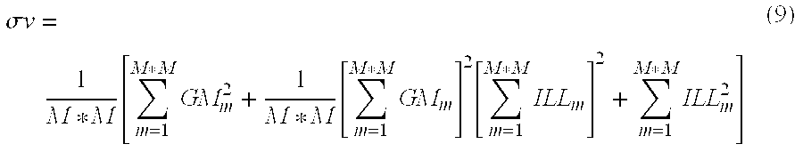
- where:
- GMn represents the m th green-magenta chrominance value of the M×M values within the M×M window.
- ILLn represents the m th illuminant chrominance value of the M×M values within the M×M window.
- Preferably, M=2.
- Finally, the chroma control value is found by passing the chroma edge value through a LUT. This can be illustrated with the following equation:

- where:
- a is an arbitrary constant, preferably 1.5
- b is an arbitrary constant, preferably 175
- d is an arbitrary constant, preferably 150.
- Cv is the chroma control value for a particular M×M window.
- Thus, the chroma control value will be high when the corresponding windows of the chrominance channels contain at least one blue pixel, and the window has a high variance of color. The chroma control value will be zero if the window contains no blue pixels. Additionally, the chroma control value will be zero if the pixels in the window have identical chrominance channel values.
- The
pedestal splitter 120 shown in FIG. 3, is shown in more detail in FIG. 4. The luminancedigital image 107 is input to afrequency splitter 134, along with thespatial filter 116. Alowpass signal 136 is created by convolving the luminancedigital image 107 with thespatial filter 116. Convolution is well known in the art. Ahighpass signal 138 is also produced by the frequency splitter by performing a pixel by pixel difference operation, wherein the lowpass signal is subtracted from the luminancedigital image 107. - h(x,y)=L(x,y)−1(x,y) (11)
- where:
- L(x,y) represents the value of the pixel of the luminance digital image at the (x,y) location.
- l(x,y) represents the value of the lowpass signal at the (x,y) location.
- h(x,y) represents the value of the highpass signal at the (x,y) location.
- Note that the sum of the pedestal and the highpass signals is the luminance digital image.
- The
lowpass signal 136 and thechroma control signal 114 are input to the lumacontrol signal generator 140 for generating theluma control signal 142. Alternatively, the luminance digital image or a spatial filtered version of the luminance digital image or the green channel from the original digital image could be input to the lumacontrol signal generator 140 in place of thelowpass signal 136. The luma control signal 142 controls the effect of the spatial filter on the luminancedigital image 107. - The luma control signal is created as shown in FIG. 5. First, the non-directional gradient G of the
lowpass signal 136 is calculated by thegradient calculator 150 and output as thegradient signal 152. This calculation is performed by first calculating vertical and horizontal gradients with a spatial filter called a gradient filter. - Although a variety of different gradient filters can be used, the preferred embodiment of the present invention uses two one-dimensional Prewitt spatial filters to generate a vertical and a horizontal gradient value for each input pixel value given by equation (12) and (13)

- respectively.
- The
non-directional gradient signal 152 is the square root of the sum of the squares of these two gradients. Thecontrol signal applicator 154 inputs both thegradient signal 152 and thechroma control signal 114 and produces theluma control signal 142. The values of theluma control signal 142 are in the range of 0 to 1, and are found by applying a gradient threshold that is dependent on the value of thechroma control signal 114 to thegradient signal 152. Theluma control signal 142 has a value of 1.0 corresponding to “edge” regions and a value of 0.0 corresponding to “detail” regions in the original digital image and intermediate values for regions that are not easily classified as “edge” or “detail”. Thus, classification of “edge” and “detail” regions in theluma control signal 114 is dependent on the chrominance channels. In the preferred embodiment, a classification of “edge” can be attained more easily (i.e. the gradient signal requirement is lowered) in the luma control signal when the chrominance channels meet certain requirements (e.g. at least one blue pixel and a large variety of colors are represented). The operation of thecontrol signal applicator 154 can be expressed as an equation:
- where:
- Lc(x,y) is the value of the luma control signal 142 at the (x,y) location.
- G(x,y) is the value of the
gradient signal 152 at the (x,y) location. - p is a location-dependent threshold that is dependent on the value of the
chroma control signal 114 and is preferably: - p(x,y)=max(0,f−Cv(x,y)) (15)
- where:
- f is an arbitrary constant, preferably 68.
- Notice that the
chroma control signal 114 is derived from the chrominance channels, and the luma control signal is derived from thechroma control signal 114. Therefore, the luma control signal is derived in part from thechroma control signal 114. The highpass signal and theluma control signal 142 are input to amultiplier 144 for generating a modifiedhighpass signal 146 by performing a pixel-by-pixel multiplication, according to the equation: - hm(x,y)=h(x,y)*1c(x,y) (16)
- where:
- hm(x,y) represents the value of the modified
highpass signal 146 at the (x,y) location. - lc(x,y) represents the value of the luma control signal 142 at the (x,y) location.
- h(x,y) represents the value of the
highpass signal 138 at the (x,y) location. - Note that the sum of the pedestal and the highpass signals is the luminance digital image.
- Finally, the
pedestal signal 122 is produced by anadder 132 that inputs the modifiedhighpass signal 146 and thelowpass signal 136 and adds these input signals according to (x,y) location. - It is instructive to notice that the
chroma control signal 114 of FIG. 2 has a large value for image pixels corresponding to windows containing blue pixels and a high variance of color. In turn, a high chroma control value results in a more inclusive requirement for luminance gradient to have a value of 1 (i.e. be classified as an edge) in the luma control signal 142 of FIG. 4. In that case, the modifiedhighpass signal 146 value is then similar to thehighpass signal 138 value, and thepedestal signal 122 is then similar in value to the luminancedigital image 107, while thetexture signal 130 value is zero. Thepedestal signal 122 of FIG. 3 is then modified by the tonescale function applicator 124 according to thetone scale function 203, compressing the edge. - Stated another way, the chrominance channels of the original digital image are used to locally vary a threshold that is applied to the gradient of the luminance digital image to distinguish “edge” (high gradient) and “detail” (low gradient) regions. The highpass information of the edge regions is affected by the tone scale function, resulting in an image having compressed dynamic range. However, the highpass information of the detail regions is not affected by the tone scale function, so the highpass detail is preserved in these regions. Thus, using the chrominance digital image portion of the original digital image improves the method of application of a tone scale function to a digital image.
- The discussion to this point described the generic method of the present invention. In the discussion to follow, a specific embodiment of the method will be described. The preferred embodiment of the
pedestal splitter 120 is shown in FIG. 6, where a pyramid representation of the image is used so that the producedpedestal signal 122 is a result of removing texture information at many different scales. The luminancedigital image 107 is input to thepyramid constructor 156, which outputs animage pyramid representation 108. Theimage pyramid representation 108 contains all of the information that is contained in the luminancedigital image 107, and theimage pyramid representation 108 can be easily converted back to the luminancedigital image 107. Theimage pyramid representation 108 includes several image signals. Theimage pyramid representation 108 includes the base digital image, which is essentially a smaller (fewer pixels) version of the luminancedigital image 107, and residual images, which contain highpass information from different scales (i.e. the residual images contain bandpass information). Thepyramid representation 108 is input to thepedestal reconstructor 158, which combines the image signals of theimage pyramid representation 108 in such a manner that the texture information is removed, forming thepedestal signal 122. - The
pyramid constructor 156 is illustrated in more detail in FIG. 7. Adigital image channel 164 is input to thepyramid level module 115 1. Thepyramid level module 115 produces a first basedigital image 103 1 and residual digital image 104 1. The residual digital image has the same number of rows and columns of pixels as thedigital image channel 164. The base image channel has 1/Q the number of rows and 1/Q the number of columns of pixels of thedigital image channel 164. Preferably Q=2. Thebase image channel 103 1 produced by the firstpyramid level module 115 1 is input to the secondpyramid level module 115 2, producing a secondbase image channel 103 2 and a second residual image 104 2. The secondbase image channel 103 2 has 1/Q2 the number of rows and 1/Q2 the number of columns of thedigital image channel 164, while the second residual digital image 104 2 has the same number of rows and columns of pixels as the firstbase image channel 103 1. The process iteratively continues N times, when the finalpyramid level module 115 N inputs the N−1th base image channel and produces the Nthbase image channel 103 N and the N residual digital image 104 N. The base image channel is a digital image channel, so the pyramid level module always inputs a digital image channel. The digital image channel input to the first pyramid level module can be considered the 0th base image channel. - FIG. 8 fully illustrates the
pyramid level module 115. The nthbase image channel 103 n is input to ablock averager 170 for producing the n+1thbase image channel 103 n+1. Theblock averager 170 produces a new digital image channel whereby each pixel value of the new digital image channel is formed by determining the mean pixel value of corresponding Q×Q non-overlapping blocks in the nthbase image channel 103 n. This technique for reducing the resolution of an image by an integer factor is well known in the art of image processing, as is applying a lowpass convolution filter followed by a sampling operation. The output of the block averager is the base image channel n+1 103 n+1, which is also an output of thepyramid level module 115. In the process of generating the reduced resolutionbase image channel 103 n+1, highpass information is discarded. The residual signal contains the discarded highpass information such that thebase image channel 103 n+1 and the residual image channel 104 n+1 can be combined to form thebase image channel 103 n. To produce the residual image channel 104 n+1 thebase image channel 103 n+1 output from theblock averager 170 is passed to aninterpolator 172 for interpolation by the factor Q. Preferably, theinterpolator 172 performs a standard bilinear interpolation by a factor of two. The preferred bilinear interpolation is such that the phase of the interpolated image is that same as that of thebase image channel 103 n. Such bilinear interpolation is commonly known and practiced in the art of image processing and will not be further discussed. The output of theinterpolator 172 is the interpolatedbase image channel 174. The interpolatedbase image channel 174 is input to thedifferencer 176. Thedifferencer 176 calculates the residual image channel 104 n+1 by subtracting the interpolatedbase image channel 174 from thebase image channel 103 n, according to the equation: - r(x,y)=b(x,y)−bi(x,y) (17)
- where:
- r(x,y) represents the value of the pixel of the residual image channel 104 n+1 at the (x,y) location.
- b(x,y) represents the value of the nth
base image channel 103 n at the (x,y) location. - bi(x,y) represents the value of the interpolated
base image channel 174 at the (x,y) location. - From the previous equation, it is easy to see that the base
digital image 103 n can be formed from the basedigital image 103 n+1 and the residual digital image 104 n+1 through a reconstruction process. The process includes the steps of interpolating the basedigital image 103 n+1, then adding the residual digital image 104 n+1. By extension, thedigital image channel 164 shown in FIG. 7 can be represented as a collection of residual digital images 104 1-N and one basedigital image 103 N. The perfect reconstruction of thedigital image channel 164 is an iterative process where one base digital image and the corresponding residual image are used to create a higher resolution base digital image, which in turn is used with the next residual digital image to create an even higher resolution base digital image. In the preferred embodiment, N=8 pyramid levels are used in the pyramid representation. Perfect reconstruction of an image pyramid is well known. - One iteration of the
pedestal reconstructor 158 of FIG. 6 is shown in greater detail in FIG. 9. The pedestal reconstructor 158 generates apedestal signal 122 by performing the reconstruction process with the modification that at each pyramid level, image texture is removed, or left out of the reconstruction. The iterative pedestal reconstructor inputs thepedestal signal 122 n, which is the pedestal signal at resolution level n. For resolution level n=N (lowest resolution level represented in the image pyramid representation 108), thepedestal signal N 122 N is set equal to the lowest resolutionbase image channel 103 N. The pedestal reconstruction module inputs thepedestal signal n 122 n and outputs a higherresolution pedestal signal 122 n−1. Thepedestal signal 122 of FIG. 6 is the highest resolution (final)pedestal signal 122 0. - Referring again to FIG. 9, the
pedestal signal n 122 n is input to afrequency splitter 134. Thefrequency splitter 134 applies aspatial filter 116 to the pedestal signal, generating thelowpass signal 136. Thespatial filter 116 is lowpass in nature, attenuating any high frequency content in thepedestal signal 122 n. Thefrequency splitter 134 also outputs ahighpass signal 138 in the manner previously described (similar to Equation 11). Thehighpass signal 138 is calculated as the difference between thepedestal signal n 122 n and thelowpass signal 136. - The
lowpass signal 136 and thechroma control signal 114 are input to the lumacontrol signal generator 180 for generating theluma control signal 182. The operation of the lumacontrol signal generator 180 will be described in more detail hereinbelow. Theluma control signal 182 has a value near 1.0 corresponding to “edge” regions in luminancedigital image 107, and a value near 0 for other regions, with intermediate values. Themultiplier 144 multiplies thehighpass signal 138 and theluma control signal 182, forming the modifiedhighpass signal 146. The modified highpass signal is then added by anadder 132 to thelowpass signal 136, resulting in a signal that has the same pixel values as thepedestal signal 122 n in edge regions and that is smoothed in non-edge regions. The signal output from theadder 132 1 is interpolated by a factor Q by theinterpolator 172 and then added by asecond adder 132 2 to the residual image channel 104 n, resulting in the next higherresolution pedestal signal 122 n−1. - An alternative of one iteration of the
pedestal reconstructor 158 of FIG. 6 is shown in greater detail in FIG. 10. Referring again to FIG. 10, thepedestal signal n 122 n is input to afrequency splitter 134. Thefrequency splitter 134 applies aspatial filter 116 to the pedestal signal, generating thelowpass signal 136. Thespatial filter 116 is lowpass in nature, attenuating any high frequency content in thepedestal signal 122 n. - The
lowpass signal 136 and thechroma control signal 114 are input to the lumacontrol signal generator 180 for generating theluma control signal 182, in identical fashion as in regard to FIG. 9. Again, theluma control signal 182 has a value near 1.0 corresponding to “edge” regions in luminancedigital image 107, and a value near 0 for other regions, with intermediate values. - The
luma control signal 182 is interpolated by a factor Q by aninterpolator 172, and multiplied by the residual image channel 104 n by amultiplier 144, resulting in a signal that is zero in non-edge regions and maintains the values of the residual image channel 104 n in edge regions. The resulting signal is added with anadder 132 to the signal resulting from interpolating with aninterpolator 172 the pedestal signal n, forming thepedestal signal 122 n−1. Thus, thepedestal signal 122 n−1 is simply an interpolated version of the pedestal signal n, with the addition of residual image channel 104 n content in edge regions. - FIGS. 9 and 10 illustrate two different iterative pedestal level reconstructors 158 for creating a higher resolution pedestal signal 122 from a starting pedestal signal. By iterating either of these pedestal level reconstructors, a
pedestal signal 122 can be generated from thepyramid image representation 108 of FIG. 6. In the preferred embodiment, thepyramid image representation 108 has 8 levels. In generating thepedestal signal 122, thereconstructor 158 shown in FIG. 9 is used to generatepedestal signals 122 7 to 122 4, and thereconstructor 158 shown in FIG. 10 is used to generate the remaining pedestal signals, including thefinal pedestal signal 122 output from thepedestal splitter 120 shown in FIG. 3. - FIG. 11 illustrates the luma
control signal generator 180 that is used to create the luma control signal 182 for use in generating the pedestal signal when reconstructing an image pyramid representation, as shown in FIGS. 9 and 10. The lumacontrol signal generator 180 operates at each pyramid level in a very similar fashion to the lumacontrol signal generator 140 that is used to create thepedestal signal 122 already described in regard to FIG. 5. In accordance with FIGS. 9 and 10, aluma control signal 182 n is generated for each of the resolution levels during the pedestal reconstruction. - First, the non-directional gradient G of the
lowpass signal 136 n at resolution level n is calculated by thegradient calculator 150 and output as thegradient signal 152. This calculation has already been described. - The
control signal applicator 154 inputs thegradient signal 152 thechroma control signal 114 n, and optionally the luma control signal 182 n+1 (the luma control signal previously calculated from the previous lower resolution) and produces theluma control signal 182 n. The values of theluma control signal 182 n are in the range of 0 to 1, and are found by applying a gradient threshold that is dependent on both the value of thechroma control signal 114 n and theluma control signal 182 n+1 to thegradient signal 152. Theluma control signal 182 n has a value of 1.0 corresponding to “edge” regions and a value of 0.0 corresponding to “detail” regions in the original digital image and intermediate values for regions that are not easily classified as “edge” or “detail”. In the preferred embodiment, a classification of “edge” can be attained more easily (i.e. the gradient signal requirement is lowered) in the luma control signal when the chrominance channels meet certain requirements (e.g. at least one blue pixel and a large variety of colors are represented.) In addition, the classification of “edge” is more difficult to attain (i.e. the gradient signal requirement is increased) in the luma control signal 182 n where the corresponding location in the previous resolutionluma control signal 182 n+1 was not classified as an “edge” (i.e. the pixel value was not 1.0). The operation of thecontrol signal applicator 154 can be expressed as an equation:
- where
- Lc(x,y) is the value of the luma control signal 182 at the (x,y) location;
- G(x,y) is the value of the
gradient signal 152 at the (x,y) location; - p is a threshold that is dependent on the value of the
chroma control signal 114 and the luma control signal n+1 182 n+1 and is preferably: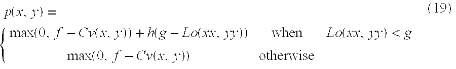
- where:
- f is an arbitrary constant, preferably 68;
- h is an arbitrary constant, preferably 1.4;
- g is an arbitrary constant, preferably 0.4; and
- Lo(xx,yy) is the value of the luma control signal n+1 at the location (xx,yy) that corresponds to the location (x,y) in the current resolution level n.
- When Q=2, the value of xx=(x−1/2)/2 for example. The value of the luma control signal Lo(xx,yy) must be found by interpolation (preferably bilinear interpolation) when either xx or yy is not an integer. All other variables have been previously defined.
- Notice that the
chroma control signal 114 is derived from the chrominance channels using an appropriate value of M (window size) such that the chroma control signal has an appropriate number of pixels. The luma control signal is derived from thechroma control signal 114. Therefore, the luma control signal is derived in part from thechroma control signal 114. In addition, theluma control signal 182 n also has a dependence on a previously calculated low resolution version of theluma control signal 182 n+1. Those skilled in the art will recognize that theluma control signal 182 n could be derived in part from any of the lower resolution versions of the luma control signal. In addition, theluma control signal 182 n could also be derived from a chroma control signal at any level of resolution with appropriate re-sizing. - The present invention can be employed with any number of pyramid levels. Noise in images is generally a function of spatial resolution and is also more objectionable for the higher spatial resolution pyramid levels. The optimal number of pyramid levels depends on the texture removal goals of the digital imaging system designer and on the size of the digital images being processed. The preferred embodiment of the present invention uses 8 pyramid levels for effective texture and noise removal for digital images of size 1024 by 1536 pixels. For processing digital images of greater spatial resolution, such as 2048 by 3072 pixel, 9 pyramid levels are used. For processing digital images of lower spatial resolution, such as 512 by 768 pixels, 7 pyramid levels are used.
- The method of the present invention can be performed in a digital camera or in a digital printer. An operator interface, such as the
display device 50 and theinput control device 60 shown in FIG. 1 can be used by an operator to identify a target color, for example by positioning a cursor on an area of a scene displayed ondisplay device 50. - The invention has been described in detail with particular reference to certain preferred embodiments thereof, but it will be understood that variations and modifications can be effected within the spirit and scope of the invention.
- 10 image capture device
- 20 digital image processor
- 30 image output device
- 40 general control computer
- 50 display device
- 60 input control device
- 70 offline memory device
- 101 original digital image
- 102 enhanced digital image
- 103 1-N base image channel
- 104 1-N residual image channel
- 107 luminance digital image
- 108 image pyramid representation
- 109 chrominance digital image
- 112 chroma control signal generator
- 113 enhanced luminance digital image
- 114 chroma control signal
- 115 1-N pyramid level module
- 116 spatial filter
- 120 pedestal splitter
- 122 0-N pedestal signal
- 124 tone scale function applicator
- 126 modified pedestal signal
- 128 texture generator
- 130 texture signal
- 132 adder
- 134 frequency splitter
- 136 lowpass signal
- 138 highpass signal
- 140 luma control signal generator
- 142 luma control signal
- 144 multiplier
- 146 modified highpass signal
- 150 gradient calculator
- 152 gradient signal
- 154 control signal applicator
- 156 pyramid constructor
- 158 pedestal reconstructor
- 164 digital image channel
- 170 block averager
- 172 interpolator
- 174 interpolated base image channel
- 176 differencer
- 180 luma control signal generator
- 182 luma control signal
- 203 tone scale function
- 210 LCC conversion module
- 220 RGB conversion module
- 230 tone scale function generator
- 240 luminance enhancer
Claims (20)
Priority Applications (1)
| Application Number | Priority Date | Filing Date | Title |
|---|---|---|---|
| US10/294,860 US7280703B2 (en) | 2002-11-14 | 2002-11-14 | Method of spatially filtering a digital image using chrominance information |
Applications Claiming Priority (1)
| Application Number | Priority Date | Filing Date | Title |
|---|---|---|---|
| US10/294,860 US7280703B2 (en) | 2002-11-14 | 2002-11-14 | Method of spatially filtering a digital image using chrominance information |
Publications (2)
| Publication Number | Publication Date |
|---|---|
| US20040096103A1 true US20040096103A1 (en) | 2004-05-20 |
| US7280703B2 US7280703B2 (en) | 2007-10-09 |
Family
ID=32297057
Family Applications (1)
| Application Number | Title | Priority Date | Filing Date |
|---|---|---|---|
| US10/294,860 Active 2025-11-16 US7280703B2 (en) | 2002-11-14 | 2002-11-14 | Method of spatially filtering a digital image using chrominance information |
Country Status (1)
| Country | Link |
|---|---|
| US (1) | US7280703B2 (en) |
Cited By (27)
| Publication number | Priority date | Publication date | Assignee | Title |
|---|---|---|---|---|
| US20030228067A1 (en) * | 2002-06-05 | 2003-12-11 | Canon Kabushiki Kaisha | Image processing apparatus, image processing method, and computer program |
| US20040234151A1 (en) * | 2003-05-22 | 2004-11-25 | Thal German Von | Methods and apparatus for enhanced viewing of aerial refueling operations |
| US20050134734A1 (en) * | 2003-12-17 | 2005-06-23 | Eastman Kodak Company | Noise reduction in color digital images using pyramid decomposition |
| US20060170978A1 (en) * | 2005-01-31 | 2006-08-03 | Qing Gao | Image processing method, image processing apparatus and image processing program |
| US20060222265A1 (en) * | 2005-03-31 | 2006-10-05 | Renato Keshet | Scale-space self-similarity image processing |
| US20060228043A1 (en) * | 2005-03-30 | 2006-10-12 | Pioneer Corporation | Image processing apparatus |
| US20060280363A1 (en) * | 2005-06-14 | 2006-12-14 | Canon Kabushiki Kaisha | Image processing apparatus and method, computer program, and storage medium |
| US20070121094A1 (en) * | 2005-11-30 | 2007-05-31 | Eastman Kodak Company | Detecting objects of interest in digital images |
| US20070126921A1 (en) * | 2005-11-30 | 2007-06-07 | Eastman Kodak Company | Adjusting digital image exposure and tone scale |
| US20070126876A1 (en) * | 2005-11-30 | 2007-06-07 | Eastman Kodak Company | Locating digital image planar surfaces |
| US20080144963A1 (en) * | 2006-12-14 | 2008-06-19 | Shih-Yao Lin | Method and Related Apparatus for Modifying Color Saturation of a Display Device |
| US20090160968A1 (en) * | 2007-12-19 | 2009-06-25 | Prentice Wayne E | Camera using preview image to select exposure |
| US20090310880A1 (en) * | 2008-06-13 | 2009-12-17 | Kazuki Yokoyama | Signal processing apparatus and method, and program |
| US20100014773A1 (en) * | 2006-04-28 | 2010-01-21 | Takeshi Ito | Visual processing apparatus, visual processing method, program, recording medium, display, and integrated circuit |
| US20100283861A1 (en) * | 2009-05-07 | 2010-11-11 | Canon Kabushiki Kaisha | Image processing apparatus and image processing method |
| US7881549B2 (en) | 2005-10-12 | 2011-02-01 | Panasonic Corporaiton | Visual processing device, display device, visual processing method, program, and integrated circuit |
| US7894684B2 (en) * | 2006-04-19 | 2011-02-22 | Panasonic Corporation | Visual processing device, visual processing method, program, display device, and integrated circuit |
| US20110052047A1 (en) * | 2009-09-02 | 2011-03-03 | Tandent Vision Science, Inc. | System and method for generating an intrinsic image using tone mapping and log chromaticity |
| US20110142351A1 (en) * | 2009-12-15 | 2011-06-16 | Ability Enterprise Co., Ltd. | System and method for processing an image edge |
| US20110268368A1 (en) * | 2009-01-28 | 2011-11-03 | Fujitsu Limited | Image processing apparatus and image processing method |
| US20110299772A1 (en) * | 2009-02-13 | 2011-12-08 | Janssen Johannes H M | Image processing system for processing a digital image and image processing method of processing a digital image |
| US20120069226A1 (en) * | 2010-09-21 | 2012-03-22 | Canon Kabushiki Kaisha | Image processing apparatus that corrects for chromatic aberration for taken image, image pickup apparatus, method of correcting for chromatic aberration of magnification therefor, and storage medium |
| US20140320693A1 (en) * | 2006-04-21 | 2014-10-30 | Megachips Corporation | Image processing apparatus having a plurality of image processing blocks that are capable of real-time processing of an image signal |
| US20160104438A1 (en) * | 2014-10-06 | 2016-04-14 | Samsung Electronics Co., Ltd. | Display device and method of controlling the same |
| EP3076364A1 (en) * | 2015-03-30 | 2016-10-05 | Imagination Technologies Limited | Image filtering based on image gradients |
| US20170264790A1 (en) * | 2016-03-10 | 2017-09-14 | Fuji Xerox Co., Ltd. | Image processing device, image processing method, and non-transitory computer readable medium |
| EP2055093B1 (en) * | 2006-08-07 | 2017-11-01 | QUALCOMM Incorporated | Adaptive spatial image filter for filtering image information |
Families Citing this family (13)
| Publication number | Priority date | Publication date | Assignee | Title |
|---|---|---|---|---|
| US20050094003A1 (en) * | 2003-11-05 | 2005-05-05 | Per Thorell | Methods of processing digital image and/or video data including luminance filtering based on chrominance data and related systems and computer program products |
| US8203617B2 (en) * | 2003-11-05 | 2012-06-19 | Telefonaktiebolaget Lm Ericsson (Publ) | Apparatus and method for increasing coding efficiency with an adaptive pre-filter |
| US20060104537A1 (en) * | 2004-11-12 | 2006-05-18 | Sozotek, Inc. | System and method for image enhancement |
| JP4890974B2 (en) * | 2006-06-29 | 2012-03-07 | キヤノン株式会社 | Image processing apparatus and image processing method |
| JP4890973B2 (en) | 2006-06-29 | 2012-03-07 | キヤノン株式会社 | Image processing apparatus, image processing method, image processing program, and storage medium |
| JP4926568B2 (en) * | 2006-06-29 | 2012-05-09 | キヤノン株式会社 | Image processing apparatus, image processing method, and image processing program |
| US8433155B2 (en) * | 2006-12-28 | 2013-04-30 | Texas Instruments Incorporated | Gaussian noise rejection with directional variance capabilities for use in image processing |
| US20080159649A1 (en) * | 2006-12-29 | 2008-07-03 | Texas Instruments Incorporated | Directional fir filtering for image artifacts reduction |
| TW201001334A (en) * | 2008-06-20 | 2010-01-01 | Altek Corp | Adjustment method of color tone for digital image and electronic apparatus thereof |
| CN101621608B (en) * | 2008-07-04 | 2012-09-19 | 华晶科技股份有限公司 | Hue adjusting method of digital image and electronic device thereof |
| JP5256001B2 (en) * | 2008-11-20 | 2013-08-07 | 京セラドキュメントソリューションズ株式会社 | Color adjustment apparatus, method and program |
| US8594446B2 (en) * | 2012-01-12 | 2013-11-26 | Eastman Kodak Company | Method for enhancing a digitized document |
| SE536510C2 (en) * | 2012-02-21 | 2014-01-14 | Flir Systems Ab | Imaging method for detail enhancement and noise reduction |
Citations (15)
| Publication number | Priority date | Publication date | Assignee | Title |
|---|---|---|---|---|
| US5012333A (en) * | 1989-01-05 | 1991-04-30 | Eastman Kodak Company | Interactive dynamic range adjustment system for printing digital images |
| US5227863A (en) * | 1989-11-14 | 1993-07-13 | Intelligent Resources Integrated Systems, Inc. | Programmable digital video processing system |
| US5454044A (en) * | 1990-01-29 | 1995-09-26 | Fuji Photo Film Co., Ltd. | Apparatus for enhancing image data using a monotonously decreasing function |
| US5467404A (en) * | 1991-08-14 | 1995-11-14 | Agfa-Gevaert | Method and apparatus for contrast enhancement |
| US5471987A (en) * | 1993-03-30 | 1995-12-05 | Konica Corporation | Method of compressing a dynamic range for a radiation image |
| US5682443A (en) * | 1993-03-24 | 1997-10-28 | Crosfield Electronics Limited | Image color modification method and apparatus employing unsharp masking |
| US5717791A (en) * | 1994-11-10 | 1998-02-10 | Agfa-Gevaert | Image contrast enhancing method |
| US5796870A (en) * | 1995-04-20 | 1998-08-18 | Fuji Photo Film Co., Ltd. | Method and apparatus for compressing dynamic ranges of images |
| US5905817A (en) * | 1995-12-25 | 1999-05-18 | Fuji Photo Film Co., Ltd. | Image reproducing method and apparatus using dynamic range compression based on an unsharp signal generated by IIR filter |
| US5907642A (en) * | 1995-07-27 | 1999-05-25 | Fuji Photo Film Co., Ltd. | Method and apparatus for enhancing images by emphasis processing of a multiresolution frequency band |
| US5991457A (en) * | 1995-09-29 | 1999-11-23 | Fuji Photo Film Co., Ltd. | Multi-resolution transforming, image processing and dynamic range compressing method and apparatus |
| US6167165A (en) * | 1998-11-25 | 2000-12-26 | Eastman Kodak Company | Method for adjusting image detail to compensate for an applied tone scale |
| US6285798B1 (en) * | 1998-07-06 | 2001-09-04 | Eastman Kodak Company | Automatic tone adjustment by contrast gain-control on edges |
| US6317521B1 (en) * | 1998-07-06 | 2001-11-13 | Eastman Kodak Company | Method for preserving image detail when adjusting the contrast of a digital image |
| US6438264B1 (en) * | 1998-12-31 | 2002-08-20 | Eastman Kodak Company | Method for compensating image color when adjusting the contrast of a digital color image |
-
2002
- 2002-11-14 US US10/294,860 patent/US7280703B2/en active Active
Patent Citations (16)
| Publication number | Priority date | Publication date | Assignee | Title |
|---|---|---|---|---|
| US5012333A (en) * | 1989-01-05 | 1991-04-30 | Eastman Kodak Company | Interactive dynamic range adjustment system for printing digital images |
| US5227863A (en) * | 1989-11-14 | 1993-07-13 | Intelligent Resources Integrated Systems, Inc. | Programmable digital video processing system |
| US5454044A (en) * | 1990-01-29 | 1995-09-26 | Fuji Photo Film Co., Ltd. | Apparatus for enhancing image data using a monotonously decreasing function |
| US5805721A (en) * | 1991-08-14 | 1998-09-08 | Agfa-Gevaert | Method and apparatus for contrast enhancement |
| US5467404A (en) * | 1991-08-14 | 1995-11-14 | Agfa-Gevaert | Method and apparatus for contrast enhancement |
| US5682443A (en) * | 1993-03-24 | 1997-10-28 | Crosfield Electronics Limited | Image color modification method and apparatus employing unsharp masking |
| US5471987A (en) * | 1993-03-30 | 1995-12-05 | Konica Corporation | Method of compressing a dynamic range for a radiation image |
| US5717791A (en) * | 1994-11-10 | 1998-02-10 | Agfa-Gevaert | Image contrast enhancing method |
| US5796870A (en) * | 1995-04-20 | 1998-08-18 | Fuji Photo Film Co., Ltd. | Method and apparatus for compressing dynamic ranges of images |
| US5907642A (en) * | 1995-07-27 | 1999-05-25 | Fuji Photo Film Co., Ltd. | Method and apparatus for enhancing images by emphasis processing of a multiresolution frequency band |
| US5991457A (en) * | 1995-09-29 | 1999-11-23 | Fuji Photo Film Co., Ltd. | Multi-resolution transforming, image processing and dynamic range compressing method and apparatus |
| US5905817A (en) * | 1995-12-25 | 1999-05-18 | Fuji Photo Film Co., Ltd. | Image reproducing method and apparatus using dynamic range compression based on an unsharp signal generated by IIR filter |
| US6285798B1 (en) * | 1998-07-06 | 2001-09-04 | Eastman Kodak Company | Automatic tone adjustment by contrast gain-control on edges |
| US6317521B1 (en) * | 1998-07-06 | 2001-11-13 | Eastman Kodak Company | Method for preserving image detail when adjusting the contrast of a digital image |
| US6167165A (en) * | 1998-11-25 | 2000-12-26 | Eastman Kodak Company | Method for adjusting image detail to compensate for an applied tone scale |
| US6438264B1 (en) * | 1998-12-31 | 2002-08-20 | Eastman Kodak Company | Method for compensating image color when adjusting the contrast of a digital color image |
Cited By (75)
| Publication number | Priority date | Publication date | Assignee | Title |
|---|---|---|---|---|
| US8023764B2 (en) * | 2002-06-05 | 2011-09-20 | Canon Kabushiki Kaisha | Image processing apparatus, image processing method, and a program, for removing low-frequency noise from image data |
| US8744209B2 (en) | 2002-06-05 | 2014-06-03 | Canon Kabushiki Kaisha | Image processing apparatus and image processing method for visually reducing noise components contained in a low frequency range of image data |
| US8306357B2 (en) | 2002-06-05 | 2012-11-06 | Canon Kabushiki Kaisha | Image processing apparatus, image processing method, and computer program |
| US20030228067A1 (en) * | 2002-06-05 | 2003-12-11 | Canon Kabushiki Kaisha | Image processing apparatus, image processing method, and computer program |
| US7315656B2 (en) * | 2003-05-22 | 2008-01-01 | The Boeing Company | Methods and apparatus for enhanced viewing of aerial refueling operations |
| US20080063296A1 (en) * | 2003-05-22 | 2008-03-13 | The Boeing Company | Image enhancement for aerial refueling operations |
| US20040234151A1 (en) * | 2003-05-22 | 2004-11-25 | Thal German Von | Methods and apparatus for enhanced viewing of aerial refueling operations |
| US7409101B2 (en) | 2003-05-22 | 2008-08-05 | The Boeing Company | Image enhancement for aerial refueling operations |
| US20050134734A1 (en) * | 2003-12-17 | 2005-06-23 | Eastman Kodak Company | Noise reduction in color digital images using pyramid decomposition |
| US7257271B2 (en) * | 2003-12-17 | 2007-08-14 | Eastman Kodak Company | Noise reduction in color digital images using pyramid decomposition |
| US7702173B2 (en) * | 2005-01-31 | 2010-04-20 | Konica Minolta Holdings, Inc. | Image processing method, image processing apparatus and image processing program |
| US20060170978A1 (en) * | 2005-01-31 | 2006-08-03 | Qing Gao | Image processing method, image processing apparatus and image processing program |
| US20060228043A1 (en) * | 2005-03-30 | 2006-10-12 | Pioneer Corporation | Image processing apparatus |
| US7702175B2 (en) * | 2005-03-30 | 2010-04-20 | Pioneer Corporation | Image processing apparatus for enhancing high frequency components |
| US20060222265A1 (en) * | 2005-03-31 | 2006-10-05 | Renato Keshet | Scale-space self-similarity image processing |
| US7742660B2 (en) * | 2005-03-31 | 2010-06-22 | Hewlett-Packard Development Company, L.P. | Scale-space self-similarity image processing |
| US7826659B2 (en) * | 2005-06-14 | 2010-11-02 | Canon Kabushiki Kaisha | Image processing apparatus and method, computer program, and storage medium dividing an input image into band images |
| US20060280363A1 (en) * | 2005-06-14 | 2006-12-14 | Canon Kabushiki Kaisha | Image processing apparatus and method, computer program, and storage medium |
| US7881549B2 (en) | 2005-10-12 | 2011-02-01 | Panasonic Corporaiton | Visual processing device, display device, visual processing method, program, and integrated circuit |
| US8311357B2 (en) | 2005-10-12 | 2012-11-13 | Panasonic Corporation | Visual processing device, display device, visual processing method, program, and integrated circuit |
| US20110085085A1 (en) * | 2005-10-12 | 2011-04-14 | Haruo Yamashita | Visual processing device, display device, visual processing method, program, and integrated circuit |
| US20070126921A1 (en) * | 2005-11-30 | 2007-06-07 | Eastman Kodak Company | Adjusting digital image exposure and tone scale |
| US7821570B2 (en) | 2005-11-30 | 2010-10-26 | Eastman Kodak Company | Adjusting digital image exposure and tone scale |
| US20070121094A1 (en) * | 2005-11-30 | 2007-05-31 | Eastman Kodak Company | Detecting objects of interest in digital images |
| US20070126876A1 (en) * | 2005-11-30 | 2007-06-07 | Eastman Kodak Company | Locating digital image planar surfaces |
| US7894684B2 (en) * | 2006-04-19 | 2011-02-22 | Panasonic Corporation | Visual processing device, visual processing method, program, display device, and integrated circuit |
| US8406547B2 (en) | 2006-04-19 | 2013-03-26 | Panasonic Corporation | Visual processing device, visual processing method, program, display device, and integrated circuit |
| US20140320693A1 (en) * | 2006-04-21 | 2014-10-30 | Megachips Corporation | Image processing apparatus having a plurality of image processing blocks that are capable of real-time processing of an image signal |
| US9202292B2 (en) * | 2006-04-21 | 2015-12-01 | Megachips Corporation | Image processing apparatus having a plurality of image processing blocks that are capable of real-time processing of an image signal |
| US7903898B2 (en) * | 2006-04-28 | 2011-03-08 | Panasonic Corporation | Visual processing apparatus, visual processing method, program, recording medium, display device, and integrated circuit |
| US8401324B2 (en) | 2006-04-28 | 2013-03-19 | Panasonic Corporation | Visual processing apparatus, visual processing method, program, recording medium, display device, and integrated circuit |
| US20110122148A1 (en) * | 2006-04-28 | 2011-05-26 | Takeshi Ito | Visual processing apparatus, visual processing method, program, recording medium, display device, and integrated circuit |
| US20100014773A1 (en) * | 2006-04-28 | 2010-01-21 | Takeshi Ito | Visual processing apparatus, visual processing method, program, recording medium, display, and integrated circuit |
| US7881550B2 (en) * | 2006-04-28 | 2011-02-01 | Panasonic Corporation | Visual processing apparatus, visual processing method, program, recording medium, display device, and integrated circuit |
| EP2055093B1 (en) * | 2006-08-07 | 2017-11-01 | QUALCOMM Incorporated | Adaptive spatial image filter for filtering image information |
| US8406555B2 (en) * | 2006-12-14 | 2013-03-26 | Au Optronics Corporation | Method and related apparatus for modifying color saturation of a display device |
| US20080144963A1 (en) * | 2006-12-14 | 2008-06-19 | Shih-Yao Lin | Method and Related Apparatus for Modifying Color Saturation of a Display Device |
| US20090160968A1 (en) * | 2007-12-19 | 2009-06-25 | Prentice Wayne E | Camera using preview image to select exposure |
| US9819852B2 (en) | 2007-12-19 | 2017-11-14 | Monument Peak Ventures, Llc | Camera using preview image to select exposure |
| US10142536B2 (en) | 2007-12-19 | 2018-11-27 | Monument Peak Ventures, Llc | Camera using preview image to select exposure |
| US10412296B2 (en) | 2007-12-19 | 2019-09-10 | Monument Peak Ventures, Llc | Camera using preview image to select exposure |
| US8488015B2 (en) | 2007-12-19 | 2013-07-16 | Intellectual Ventures Fund 83 Llc | Camera using preview image to select exposure |
| US20090310880A1 (en) * | 2008-06-13 | 2009-12-17 | Kazuki Yokoyama | Signal processing apparatus and method, and program |
| US20110268368A1 (en) * | 2009-01-28 | 2011-11-03 | Fujitsu Limited | Image processing apparatus and image processing method |
| US8687907B2 (en) * | 2009-01-28 | 2014-04-01 | Fujitsu Limited | Image processing apparatus and image processing method |
| US20110299772A1 (en) * | 2009-02-13 | 2011-12-08 | Janssen Johannes H M | Image processing system for processing a digital image and image processing method of processing a digital image |
| US8559752B2 (en) * | 2009-02-13 | 2013-10-15 | Oce Technologies B.V. | Image processing system for processing a digital image and image processing method of processing a digital image |
| US20100283861A1 (en) * | 2009-05-07 | 2010-11-11 | Canon Kabushiki Kaisha | Image processing apparatus and image processing method |
| US8451340B2 (en) * | 2009-05-07 | 2013-05-28 | Canon Kabushiki Kaisha | Image processing apparatus and image processing method for faithful reconstruction from a tone-converted image |
| WO2011028240A1 (en) * | 2009-09-02 | 2011-03-10 | Tandent Vision Science, Inc. | System and method for generating an intrinsic image using tone mapping and log chromaticity |
| US8346022B2 (en) | 2009-09-02 | 2013-01-01 | Tandent Vision Science, Inc. | System and method for generating an intrinsic image using tone mapping and log chromaticity |
| US20110052047A1 (en) * | 2009-09-02 | 2011-03-03 | Tandent Vision Science, Inc. | System and method for generating an intrinsic image using tone mapping and log chromaticity |
| US20110142351A1 (en) * | 2009-12-15 | 2011-06-16 | Ability Enterprise Co., Ltd. | System and method for processing an image edge |
| US8594452B2 (en) * | 2009-12-15 | 2013-11-26 | Ability Enterprise Co., Ltd. | System and method for processing an image edge |
| US20120069226A1 (en) * | 2010-09-21 | 2012-03-22 | Canon Kabushiki Kaisha | Image processing apparatus that corrects for chromatic aberration for taken image, image pickup apparatus, method of correcting for chromatic aberration of magnification therefor, and storage medium |
| US9118878B2 (en) | 2010-09-21 | 2015-08-25 | Canon Kabushiki Kaisha | Image processing apparatus that corrects for chromatic aberration for taken image, image pickup apparatus, method of correcting for chromatic aberration of magnification therefor, and storage medium |
| US8531579B2 (en) * | 2010-09-21 | 2013-09-10 | Canon Kabushiki Kaisha | Image processing apparatus that corrects for chromatic aberration for taken image, image pickup apparatus, method of correcting for chromatic aberration of magnification therefor, and storage medium |
| US20160104438A1 (en) * | 2014-10-06 | 2016-04-14 | Samsung Electronics Co., Ltd. | Display device and method of controlling the same |
| US11721294B2 (en) * | 2014-10-06 | 2023-08-08 | Samsung Electronics Co., Ltd. | Display device and method of controlling the same |
| US20200258456A1 (en) * | 2014-10-06 | 2020-08-13 | Samsung Electronics Co., Ltd. | Display device and method of controlling the same |
| US10679569B2 (en) * | 2014-10-06 | 2020-06-09 | Samsung Electronics Co., Ltd. | Display device and method of controlling the same |
| US20190027100A1 (en) * | 2014-10-06 | 2019-01-24 | Samsung Electronics Co., Ltd. | Display device and method of controlling the same |
| US10089936B2 (en) * | 2014-10-06 | 2018-10-02 | Samsung Electronics Co., Ltd. | Display device and method of controlling the same |
| US9842386B2 (en) | 2015-03-30 | 2017-12-12 | Imagination Technologies Limited | Image filtering based on image gradients |
| GB2536904B (en) * | 2015-03-30 | 2017-12-27 | Imagination Tech Ltd | Image filtering based on image gradients |
| EP3509034A1 (en) * | 2015-03-30 | 2019-07-10 | Imagination Technologies Limited | Image filtering based on image gradients |
| US10580120B2 (en) | 2015-03-30 | 2020-03-03 | Imagination Technologies Limited | Image filtering based on image gradients |
| CN106027851A (en) * | 2015-03-30 | 2016-10-12 | 想象技术有限公司 | Image filtering based on image gradients |
| GB2536904A (en) * | 2015-03-30 | 2016-10-05 | Imagination Tech Ltd | Image filtering based on image gradients |
| EP3696769A1 (en) * | 2015-03-30 | 2020-08-19 | Imagination Technologies Limited | Image filtering based on image gradients |
| CN112969005A (en) * | 2015-03-30 | 2021-06-15 | 想象技术有限公司 | Method and system for processing images |
| US11244432B2 (en) | 2015-03-30 | 2022-02-08 | Imagination Technologies Limited | Image filtering based on image gradients |
| EP3076364A1 (en) * | 2015-03-30 | 2016-10-05 | Imagination Technologies Limited | Image filtering based on image gradients |
| US20170264790A1 (en) * | 2016-03-10 | 2017-09-14 | Fuji Xerox Co., Ltd. | Image processing device, image processing method, and non-transitory computer readable medium |
| US10560606B2 (en) * | 2016-03-10 | 2020-02-11 | Fuji Xerox Co., Ltd. | Image processing device, image processing method, and non-transitory computer readable medium |
Also Published As
| Publication number | Publication date |
|---|---|
| US7280703B2 (en) | 2007-10-09 |
Similar Documents
| Publication | Publication Date | Title |
|---|---|---|
| US7280703B2 (en) | Method of spatially filtering a digital image using chrominance information | |
| US7181086B2 (en) | Multiresolution method of spatially filtering a digital image | |
| US7672528B2 (en) | Method of processing an image to form an image pyramid | |
| US7020332B2 (en) | Method and apparatus for enhancing a digital image by applying an inverse histogram-based pixel mapping function to pixels of the digital image | |
| US6937775B2 (en) | Method of enhancing the tone scale of a digital image to extend the linear response range without amplifying noise | |
| US6285798B1 (en) | Automatic tone adjustment by contrast gain-control on edges | |
| US6728416B1 (en) | Adjusting the contrast of a digital image with an adaptive recursive filter | |
| US7529425B2 (en) | Denoising method, apparatus, and program | |
| US7876974B2 (en) | Method for improving digital images and an image sensor for sensing the same | |
| JP4210577B2 (en) | Method for enhancing gradation and spatial characteristics of digital images using selective spatial filters | |
| US8068163B2 (en) | Optical imaging systems and methods utilizing nonlinear and/or spatially varying image processing | |
| US6611627B1 (en) | Digital image processing method for edge shaping | |
| US7916940B2 (en) | Processing of mosaic digital images | |
| US7302110B2 (en) | Image enhancement methods and apparatus therefor | |
| US6317521B1 (en) | Method for preserving image detail when adjusting the contrast of a digital image | |
| US6792160B2 (en) | General purpose image enhancement algorithm which augments the visual perception of detail in digital images | |
| US7103228B2 (en) | Local change of an image sharpness of photographic images with masks | |
| JP3465226B2 (en) | Image density conversion processing method | |
| US8514303B2 (en) | Advanced imaging systems and methods utilizing nonlinear and/or spatially varying image processing | |
| US8717456B2 (en) | Optical imaging systems and methods utilizing nonlinear and/or spatially varying image processing | |
| EP1111906A2 (en) | A method for enhancing the edge contrast of a digital image independently from the texture | |
| US7269300B2 (en) | Sharpening a digital image in accordance with magnification values | |
| US7430334B2 (en) | Digital imaging systems, articles of manufacture, and digital image processing methods | |
| Lim et al. | Denoising scheme for realistic digital photos from unknown sources | |
| Sekar et al. | Image enhancement in cell phone cameras using wavelet transform |
Legal Events
| Date | Code | Title | Description |
|---|---|---|---|
| AS | Assignment |
Owner name: EASTMAN KODAK COMPANY, NEW YORK Free format text: ASSIGNMENT OF ASSIGNORS INTEREST;ASSIGNORS:GALLAGHER, ANDREW C.;GINDELE, EDWARD B.;REEL/FRAME:013499/0219 Effective date: 20021113 |
|
| FEPP | Fee payment procedure |
Free format text: PAYOR NUMBER ASSIGNED (ORIGINAL EVENT CODE: ASPN); ENTITY STATUS OF PATENT OWNER: LARGE ENTITY |
|
| STCF | Information on status: patent grant |
Free format text: PATENTED CASE |
|
| FPAY | Fee payment |
Year of fee payment: 4 |
|
| AS | Assignment |
Owner name: CITICORP NORTH AMERICA, INC., AS AGENT, NEW YORK Free format text: SECURITY INTEREST;ASSIGNORS:EASTMAN KODAK COMPANY;PAKON, INC.;REEL/FRAME:028201/0420 Effective date: 20120215 |
|
| AS | Assignment |
Owner name: KODAK IMAGING NETWORK, INC., CALIFORNIA Free format text: PATENT RELEASE;ASSIGNORS:CITICORP NORTH AMERICA, INC.;WILMINGTON TRUST, NATIONAL ASSOCIATION;REEL/FRAME:029913/0001 Effective date: 20130201 Owner name: NPEC INC., NEW YORK Free format text: PATENT RELEASE;ASSIGNORS:CITICORP NORTH AMERICA, INC.;WILMINGTON TRUST, NATIONAL ASSOCIATION;REEL/FRAME:029913/0001 Effective date: 20130201 Owner name: KODAK PORTUGUESA LIMITED, NEW YORK Free format text: PATENT RELEASE;ASSIGNORS:CITICORP NORTH AMERICA, INC.;WILMINGTON TRUST, NATIONAL ASSOCIATION;REEL/FRAME:029913/0001 Effective date: 20130201 Owner name: CREO MANUFACTURING AMERICA LLC, WYOMING Free format text: PATENT RELEASE;ASSIGNORS:CITICORP NORTH AMERICA, INC.;WILMINGTON TRUST, NATIONAL ASSOCIATION;REEL/FRAME:029913/0001 Effective date: 20130201 Owner name: LASER-PACIFIC MEDIA CORPORATION, NEW YORK Free format text: PATENT RELEASE;ASSIGNORS:CITICORP NORTH AMERICA, INC.;WILMINGTON TRUST, NATIONAL ASSOCIATION;REEL/FRAME:029913/0001 Effective date: 20130201 Owner name: KODAK AVIATION LEASING LLC, NEW YORK Free format text: PATENT RELEASE;ASSIGNORS:CITICORP NORTH AMERICA, INC.;WILMINGTON TRUST, NATIONAL ASSOCIATION;REEL/FRAME:029913/0001 Effective date: 20130201 Owner name: EASTMAN KODAK INTERNATIONAL CAPITAL COMPANY, INC., Free format text: PATENT RELEASE;ASSIGNORS:CITICORP NORTH AMERICA, INC.;WILMINGTON TRUST, NATIONAL ASSOCIATION;REEL/FRAME:029913/0001 Effective date: 20130201 Owner name: KODAK REALTY, INC., NEW YORK Free format text: PATENT RELEASE;ASSIGNORS:CITICORP NORTH AMERICA, INC.;WILMINGTON TRUST, NATIONAL ASSOCIATION;REEL/FRAME:029913/0001 Effective date: 20130201 Owner name: FPC INC., CALIFORNIA Free format text: PATENT RELEASE;ASSIGNORS:CITICORP NORTH AMERICA, INC.;WILMINGTON TRUST, NATIONAL ASSOCIATION;REEL/FRAME:029913/0001 Effective date: 20130201 Owner name: PAKON, INC., INDIANA Free format text: PATENT RELEASE;ASSIGNORS:CITICORP NORTH AMERICA, INC.;WILMINGTON TRUST, NATIONAL ASSOCIATION;REEL/FRAME:029913/0001 Effective date: 20130201 Owner name: EASTMAN KODAK COMPANY, NEW YORK Free format text: PATENT RELEASE;ASSIGNORS:CITICORP NORTH AMERICA, INC.;WILMINGTON TRUST, NATIONAL ASSOCIATION;REEL/FRAME:029913/0001 Effective date: 20130201 Owner name: FAR EAST DEVELOPMENT LTD., NEW YORK Free format text: PATENT RELEASE;ASSIGNORS:CITICORP NORTH AMERICA, INC.;WILMINGTON TRUST, NATIONAL ASSOCIATION;REEL/FRAME:029913/0001 Effective date: 20130201 Owner name: KODAK PHILIPPINES, LTD., NEW YORK Free format text: PATENT RELEASE;ASSIGNORS:CITICORP NORTH AMERICA, INC.;WILMINGTON TRUST, NATIONAL ASSOCIATION;REEL/FRAME:029913/0001 Effective date: 20130201 Owner name: QUALEX INC., NORTH CAROLINA Free format text: PATENT RELEASE;ASSIGNORS:CITICORP NORTH AMERICA, INC.;WILMINGTON TRUST, NATIONAL ASSOCIATION;REEL/FRAME:029913/0001 Effective date: 20130201 Owner name: KODAK (NEAR EAST), INC., NEW YORK Free format text: PATENT RELEASE;ASSIGNORS:CITICORP NORTH AMERICA, INC.;WILMINGTON TRUST, NATIONAL ASSOCIATION;REEL/FRAME:029913/0001 Effective date: 20130201 Owner name: KODAK AMERICAS, LTD., NEW YORK Free format text: PATENT RELEASE;ASSIGNORS:CITICORP NORTH AMERICA, INC.;WILMINGTON TRUST, NATIONAL ASSOCIATION;REEL/FRAME:029913/0001 Effective date: 20130201 |
|
| AS | Assignment |
Owner name: INTELLECTUAL VENTURES FUND 83 LLC, NEVADA Free format text: ASSIGNMENT OF ASSIGNORS INTEREST;ASSIGNOR:EASTMAN KODAK COMPANY;REEL/FRAME:030271/0517 Effective date: 20130201 |
|
| FPAY | Fee payment |
Year of fee payment: 8 |
|
| AS | Assignment |
Owner name: MONUMENT PEAK VENTURES, LLC, TEXAS Free format text: ASSIGNMENT OF ASSIGNORS INTEREST;ASSIGNOR:INTELLECTUAL VENTURES FUND 83 LLC;REEL/FRAME:041941/0079 Effective date: 20170215 |
|
| MAFP | Maintenance fee payment |
Free format text: PAYMENT OF MAINTENANCE FEE, 12TH YEAR, LARGE ENTITY (ORIGINAL EVENT CODE: M1553); ENTITY STATUS OF PATENT OWNER: LARGE ENTITY Year of fee payment: 12 |
|
| AS | Assignment |
Owner name: MONUMENT PEAK VENTURES, LLC, TEXAS Free format text: RELEASE BY SECURED PARTY;ASSIGNOR:INTELLECTUAL VENTURES FUND 83 LLC;REEL/FRAME:064599/0304 Effective date: 20230728 |