US20040042685A1 - Image warping correction in forming 360 degree panoramic images - Google Patents
Image warping correction in forming 360 degree panoramic images Download PDFInfo
- Publication number
- US20040042685A1 US20040042685A1 US10/230,786 US23078602A US2004042685A1 US 20040042685 A1 US20040042685 A1 US 20040042685A1 US 23078602 A US23078602 A US 23078602A US 2004042685 A1 US2004042685 A1 US 2004042685A1
- Authority
- US
- United States
- Prior art keywords
- pixel
- cos
- image
- determining
- images
- Prior art date
- Legal status (The legal status is an assumption and is not a legal conclusion. Google has not performed a legal analysis and makes no representation as to the accuracy of the status listed.)
- Granted
Links
- 239000011159 matrix material Substances 0.000 claims abstract description 35
- 238000000034 method Methods 0.000 claims abstract description 15
- 230000003287 optical effect Effects 0.000 claims abstract description 13
- 238000010422 painting Methods 0.000 claims abstract description 4
- 101150092200 alx-1 gene Proteins 0.000 description 12
- 230000006978 adaptation Effects 0.000 description 1
- 238000006243 chemical reaction Methods 0.000 description 1
- 238000010586 diagram Methods 0.000 description 1
- 239000003973 paint Substances 0.000 description 1
- 238000009877 rendering Methods 0.000 description 1
- 239000011800 void material Substances 0.000 description 1
Images


Classifications
-
- G—PHYSICS
- G06—COMPUTING; CALCULATING OR COUNTING
- G06T—IMAGE DATA PROCESSING OR GENERATION, IN GENERAL
- G06T3/00—Geometric image transformations in the plane of the image
- G06T3/40—Scaling of whole images or parts thereof, e.g. expanding or contracting
- G06T3/4038—Image mosaicing, e.g. composing plane images from plane sub-images
-
- G—PHYSICS
- G06—COMPUTING; CALCULATING OR COUNTING
- G06V—IMAGE OR VIDEO RECOGNITION OR UNDERSTANDING
- G06V10/00—Arrangements for image or video recognition or understanding
- G06V10/10—Image acquisition
- G06V10/12—Details of acquisition arrangements; Constructional details thereof
- G06V10/14—Optical characteristics of the device performing the acquisition or on the illumination arrangements
- G06V10/147—Details of sensors, e.g. sensor lenses
-
- G—PHYSICS
- G06—COMPUTING; CALCULATING OR COUNTING
- G06V—IMAGE OR VIDEO RECOGNITION OR UNDERSTANDING
- G06V10/00—Arrangements for image or video recognition or understanding
- G06V10/10—Image acquisition
- G06V10/16—Image acquisition using multiple overlapping images; Image stitching
Definitions
- This invention relates to digital image stitching and in particular to an image stitching method for generating a 360 degree panoramic image from a sequence of images.
- Digital photography is becoming more popular today as digital cameras and scanners are becoming widely available. Digital images can be created either by capturing a scene using a digital camera or digitizing a traditional film-based photograph using a scanner.
- One particular advantage of digital photography over traditional film-based photography is that digital images can be easily manipulated or edited for better presentation. Digital photography can also be readily distributed over the Internet.
- the desired field of view may be larger than the normal field of view of the camera.
- Digital photography allows a panoramic image to be produced without the need of purchasing special equipment such as a panoramic camera or fisheye lenses.
- a photographer with a digital camera may capture a series of digital pictures of a scene by rotating the camera and taking pictures in a sequence of different directions. The captured images may then be stitched together to produce a panoramic picture of the scene.
- film-based photographs can be digitized, and the panoramic picture can be composed by stitching together the digitized images.
- digital image programs are available for stitching multiple digital images together to form a panoramic picture. Exemplary programs include Ulead Cool 360TM, Live Picture PhotoVistaTM, and MGI PhotoSuite IIITM.
- a conventional image program stitches images by matching corresponding features on two source images and rotating one source image so the corresponding features overlap.
- a 360 degree panoramic image is constructed from a sequence of many images where the last image is stitched to the first image to complete the 360 degree view.
- errors e.g., matching and motion estimation errors
- the last image and the first image that must be compensated so they can be stitched together. Therefore, there is a need for a method to compensate these errors in a reasonable way so the last image can be stitched to the first image.
- a method for creating a 360 degree panoramic image from multiple images includes (1) computing a gross rotation error ⁇ R between a first image and a calculated first image rotated to be stitched to a last image, and (2) spreading the gross rotation error ⁇ R to each pixel of the panoramic image.
- spreading the gross rotation error ⁇ R further includes (4) tracing a pixel in a column on the panoramic image to a camera optical center of the images to form a first ray, (5) determining a second ray originating from the camera optical center that would be rotated by the compensation matrix R c to coincide with the first ray, (6) tracing the second ray to a second pixel on one of the images, and (7) painting the first pixel with color values of the second pixel.
- FIG. 1 illustrates a diagram of a sequence of stitched images to be projected on a cylindrical surface to generate a 360 degree panoramic image in one embodiment of the invention.
- FIG. 2 illustrates a flowchart of a method to generate a 360 degree panoramic image in one embodiment of the invention.
- FIG. 3A illustrates the relative rotation between two adjacent images where the rotation is represented by a rotational axis and a rotational angle in one embodiment.
- FIG. 3B illustrates the relative rotation between two an original first image and a rotated first image that can be stitched to the last image where the rotation is represented by a rotational axis and a rotational angle in one embodiment.
- FIG. 4 illustrates an angle of a column on the cylindrical surface used to calculate a compensation rotation matrix R c in one embodiment.
- FIG. 5 illustrates the compensation of a pixel on the cylindrical surface using the compensation rotation matrix R c in one embodiment.
- a computer generates a 360 degree panoramic image by determining the focal length of the camera, matching feature points between adjacent images, and using the focal length and the feature points to determine the positions of the adjacent images around a fixed camera optical center.
- the computer assumes that the adjacent images are taken by a camera rotated from the fixed camera optical center. After the images are arranged about the camera optical center, their pixels can be projected onto a cylindrical surface (or vice versa) to generate the 360 degree panoramic image.
- determining the focal length, matching feature points, and determining the position of adjacent images please see U.S. patent application Ser. No. 09/665,917, filed Sep. 20, 2001, which is incorporated by reference in its entirety.
- FIG. 1 illustrates an exemplary sequence of images P[0], P[1], . . . , P[9] arranged around a camera optical center O in one embodiment of the invention.
- Camera optical center O is also the origin of a coordinate system XYZ.
- the pixels of images P[0] to P[9] can be projected onto a cylindrical surface 102 to generate a 360 degree panoramic image. Although ten images are shown, any number of images around the origin O may be used.
- the relative rotation matrices between adjacent images P[0] and P[1], P[1] and P[2], . . . and P[8] and P[9] can be defined as R H [0], R H [1], . . . , and R H [9], where “R” means “rotation” and “H” means the rotation is a relative motion in the horizontal direction.
- the absolute rotation matrices for images P[0], P[1], . . . , and P[9] can be defined as R[0], R[1], . . . , and R[9]. Accordingly,
- I is an identity matrix
- ⁇ R is defined as the gross rotation error for matching and motion estimation.
- ⁇ R is the rotation necessary to rotate a calculated first image P′[0] to overlap the original first image P[0], where the calculated first image P′[0] is the first image P[0] rotated to be stitched to the last image P[9]. In other words, this is the rotation matrix needed to rotate the original first image P[0] to match the last image P[9] so they can be stitched together to from the 360 degree panoramic image.
- FIG. 2 illustrates a method 200 to generate a 360 degree panoramic image in one embodiment of the invention.
- the computer receives input of the image sequence (e.g., images P[0] to P[9] in FIG. 1).
- the camera focus length and relative rotation matrices between adjacent images have been previously determined by the computer as described in U.S. patent application Ser. No. 09/665,917.
- the computer calculates the gross rotational matrix ⁇ R from the relative rotation matrices using the following formula:
- ⁇ R ( R′[ 0]) ⁇ 1 .
- ⁇ R is the relative rotation matrix between the original first image P[0] and the calculated first image P′[0] that can be stitched to the last image P[9].
- the computer calculates the rotational axis form of the gross rotational matrix ⁇ R.
- ⁇ 0 is the rotation angle from the calculated first image P′[0] to the original first image P[0]
- n 0 is the rotation axis. Since multiple relative rotation matrices are known from action 202 (e.g., R H [0] to R H [9]), n 0 and ⁇ 0 can be calculated by solving the above 4-parameter rotation matrix R equation for these relative rotation matrices.
- the computer computes the size of cylindrical surface 102 (i.e., the size of the final 360 panoramic image).
- the size of cylindrical surface 102 is determined by its radius, which can be arbitrary.
- the user sets the radius by selecting (1) the average focal length, (2) 1 ⁇ 2 of the average focal length, and (3) 1 ⁇ 4 of the average focal length.
- action 210 the computer selects a starting column Q (FIG. 4) on cylindrical surface 102 .
- the computer selects a starting pixel P f (FIG. 4) in the selected column.
- Pixel P f has a position of (x 1 , y 1 , z 1 ).
- the computer compensates current pixel P f (i.e., the selected pixel) with a rotational compensation matrix R c matrix.
- the rotational compensation matrix R c for pixel P f can be used for all the pixels in the same column (e.g., all the pixels in selected column Q) to reduce the computational cost.
- Rotational compensation matrix R c is the gross rotational matrix ⁇ R spread out among each of the columns on cylindrical surface 102 .
- Angle ⁇ (FIG. 4) is the rotation angle of current column Q in the XZ plane, which is determined by the arctangent of x 1 /z 1 of current pixel P f .
- FIG. 5 shows that the computer traces the current pixel P f back to origin O to determine a ray OP f that passes through the current pixel P f and a pixel P c on the original stitched images.
- the computer determines a ray OP f ′ that would have been rotated by compensation matrix R c (a) to coincide with ray OP f .
- the computer traces ray OP f ′ to its intersection with the original stitched picture to find a pixel P o .
- the computer then paints the pixel color values of pixel P o to the current pixel P f on the final stitched images 102.
- action 216 the computer determines if the current pixel P f is the last pixel in the current column Q. If it is not, action 216 is followed by action 218 . If the current pixel P f is the last pixel in the current column Q, then action 216 is followed by action 220 .
- action 218 the computer selects a next pixel in the current column. Action 218 is followed by action 214 and the above actions cycle until all the pixels in the current column have been compensated.
- action 220 the computer determines if the current column in the last column on cylindrical surface 102 . If it is not, action 220 is followed by action 222 . If the current column is the last column, then action 220 is followed by action 224 , which ends method 200 .
- action 222 the computer selects a next column on cylindrical surface 102 .
- Action 222 is followed by action 212 and the above actions cycle until all the pixels in all the columns have been compensated.
- [A]3 ⁇ 3 is the input unit orthogonal matrix; // 2.
- [n]3 ⁇ 1 is the output rotation axis; // 3.
- *pDegree is the output rotation angle; // 4. Return value is TRUE if success, // or else is TRUE.
- the layout datum is stored in the following structures.
- struct LineSegment ⁇ LONG e1; // start point LONG e2; // end point ⁇ ; struct DLineSegment ⁇ double e1; // start degree double e2; // end degree ⁇ ; class CScanRegion ⁇ public: // Region dimensions RECT rect; // Convenience points LineSegment* pSegH0; LineSegment* pSegV0; DLineSegment* pSegD0; protected: // Buffer headers LineSegment* pSegH; LineSegment* pSegV; DLineSegment* pSegD; public: CScanRegion( ); ⁇ CScanRegion( ); Create(RECT rcRegion); ⁇ ; ⁇ Compensate the current pixel with R C matrices LONG y_e1 pScan[c].pS
Landscapes
- Engineering & Computer Science (AREA)
- Physics & Mathematics (AREA)
- General Physics & Mathematics (AREA)
- Theoretical Computer Science (AREA)
- Health & Medical Sciences (AREA)
- General Health & Medical Sciences (AREA)
- Vascular Medicine (AREA)
- Multimedia (AREA)
- Studio Devices (AREA)
- Image Processing (AREA)
Abstract
Description
- This invention relates to digital image stitching and in particular to an image stitching method for generating a 360 degree panoramic image from a sequence of images.
- Digital photography is becoming more popular today as digital cameras and scanners are becoming widely available. Digital images can be created either by capturing a scene using a digital camera or digitizing a traditional film-based photograph using a scanner. One particular advantage of digital photography over traditional film-based photography is that digital images can be easily manipulated or edited for better presentation. Digital photography can also be readily distributed over the Internet.
- When a photographer captures a scene using a camera, the desired field of view may be larger than the normal field of view of the camera. Digital photography allows a panoramic image to be produced without the need of purchasing special equipment such as a panoramic camera or fisheye lenses. For example, a photographer with a digital camera may capture a series of digital pictures of a scene by rotating the camera and taking pictures in a sequence of different directions. The captured images may then be stitched together to produce a panoramic picture of the scene. Similarly, film-based photographs can be digitized, and the panoramic picture can be composed by stitching together the digitized images. Presently, digital image programs are available for stitching multiple digital images together to form a panoramic picture. Exemplary programs include Ulead Cool 360™, Live Picture PhotoVista™, and MGI PhotoSuite III™.
- Typically a conventional image program stitches images by matching corresponding features on two source images and rotating one source image so the corresponding features overlap. For example, a 360 degree panoramic image is constructed from a sequence of many images where the last image is stitched to the first image to complete the 360 degree view. However, errors (e.g., matching and motion estimation errors) cause a gap between the last image and the first image that must be compensated so they can be stitched together. Therefore, there is a need for a method to compensate these errors in a reasonable way so the last image can be stitched to the first image.
- In one embodiment, a method for creating a 360 degree panoramic image from multiple images includes (1) computing a gross rotation error ΔR between a first image and a calculated first image rotated to be stitched to a last image, and (2) spreading the gross rotation error ΔR to each pixel of the panoramic image. In one embodiment, spreading the gross rotation error ΔR includes (1) computing a rotation angle θ 0 and rotational axis n0 from the gross rotational error ΔR, (2) determining an angle α of each pixel, and (3) determining a compensation matrix Rc for each pixel using the following formula:

- In one embodiment, spreading the gross rotation error ΔR further includes (4) tracing a pixel in a column on the panoramic image to a camera optical center of the images to form a first ray, (5) determining a second ray originating from the camera optical center that would be rotated by the compensation matrix R c to coincide with the first ray, (6) tracing the second ray to a second pixel on one of the images, and (7) painting the first pixel with color values of the second pixel.
- FIG. 1 illustrates a diagram of a sequence of stitched images to be projected on a cylindrical surface to generate a 360 degree panoramic image in one embodiment of the invention.
- FIG. 2 illustrates a flowchart of a method to generate a 360 degree panoramic image in one embodiment of the invention.
- FIG. 3A illustrates the relative rotation between two adjacent images where the rotation is represented by a rotational axis and a rotational angle in one embodiment.
- FIG. 3B illustrates the relative rotation between two an original first image and a rotated first image that can be stitched to the last image where the rotation is represented by a rotational axis and a rotational angle in one embodiment.
- FIG. 4 illustrates an angle of a column on the cylindrical surface used to calculate a compensation rotation matrix R c in one embodiment.
- FIG. 5 illustrates the compensation of a pixel on the cylindrical surface using the compensation rotation matrix R c in one embodiment.
- In one embodiment of the invention, a computer generates a 360 degree panoramic image by determining the focal length of the camera, matching feature points between adjacent images, and using the focal length and the feature points to determine the positions of the adjacent images around a fixed camera optical center. The computer assumes that the adjacent images are taken by a camera rotated from the fixed camera optical center. After the images are arranged about the camera optical center, their pixels can be projected onto a cylindrical surface (or vice versa) to generate the 360 degree panoramic image. For additional details regarding determining the focal length, matching feature points, and determining the position of adjacent images, please see U.S. patent application Ser. No. 09/665,917, filed Sep. 20, 2001, which is incorporated by reference in its entirety.
- FIG. 1 illustrates an exemplary sequence of images P[0], P[1], . . . , P[9] arranged around a camera optical center O in one embodiment of the invention. Camera optical center O is also the origin of a coordinate system XYZ. The pixels of images P[0] to P[9] can be projected onto a
cylindrical surface 102 to generate a 360 degree panoramic image. Although ten images are shown, any number of images around the origin O may be used. - The relative rotation matrices between adjacent images P[0] and P[1], P[1] and P[2], . . . and P[8] and P[9] can be defined as R H[0], RH[1], . . . , and RH[9], where “R” means “rotation” and “H” means the rotation is a relative motion in the horizontal direction. The absolute rotation matrices for images P[0], P[1], . . . , and P[9] can be defined as R[0], R[1], . . . , and R[9]. Accordingly,
- R[0]=1
- R[1]=R H[0]*R[0]
- R[2]=R H[1]* R[1]
- . . .
- R[9]=R H[8]* R[8]
- R′[0]=R H[9]* R[9],
- where I is an identity matrix.
- If there is n 0 matching or motion estimation error, R′[0] should be an identity matrix like R[0]. In reality, R′[0] is not an identity matrix because of the matching and motion estimation errors. For images P[0] to P[9] to be seamlessly stitched, the computer must make R′[0]=R[0]=1.
- If R′[0]*ΔR=R[0]=I, then ΔR=(R′[0]) −1. ΔR is defined as the gross rotation error for matching and motion estimation. ΔR is the rotation necessary to rotate a calculated first image P′[0] to overlap the original first image P[0], where the calculated first image P′[0] is the first image P[0] rotated to be stitched to the last image P[9]. In other words, this is the rotation matrix needed to rotate the original first image P[0] to match the last image P[9] so they can be stitched together to from the 360 degree panoramic image. There is a need for an algorithm to spread the gross error ΔR in the stitched image so the last image P[9] can be stitched to the first image P[0].
- FIG. 2 illustrates a
method 200 to generate a 360 degree panoramic image in one embodiment of the invention. Inaction 202, the computer receives input of the image sequence (e.g., images P[0] to P[9] in FIG. 1). The camera focus length and relative rotation matrices between adjacent images have been previously determined by the computer as described in U.S. patent application Ser. No. 09/665,917. - In
action 204, the computer calculates the gross rotational matrix ΔR from the relative rotation matrices using the following formula: - ΔR=(R′[0])−1.
- ΔR is the relative rotation matrix between the original first image P[0] and the calculated first image P′[0] that can be stitched to the last image P[9].
- In
action 206, the computer calculates the rotational axis form of the gross rotational matrix ΔR. The rotational axis form is defined by a rotation axis and a rotational angle α follows:
- As shown in FIG. 3A, θ is the rotation angle between from image P[i] to image P[i+1] (where i is a variable) and n=[n 1, n2, n3]T is the rotation axis (i.e., a unit directional vector) started from origin O.
- As shown in FIG. 3B, θ 0 is the rotation angle from the calculated first image P′[0] to the original first image P[0], and n0 is the rotation axis. Since multiple relative rotation matrices are known from action 202 (e.g., RH[0] to RH[9]), n0 and θ0 can be calculated by solving the above 4-parameter rotation matrix R equation for these relative rotation matrices.
- In
action 208, the computer computes the size of cylindrical surface 102 (i.e., the size of the final 360 panoramic image). The size ofcylindrical surface 102 is determined by its radius, which can be arbitrary. In one embodiment, the user sets the radius by selecting (1) the average focal length, (2) ½ of the average focal length, and (3) ¼ of the average focal length. - In
action 210, the computer selects a starting column Q (FIG. 4) oncylindrical surface 102. - In
action 212, the computer selects a starting pixel Pf (FIG. 4) in the selected column. Pixel Pf has a position of (x1, y1, z1). - In
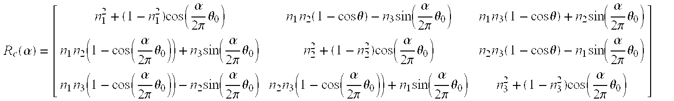
action 214, the computer compensates current pixel Pf (i.e., the selected pixel) with a rotational compensation matrix Rc matrix. The rotational compensation matrix Rc for pixel Pf can be used for all the pixels in the same column (e.g., all the pixels in selected column Q) to reduce the computational cost. Rotational compensation matrix Rc is the gross rotational matrix ΔR spread out among each of the columns oncylindrical surface 102. As unit directional vector n0 and rotational angle θ0 are calculated in action 206, then the compensation rotation matrix Rc can be defined as:
- Angle α (FIG. 4) is the rotation angle of current column Q in the XZ plane, which is determined by the arctangent of x 1/z1 of current pixel Pf.
- FIG. 5 shows that the computer traces the current pixel P f back to origin O to determine a ray OPf that passes through the current pixel Pf and a pixel Pc on the original stitched images. The computer then determines a ray OPf′ that would have been rotated by compensation matrix Rc(a) to coincide with ray OPf. The computer traces ray OPf′ to its intersection with the original stitched picture to find a pixel Po. The computer then paints the pixel color values of pixel Po to the current pixel Pf on the final stitched
images 102. - In
action 216, the computer determines if the current pixel Pf is the last pixel in the current column Q. If it is not,action 216 is followed byaction 218. If the current pixel Pf is the last pixel in the current column Q, thenaction 216 is followed byaction 220. - In
action 218, the computer selects a next pixel in the current column.Action 218 is followed byaction 214 and the above actions cycle until all the pixels in the current column have been compensated. - In
action 220, the computer determines if the current column in the last column oncylindrical surface 102. If it is not,action 220 is followed byaction 222. If the current column is the last column, thenaction 220 is followed byaction 224, which endsmethod 200. - In
action 222, the computer selects a next column oncylindrical surface 102.Action 222 is followed byaction 212 and the above actions cycle until all the pixels in all the columns have been compensated. - One embodiment of
method 200 implemented in pseudo code is provided in the attached index. - Various other adaptations and combinations of features of the embodiments disclosed are within the scope of the invention. Numerous embodiments are encompassed by the following claims.
Index for(x1 = count − 1; x1 > 0; x1 −−) { pR1 = &(pMatrix−>GetElement(x1 % count, 0)−>Rotate); *pR1 = pMatrix−>GetElement(x1 − 1, 0)−>RotateH; for(x2=count − 1; x2 > x1; x2−−) { pR2 = &(pMatrix−>GetElement(x2 % count, 0)−>Rotate); Mul(pR1, pR2, &R3); *pR2 = R3; } } pR1 = &(pMatrix−>GetElement(0, 0)−>Rotate); identity(pR1); double* A = new double[3 * 3]; pR1 = &(pMatrix−>GetElement(count − 1, 0)−>Rotate); pR2 = &(pMatrix−>GetElement(count − 1, 0)−>RotateH); Mul(pR1, pR2, &R3); *(A) = R3.r11; //A = inv(pR1); *(A+1) = R3.r21; *(A+2) = R3.r31; *(A+3) = R3.r12; *(A+4) = R3.r22; *(A+5) = R3.r32; *(A+6) = R3.r13; *(A+7) = R3.r23; *(A+8) = R3.r33; 3×3 orthogonal matrix “rotation axis” representation The following two functions implemented the conversion between an orthogonal matrix and it's “rotation axis” representation. //////////////////////////////////////////////// // // A unit orthogonal matrix(3×3) represented by the rotation axis and // the rotation angle // 1. [A]3×3 is the input unit orthogonal matrix; // 2. [n]3×1 is the output rotation axis; // 3. *pDegree is the output rotation angle; // 4. Return value is TRUE if success, // or else is TRUE. // //////////////////////////////////////////////// BOOL UOM2AxisAngle(double *A, double *n, double *pDegree) { const double PI = 3.1415926; double d1, d2, d3; d1 = *(A+4) + *(A+8) − 1.0; d2 = *(A) + *(A+8) − 1.0; d3= *(A) + *(A+4) − 1.0; if(*(A) < d1 ∥ *(A+4) < d2 ∥ *(A+8) < d3) { *n = 1.0; *(n+1) = 0.0; *(n+2) = 0.0; *pDegree = 0.0; return TRUE; } double trace, cs, ss; trace = MatrixTrace(A, 3); cs = (trace − 1.0)/2.0; if(cs == 1.0) { *n = 1.0; *(n+1) = 0.0; *(n+2) = 0.0; *pDegree = 0.0; } else if(cs == −1.0) { *n = 1.0; *(n+1) = 0.0; *(n+2) = 0.0; *pDegree = 3.14; } else { *pDegree = acos(cs); ss = sin(*pDegree); double temp = ss * 2.0; *n = (*(A+7) − *(A+5))/temp; //A(3, 2) − A(2, 3) *(n+1) = (*(A+2) − *(A+6))/temp; //A(1, 3) − A(3, 1) *(n+2) = (*(A+3) − *(A+1))/temp; //A(2, 1) − A(1, 2) } double norm = sqrt(*n * *n + *(n+1)* *(n+1) + *(n+2)* *(n+2)); *n = *n/norm; *(n+1) = *(n+1)/norm; *(n+2) = *(n+2)/norm; if((*pDegree > PI/4.0) ∥ (*pDegree <− PI/4.0)) *pDegree = 0.0; return TRUE; } //////////////////////////////////////////////// // // Using a rotation axis and a rotation angle can generate // a unit orthogonal matrix(3×3) // 1. [A]3×3 is the output unit orthogonal matrix; // 2. [n]3×1 is the input rotation axis, n should be a unit vector; // 3. degree is the input rotation angle. // //////////////////////////////////////////////// void AxisAngle2UOM(double *A, double *n, double degree) { double cs, ss, temp; double n11, n12, n13, n22, n23, n33; cs = cos(degree); ss = sin(degree); temp 1.0 − cs; n11 = *(n)* *(n); n12 = *(n)* *(n+1); n13 = *(n)* *(n+2); n22 = *(n+1)* *(n+1); n23 = *(n+1)* *(n+2); n33 = *(n+2)* *(n+2); *(A) = n11 * temp + cs; *(A+1) = n12 * temp − *(n+2) * ss; *(A+2) = n13 * temp + *(n+1) * ss; *(A+3) = n12 * temp + *(n+2) * ss; *(A+4) = n22 * temp + cs; *(A+5) = n23 * temp − *(n) * ss; *(A+6) = n13 * temp − *(n+1) * ss; *(A+7) = n23 * temp + *(n) * ss; *(A+8) = n33 * temp + cs; } Calculate the final stitch image layout In this step, we apply scan line technology to compute the final stitch image layout for the coming backward pixel-rendering algorithm. The layout datum is stored in the following structures. struct LineSegment { LONG e1; // start point LONG e2; // end point }; struct DLineSegment { double e1; // start degree double e2; // end degree }; class CScanRegion { public: // Region dimensions RECT rect; // Convenience points LineSegment* pSegH0; LineSegment* pSegV0; DLineSegment* pSegD0; protected: // Buffer headers LineSegment* pSegH; LineSegment* pSegV; DLineSegment* pSegD; public: CScanRegion( ); ˜CScanRegion( ); Create(RECT rcRegion); }; Compensate the current pixel with RC matrices LONG y_e1 = pScan[c].pSegV0[x].e1; LONG y_e2 = pScan[c].pSegV0[x].e2; double d_e1 = pScan[c].pSegD0[x].e1; double d_e2 = pScan[c].pSegD0[x].e2; double theta; if(fabs(d_e2 − d_e1) < 1.0e-2) theta = 0.0; else theta = (d_e2 − d_e1)/(y_e2 − y_e1); LONG x_wrap = x; for (y = y_e1; y <= y_e2; y++) { pict.x = x_wrap; pict.y = y; CartesianCoord cart1, cart2; Picture2Cartesian(&pict, &cart1); double* A = new double[3*3]; AxisAngle2UOM(A, pAxis d_e1 + (y − y_e1) * theta); if(fabs(Degree) > 1.0e-6) { double delta = (d_e1 + (y − y_e1) * theta)/Degree; cart2.x = pict.r * sin(delta * 2 * PI); cart2.z = −pict.r * cos(delta * 2 * PI); cart2.y = (cart1.y − *(A+3) * cart2.x − *(A+5) * cart2.z)/*(A+4); Cartesian2Picture(&cart2, &pict); } else { cart2.x = *A * cart1.x + *(A+3) * cart1.y + *(A+6) * cart1.z; cart2.y = *(A+1) * cart1.x + *(A+4) * cart1.y + *(A+7) * cart1.z; cart2.z = *(A+2) * cart1.x + *(A+5) * cart1.y + *(A+8) * cart1.z; Cartesian2Picture(&cart2, &pict); } delete [ ] A; } Picture2RealFilm(&pict, &film, R);
Claims (7)

Priority Applications (1)
| Application Number | Priority Date | Filing Date | Title |
|---|---|---|---|
| US10/230,786 US7400782B2 (en) | 2002-08-28 | 2002-08-28 | Image warping correction in forming 360 degree panoramic images |
Applications Claiming Priority (1)
| Application Number | Priority Date | Filing Date | Title |
|---|---|---|---|
| US10/230,786 US7400782B2 (en) | 2002-08-28 | 2002-08-28 | Image warping correction in forming 360 degree panoramic images |
Publications (2)
| Publication Number | Publication Date |
|---|---|
| US20040042685A1 true US20040042685A1 (en) | 2004-03-04 |
| US7400782B2 US7400782B2 (en) | 2008-07-15 |
Family
ID=31976582
Family Applications (1)
| Application Number | Title | Priority Date | Filing Date |
|---|---|---|---|
| US10/230,786 Expired - Lifetime US7400782B2 (en) | 2002-08-28 | 2002-08-28 | Image warping correction in forming 360 degree panoramic images |
Country Status (1)
| Country | Link |
|---|---|
| US (1) | US7400782B2 (en) |
Cited By (12)
| Publication number | Priority date | Publication date | Assignee | Title |
|---|---|---|---|---|
| US20090058991A1 (en) * | 2007-08-27 | 2009-03-05 | Soo-Kyun Kim | Method for photographing panoramic picture |
| US20140125761A1 (en) * | 2011-06-29 | 2014-05-08 | Panasonic Corporation | Image conversion apparatus, camera, image conversion method, and storage medium with program stored therein |
| US9398216B2 (en) * | 2012-06-06 | 2016-07-19 | Sony Corporation | Image processing apparatus, image processing method, and program |
| WO2018026951A1 (en) * | 2016-08-02 | 2018-02-08 | Parto Inc. | Rapid real-time large depth of field, whole body, multi-spectral optical imaging for skin surveillance and photography |
| US20180095533A1 (en) * | 2016-09-30 | 2018-04-05 | Samsung Electronics Co., Ltd. | Method for displaying an image and an electronic device thereof |
| US10156900B2 (en) * | 2014-05-09 | 2018-12-18 | Google Llc | Systems and methods for discerning eye signals and continuous biometric identification |
| US20190281319A1 (en) * | 2016-09-30 | 2019-09-12 | Interdigital Vc Holdings, Inc. | Method and apparatus for rectified motion compensation for omnidirectional videos |
| US20190306422A1 (en) * | 2018-04-02 | 2019-10-03 | Samsung Electronics Co., Ltd. | Method and system for handling 360 degree image content |
| CN112991178A (en) * | 2021-03-24 | 2021-06-18 | 北京百度网讯科技有限公司 | Image splicing method, device, equipment and medium |
| CN113658054A (en) * | 2021-07-06 | 2021-11-16 | 北京空间机电研究所 | Infrared image splicing correction method based on temperature drift characteristic line approximation |
| CN114007014A (en) * | 2021-10-29 | 2022-02-01 | 北京环境特性研究所 | Method and device for generating panoramic image, electronic equipment and storage medium |
| WO2022127875A1 (en) * | 2020-12-16 | 2022-06-23 | 影石创新科技股份有限公司 | Image splicing method, computer-readable storage medium, and computer device |
Families Citing this family (24)
| Publication number | Priority date | Publication date | Assignee | Title |
|---|---|---|---|---|
| JP4293053B2 (en) * | 2004-05-19 | 2009-07-08 | ソニー株式会社 | Imaging apparatus and method |
| US7782374B2 (en) * | 2005-03-03 | 2010-08-24 | Nissan Motor Co., Ltd. | Processor and processing method for generating a panoramic image for a vehicle |
| JP4715334B2 (en) * | 2005-06-24 | 2011-07-06 | 日産自動車株式会社 | Vehicular image generation apparatus and method |
| TWI303782B (en) * | 2006-03-10 | 2008-12-01 | Sony Taiwan Ltd | An optimized video stitching mehtod for asic implementation |
| US8073259B1 (en) * | 2007-08-22 | 2011-12-06 | Adobe Systems Incorporated | Method and apparatus for image feature matching in automatic image stitching |
| US9380292B2 (en) | 2009-07-31 | 2016-06-28 | 3Dmedia Corporation | Methods, systems, and computer-readable storage media for generating three-dimensional (3D) images of a scene |
| WO2011014419A1 (en) | 2009-07-31 | 2011-02-03 | 3Dmedia Corporation | Methods, systems, and computer-readable storage media for creating three-dimensional (3d) images of a scene |
| US20110025830A1 (en) | 2009-07-31 | 2011-02-03 | 3Dmedia Corporation | Methods, systems, and computer-readable storage media for generating stereoscopic content via depth map creation |
| KR101631912B1 (en) * | 2009-11-03 | 2016-06-20 | 엘지전자 주식회사 | Mobile terminal and control method thereof |
| US10080006B2 (en) * | 2009-12-11 | 2018-09-18 | Fotonation Limited | Stereoscopic (3D) panorama creation on handheld device |
| US20110141225A1 (en) * | 2009-12-11 | 2011-06-16 | Fotonation Ireland Limited | Panorama Imaging Based on Low-Res Images |
| US20110141224A1 (en) * | 2009-12-11 | 2011-06-16 | Fotonation Ireland Limited | Panorama Imaging Using Lo-Res Images |
| US20110141229A1 (en) * | 2009-12-11 | 2011-06-16 | Fotonation Ireland Limited | Panorama imaging using super-resolution |
| US20110141226A1 (en) * | 2009-12-11 | 2011-06-16 | Fotonation Ireland Limited | Panorama imaging based on a lo-res map |
| US8294748B2 (en) * | 2009-12-11 | 2012-10-23 | DigitalOptics Corporation Europe Limited | Panorama imaging using a blending map |
| US9344701B2 (en) | 2010-07-23 | 2016-05-17 | 3Dmedia Corporation | Methods, systems, and computer-readable storage media for identifying a rough depth map in a scene and for determining a stereo-base distance for three-dimensional (3D) content creation |
| US8983230B2 (en) * | 2010-07-26 | 2015-03-17 | Siemens Corporation | Global error minimization in image mosaicking using graph laplacians and its applications in microscopy |
| WO2012061549A2 (en) | 2010-11-03 | 2012-05-10 | 3Dmedia Corporation | Methods, systems, and computer program products for creating three-dimensional video sequences |
| US8274552B2 (en) | 2010-12-27 | 2012-09-25 | 3Dmedia Corporation | Primary and auxiliary image capture devices for image processing and related methods |
| US10200671B2 (en) | 2010-12-27 | 2019-02-05 | 3Dmedia Corporation | Primary and auxiliary image capture devices for image processing and related methods |
| US8818101B1 (en) * | 2012-01-03 | 2014-08-26 | Google Inc. | Apparatus and method for feature matching in distorted images |
| US20160054900A1 (en) * | 2014-08-25 | 2016-02-25 | Chuck Surack | Computer Implemented System and Method for Producing 360 Degree Perspective Images |
| US10085006B2 (en) * | 2016-09-08 | 2018-09-25 | Samsung Electronics Co., Ltd. | Three hundred sixty degree video stitching |
| CN108733211B (en) * | 2017-04-21 | 2020-05-22 | 宏达国际电子股份有限公司 | Tracking system, operation method thereof, controller and computer readable recording medium |
Citations (33)
| Publication number | Priority date | Publication date | Assignee | Title |
|---|---|---|---|---|
| US4090174A (en) * | 1976-11-01 | 1978-05-16 | International Business Machines Corporation | Method and apparatus for accessing horizontal sequences, vertical sequences and rectangular subarrays from an array stored in a modified word organized random access memory system |
| US4183162A (en) * | 1977-05-17 | 1980-01-15 | Barkley Studios, Inc. | Panoramic photograph album, and method for making the same |
| US4197004A (en) * | 1978-06-06 | 1980-04-08 | News Log International, Incorporated | Scrolling microfiche and method of producing the same |
| US5450604A (en) * | 1992-12-18 | 1995-09-12 | Xerox Corporation | Data rotation using parallel to serial units that receive data from memory units and rotation buffer that provides rotated data to memory units |
| US5742710A (en) * | 1994-02-23 | 1998-04-21 | Rca Thomson Licensing Corporation | Computationally-efficient method for estimating image motion |
| US5790206A (en) * | 1994-09-02 | 1998-08-04 | David Sarnoff Research Center, Inc. | Method and apparatus for global-to-local block motion estimation |
| US5987164A (en) * | 1997-08-01 | 1999-11-16 | Microsoft Corporation | Block adjustment method and apparatus for construction of image mosaics |
| US6078701A (en) * | 1997-08-01 | 2000-06-20 | Sarnoff Corporation | Method and apparatus for performing local to global multiframe alignment to construct mosaic images |
| US6097854A (en) * | 1997-08-01 | 2000-08-01 | Microsoft Corporation | Image mosaic construction system and apparatus with patch-based alignment, global block adjustment and pair-wise motion-based local warping |
| US6128108A (en) * | 1997-09-03 | 2000-10-03 | Mgi Software Corporation | Method and system for compositing images |
| US6157747A (en) * | 1997-08-01 | 2000-12-05 | Microsoft Corporation | 3-dimensional image rotation method and apparatus for producing image mosaics |
| US6192156B1 (en) * | 1998-04-03 | 2001-02-20 | Synapix, Inc. | Feature tracking using a dense feature array |
| US6249616B1 (en) * | 1997-05-30 | 2001-06-19 | Enroute, Inc | Combining digital images based on three-dimensional relationships between source image data sets |
| US20020006217A1 (en) * | 2000-04-28 | 2002-01-17 | Orametrix, Inc. | Methods for registration of three-dimensional frames to create three-dimensional virtual models of objects |
| US6359617B1 (en) * | 1998-09-25 | 2002-03-19 | Apple Computer, Inc. | Blending arbitrary overlaying images into panoramas |
| US6393162B1 (en) * | 1998-01-09 | 2002-05-21 | Olympus Optical Co., Ltd. | Image synthesizing apparatus |
| US6404516B1 (en) * | 1999-02-22 | 2002-06-11 | Applied Science Fiction, Inc. | Parametric image stitching |
| US6434265B1 (en) * | 1998-09-25 | 2002-08-13 | Apple Computers, Inc. | Aligning rectilinear images in 3D through projective registration and calibration |
| US6456323B1 (en) * | 1999-12-31 | 2002-09-24 | Stmicroelectronics, Inc. | Color correction estimation for panoramic digital camera |
| US20020181802A1 (en) * | 2001-05-03 | 2002-12-05 | John Peterson | Projecting images onto a surface |
| US20020191865A1 (en) * | 1998-11-13 | 2002-12-19 | Shingo Yamaguchi | Image manipulation for a digital copier which operates on a block basis |
| US6507665B1 (en) * | 1999-08-25 | 2003-01-14 | Eastman Kodak Company | Method for creating environment map containing information extracted from stereo image pairs |
| US6532037B1 (en) * | 1998-10-16 | 2003-03-11 | Olympus Optical Co., Ltd. | Camera system wherein recording medium in camera stores information on angle of view of photographing of image necessary for cylindrical conversion |
| US6587597B1 (en) * | 1999-01-21 | 2003-07-01 | Nec Corporation | Image input method, image input apparatus, and recording medium |
| US20030197780A1 (en) * | 2002-04-17 | 2003-10-23 | Osamu Iwaki | Method of recording image conversion parameters in annular images, and annular image data recorded with image conversion parameters |
| US6643413B1 (en) * | 2000-03-27 | 2003-11-04 | Microsoft Corporation | Manifold mosaic hopping for image-based rendering |
| US6646655B1 (en) * | 1999-03-09 | 2003-11-11 | Webex Communications, Inc. | Extracting a time-sequence of slides from video |
| US20030235344A1 (en) * | 2002-06-15 | 2003-12-25 | Kang Sing Bing | System and method deghosting mosaics using multiperspective plane sweep |
| US20050089244A1 (en) * | 2003-10-22 | 2005-04-28 | Arcsoft, Inc. | Panoramic maker engine for a low profile system |
| US6912325B2 (en) * | 2000-05-17 | 2005-06-28 | Eastman Kodak Company | Real time electronic registration of scanned documents |
| US6978051B2 (en) * | 2000-03-06 | 2005-12-20 | Sony Corporation | System and method for capturing adjacent images by utilizing a panorama mode |
| US7085435B2 (en) * | 1995-09-26 | 2006-08-01 | Canon Kabushiki Kaisha | Image synthesization method |
| US7194112B2 (en) * | 2001-03-12 | 2007-03-20 | Eastman Kodak Company | Three dimensional spatial panorama formation with a range imaging system |
Family Cites Families (1)
| Publication number | Priority date | Publication date | Assignee | Title |
|---|---|---|---|---|
| DE50313038D1 (en) | 2002-04-23 | 2010-10-14 | Palm Inc | SCAN TO GENERATE A TOTAL IMAGE BY CHECKING SUBSTITUTES OF A TEMPLATE |
-
2002
- 2002-08-28 US US10/230,786 patent/US7400782B2/en not_active Expired - Lifetime
Patent Citations (34)
| Publication number | Priority date | Publication date | Assignee | Title |
|---|---|---|---|---|
| US4090174A (en) * | 1976-11-01 | 1978-05-16 | International Business Machines Corporation | Method and apparatus for accessing horizontal sequences, vertical sequences and rectangular subarrays from an array stored in a modified word organized random access memory system |
| US4183162A (en) * | 1977-05-17 | 1980-01-15 | Barkley Studios, Inc. | Panoramic photograph album, and method for making the same |
| US4197004A (en) * | 1978-06-06 | 1980-04-08 | News Log International, Incorporated | Scrolling microfiche and method of producing the same |
| US5450604A (en) * | 1992-12-18 | 1995-09-12 | Xerox Corporation | Data rotation using parallel to serial units that receive data from memory units and rotation buffer that provides rotated data to memory units |
| US5742710A (en) * | 1994-02-23 | 1998-04-21 | Rca Thomson Licensing Corporation | Computationally-efficient method for estimating image motion |
| US5790206A (en) * | 1994-09-02 | 1998-08-04 | David Sarnoff Research Center, Inc. | Method and apparatus for global-to-local block motion estimation |
| US7085435B2 (en) * | 1995-09-26 | 2006-08-01 | Canon Kabushiki Kaisha | Image synthesization method |
| US6249616B1 (en) * | 1997-05-30 | 2001-06-19 | Enroute, Inc | Combining digital images based on three-dimensional relationships between source image data sets |
| US5987164A (en) * | 1997-08-01 | 1999-11-16 | Microsoft Corporation | Block adjustment method and apparatus for construction of image mosaics |
| US6157747A (en) * | 1997-08-01 | 2000-12-05 | Microsoft Corporation | 3-dimensional image rotation method and apparatus for producing image mosaics |
| US6097854A (en) * | 1997-08-01 | 2000-08-01 | Microsoft Corporation | Image mosaic construction system and apparatus with patch-based alignment, global block adjustment and pair-wise motion-based local warping |
| US6078701A (en) * | 1997-08-01 | 2000-06-20 | Sarnoff Corporation | Method and apparatus for performing local to global multiframe alignment to construct mosaic images |
| US6128108A (en) * | 1997-09-03 | 2000-10-03 | Mgi Software Corporation | Method and system for compositing images |
| US6385349B1 (en) * | 1997-09-03 | 2002-05-07 | Mgi Software Corporation | Method and system for compositing images |
| US6393162B1 (en) * | 1998-01-09 | 2002-05-21 | Olympus Optical Co., Ltd. | Image synthesizing apparatus |
| US6192156B1 (en) * | 1998-04-03 | 2001-02-20 | Synapix, Inc. | Feature tracking using a dense feature array |
| US6434265B1 (en) * | 1998-09-25 | 2002-08-13 | Apple Computers, Inc. | Aligning rectilinear images in 3D through projective registration and calibration |
| US6359617B1 (en) * | 1998-09-25 | 2002-03-19 | Apple Computer, Inc. | Blending arbitrary overlaying images into panoramas |
| US6532037B1 (en) * | 1998-10-16 | 2003-03-11 | Olympus Optical Co., Ltd. | Camera system wherein recording medium in camera stores information on angle of view of photographing of image necessary for cylindrical conversion |
| US20020191865A1 (en) * | 1998-11-13 | 2002-12-19 | Shingo Yamaguchi | Image manipulation for a digital copier which operates on a block basis |
| US6587597B1 (en) * | 1999-01-21 | 2003-07-01 | Nec Corporation | Image input method, image input apparatus, and recording medium |
| US6404516B1 (en) * | 1999-02-22 | 2002-06-11 | Applied Science Fiction, Inc. | Parametric image stitching |
| US6646655B1 (en) * | 1999-03-09 | 2003-11-11 | Webex Communications, Inc. | Extracting a time-sequence of slides from video |
| US6507665B1 (en) * | 1999-08-25 | 2003-01-14 | Eastman Kodak Company | Method for creating environment map containing information extracted from stereo image pairs |
| US6456323B1 (en) * | 1999-12-31 | 2002-09-24 | Stmicroelectronics, Inc. | Color correction estimation for panoramic digital camera |
| US6978051B2 (en) * | 2000-03-06 | 2005-12-20 | Sony Corporation | System and method for capturing adjacent images by utilizing a panorama mode |
| US6643413B1 (en) * | 2000-03-27 | 2003-11-04 | Microsoft Corporation | Manifold mosaic hopping for image-based rendering |
| US20020006217A1 (en) * | 2000-04-28 | 2002-01-17 | Orametrix, Inc. | Methods for registration of three-dimensional frames to create three-dimensional virtual models of objects |
| US6912325B2 (en) * | 2000-05-17 | 2005-06-28 | Eastman Kodak Company | Real time electronic registration of scanned documents |
| US7194112B2 (en) * | 2001-03-12 | 2007-03-20 | Eastman Kodak Company | Three dimensional spatial panorama formation with a range imaging system |
| US20020181802A1 (en) * | 2001-05-03 | 2002-12-05 | John Peterson | Projecting images onto a surface |
| US20030197780A1 (en) * | 2002-04-17 | 2003-10-23 | Osamu Iwaki | Method of recording image conversion parameters in annular images, and annular image data recorded with image conversion parameters |
| US20030235344A1 (en) * | 2002-06-15 | 2003-12-25 | Kang Sing Bing | System and method deghosting mosaics using multiperspective plane sweep |
| US20050089244A1 (en) * | 2003-10-22 | 2005-04-28 | Arcsoft, Inc. | Panoramic maker engine for a low profile system |
Cited By (21)
| Publication number | Priority date | Publication date | Assignee | Title |
|---|---|---|---|---|
| US8217989B2 (en) * | 2007-08-27 | 2012-07-10 | Samsung Electronics Co., Ltd. | Method for photographing panoramic picture |
| US20090058991A1 (en) * | 2007-08-27 | 2009-03-05 | Soo-Kyun Kim | Method for photographing panoramic picture |
| US20140125761A1 (en) * | 2011-06-29 | 2014-05-08 | Panasonic Corporation | Image conversion apparatus, camera, image conversion method, and storage medium with program stored therein |
| US9667864B2 (en) * | 2011-06-29 | 2017-05-30 | Panasonic Intellectual Property Management Co., Ltd. | Image conversion apparatus, camera, image conversion method, and storage medium with program stored therein |
| US10986268B2 (en) | 2012-06-06 | 2021-04-20 | Sony Corporation | Image processing apparatus, image processing method, and program |
| US9398216B2 (en) * | 2012-06-06 | 2016-07-19 | Sony Corporation | Image processing apparatus, image processing method, and program |
| US11711618B2 (en) | 2012-06-06 | 2023-07-25 | Sony Group Corporation | Image processing apparatus, image processing method, and program |
| US11039068B2 (en) | 2012-06-06 | 2021-06-15 | Sony Group Corporation | Image processing apparatus, image processing method, and program |
| US10999502B2 (en) | 2012-06-06 | 2021-05-04 | Sony Corporation | Image processing apparatus, image processing method, and program |
| US10156900B2 (en) * | 2014-05-09 | 2018-12-18 | Google Llc | Systems and methods for discerning eye signals and continuous biometric identification |
| WO2018026951A1 (en) * | 2016-08-02 | 2018-02-08 | Parto Inc. | Rapid real-time large depth of field, whole body, multi-spectral optical imaging for skin surveillance and photography |
| US10880488B2 (en) | 2016-08-02 | 2020-12-29 | Parto Inc. | Rapid real-time large depth of field, whole body, multi-spectral optical imaging for skin surveillance and photography |
| US20190281319A1 (en) * | 2016-09-30 | 2019-09-12 | Interdigital Vc Holdings, Inc. | Method and apparatus for rectified motion compensation for omnidirectional videos |
| US10401955B2 (en) * | 2016-09-30 | 2019-09-03 | Samsung Electronics Co., Ltd. | Method for displaying an image and an electronic device thereof |
| US20180095533A1 (en) * | 2016-09-30 | 2018-04-05 | Samsung Electronics Co., Ltd. | Method for displaying an image and an electronic device thereof |
| US10715725B2 (en) * | 2018-04-02 | 2020-07-14 | Samsung Electronics Co., Ltd | Method and system for handling 360 degree image content |
| US20190306422A1 (en) * | 2018-04-02 | 2019-10-03 | Samsung Electronics Co., Ltd. | Method and system for handling 360 degree image content |
| WO2022127875A1 (en) * | 2020-12-16 | 2022-06-23 | 影石创新科技股份有限公司 | Image splicing method, computer-readable storage medium, and computer device |
| CN112991178A (en) * | 2021-03-24 | 2021-06-18 | 北京百度网讯科技有限公司 | Image splicing method, device, equipment and medium |
| CN113658054A (en) * | 2021-07-06 | 2021-11-16 | 北京空间机电研究所 | Infrared image splicing correction method based on temperature drift characteristic line approximation |
| CN114007014A (en) * | 2021-10-29 | 2022-02-01 | 北京环境特性研究所 | Method and device for generating panoramic image, electronic equipment and storage medium |
Also Published As
| Publication number | Publication date |
|---|---|
| US7400782B2 (en) | 2008-07-15 |
Similar Documents
| Publication | Publication Date | Title |
|---|---|---|
| US7400782B2 (en) | Image warping correction in forming 360 degree panoramic images | |
| EP1676236B1 (en) | Panoramic maker engine for a low profile system | |
| US10187586B2 (en) | Image generation apparatus and method for generating plurality of images with different resolution and/or brightness from single image | |
| US8345961B2 (en) | Image stitching method and apparatus | |
| US8249390B2 (en) | Method for taking panorama mosaic photograph with a portable terminal | |
| KR101003277B1 (en) | Method and system for producing seamless composite images having non-uniform resolution from a multi-imager | |
| US7873207B2 (en) | Image processing apparatus and image processing program for multi-viewpoint image | |
| KR100893463B1 (en) | Methods and systems for producing seamless composite images without requiring overlap of source images | |
| US7224392B2 (en) | Electronic imaging system having a sensor for correcting perspective projection distortion | |
| US20060072851A1 (en) | Deghosting mosaics using multiperspective plane sweep | |
| CN104104887A (en) | A method and apparatus for applying a border to an image | |
| JP2007164258A (en) | Image synthesizing device and method | |
| JP7196421B2 (en) | Information processing device, information processing system, information processing method and program | |
| KR100614004B1 (en) | An automated method for creating 360 degrees panoramic image | |
| US6701030B1 (en) | Deghosting panoramic video | |
| JP2010130628A (en) | Imaging apparatus, image compositing device and image compositing method | |
| US20090059018A1 (en) | Navigation assisted mosaic photography | |
| JP2004135209A (en) | Generation device and method for wide-angle view high-resolution video image | |
| KR101801100B1 (en) | Video providing apparatus and method for supporting production of immersive contents | |
| TW201906398A (en) | Image capturing device and image mosaic method thereof | |
| JP4757679B2 (en) | Video composition device | |
| WO2013072166A1 (en) | Rectified stereoscopic 3d panoramic picture | |
| JP2006113001A (en) | Three-dimensional measuring method and device by photogrammetry | |
| JP4304997B2 (en) | Multi-camera video composition display device | |
| JP2013042213A (en) | Image processing device, image processing method, and program |
Legal Events
| Date | Code | Title | Description |
|---|---|---|---|
| AS | Assignment |
Owner name: ARCSOFT, INC., CALIFORNIA Free format text: ASSIGNMENT OF ASSIGNORS INTEREST;ASSIGNORS:ZHOU, LINGXIANG;HUANG, YUSHAN;REEL/FRAME:013601/0904;SIGNING DATES FROM 20021119 TO 20021203 |
|
| AS | Assignment |
Owner name: EAST WEST BANK,CALIFORNIA Free format text: SECURITY AGREEMENT;ASSIGNOR:ARCSOFT, INC.;REEL/FRAME:024218/0828 Effective date: 20100409 Owner name: EAST WEST BANK, CALIFORNIA Free format text: SECURITY AGREEMENT;ASSIGNOR:ARCSOFT, INC.;REEL/FRAME:024218/0828 Effective date: 20100409 |
|
| AS | Assignment |
Owner name: ARCSOFT, INC., CALIFORNIA Free format text: RELEASE BY SECURED PARTY;ASSIGNOR:EAST WEST BANK;REEL/FRAME:026616/0643 Effective date: 20110719 |
|
| REMI | Maintenance fee reminder mailed | ||
| LAPS | Lapse for failure to pay maintenance fees | ||
| FP | Lapsed due to failure to pay maintenance fee |
Effective date: 20120715 |
|
| AS | Assignment |
Owner name: EAST WEST BANK, CALIFORNIA Free format text: SECURITY INTEREST;ASSIGNORS:ARCSOFT, INC.;ARCSOFT (SHANGHAI) TECHNOLOGY CO., LTD.;ARCSOFT (HANGZHOU) MULTIMEDIA TECHNOLOGY CO., LTD.;AND OTHERS;REEL/FRAME:033535/0537 Effective date: 20140807 |
|
| AS | Assignment |
Owner name: ARCSOFT HANGZHOU CO., LTD., CALIFORNIA Free format text: RELEASE BY SECURED PARTY;ASSIGNOR:EAST WEST BANK;REEL/FRAME:037109/0027 Effective date: 20151111 Owner name: ARCSOFT, INC., CALIFORNIA Free format text: RELEASE BY SECURED PARTY;ASSIGNOR:EAST WEST BANK;REEL/FRAME:037109/0027 Effective date: 20151111 Owner name: MULTIMEDIA IMAGE SOLUTION LIMITED, CALIFORNIA Free format text: RELEASE BY SECURED PARTY;ASSIGNOR:EAST WEST BANK;REEL/FRAME:037109/0027 Effective date: 20151111 Owner name: ARCSOFT (SHANGHAI) TECHNOLOGY CO., LTD., CALIFORNI Free format text: RELEASE BY SECURED PARTY;ASSIGNOR:EAST WEST BANK;REEL/FRAME:037109/0027 Effective date: 20151111 Owner name: ARCSOFT (HANGZHOU) MULTIMEDIA TECHNOLOGY CO., LTD. Free format text: RELEASE BY SECURED PARTY;ASSIGNOR:EAST WEST BANK;REEL/FRAME:037109/0027 Effective date: 20151111 |
|
| FEPP | Fee payment procedure |
Free format text: PETITION RELATED TO MAINTENANCE FEES FILED (ORIGINAL EVENT CODE: PMFP); ENTITY STATUS OF PATENT OWNER: LARGE ENTITY |
|
| FEPP | Fee payment procedure |
Free format text: SURCHARGE, PETITION TO ACCEPT PYMT AFTER EXP, UNINTENTIONAL (ORIGINAL EVENT CODE: M1558) Free format text: PETITION RELATED TO MAINTENANCE FEES GRANTED (ORIGINAL EVENT CODE: PMFG) |
|
| MAFP | Maintenance fee payment |
Free format text: PAYMENT OF MAINTENANCE FEE, 8TH YEAR, LARGE ENTITY (ORIGINAL EVENT CODE: M1552) Year of fee payment: 8 Free format text: PAYMENT OF MAINTENANCE FEE, 4TH YEAR, LARGE ENTITY (ORIGINAL EVENT CODE: M1551) Year of fee payment: 4 |
|
| PRDP | Patent reinstated due to the acceptance of a late maintenance fee |
Effective date: 20170911 |
|
| STCF | Information on status: patent grant |
Free format text: PATENTED CASE |
|
| FEPP | Fee payment procedure |
Free format text: MAINTENANCE FEE REMINDER MAILED (ORIGINAL EVENT CODE: REM.); ENTITY STATUS OF PATENT OWNER: LARGE ENTITY |
|
| FEPP | Fee payment procedure |
Free format text: 11.5 YR SURCHARGE- LATE PMT W/IN 6 MO, LARGE ENTITY (ORIGINAL EVENT CODE: M1556); ENTITY STATUS OF PATENT OWNER: LARGE ENTITY |
|
| MAFP | Maintenance fee payment |
Free format text: PAYMENT OF MAINTENANCE FEE, 12TH YEAR, LARGE ENTITY (ORIGINAL EVENT CODE: M1553); ENTITY STATUS OF PATENT OWNER: LARGE ENTITY Year of fee payment: 12 |