US20040001527A1 - Circuit for sensing on-die temperature at multiple locations - Google Patents
Circuit for sensing on-die temperature at multiple locations Download PDFInfo
- Publication number
- US20040001527A1 US20040001527A1 US10/184,534 US18453402A US2004001527A1 US 20040001527 A1 US20040001527 A1 US 20040001527A1 US 18453402 A US18453402 A US 18453402A US 2004001527 A1 US2004001527 A1 US 2004001527A1
- Authority
- US
- United States
- Prior art keywords
- diode
- terminal
- coupled
- temperature
- circuit
- Prior art date
- Legal status (The legal status is an assumption and is not a legal conclusion. Google has not performed a legal analysis and makes no representation as to the accuracy of the status listed.)
- Granted
Links
- 238000000034 method Methods 0.000 claims description 11
- 238000004806 packaging method and process Methods 0.000 claims description 3
- 238000009529 body temperature measurement Methods 0.000 claims description 2
- 238000005259 measurement Methods 0.000 abstract description 5
- 238000013461 design Methods 0.000 description 3
- RYGMFSIKBFXOCR-UHFFFAOYSA-N Copper Chemical compound [Cu] RYGMFSIKBFXOCR-UHFFFAOYSA-N 0.000 description 2
- XUIMIQQOPSSXEZ-UHFFFAOYSA-N Silicon Chemical compound [Si] XUIMIQQOPSSXEZ-UHFFFAOYSA-N 0.000 description 2
- XAGFODPZIPBFFR-UHFFFAOYSA-N aluminium Chemical compound [Al] XAGFODPZIPBFFR-UHFFFAOYSA-N 0.000 description 2
- 229910052782 aluminium Inorganic materials 0.000 description 2
- 229910052802 copper Inorganic materials 0.000 description 2
- 239000010949 copper Substances 0.000 description 2
- 229910052710 silicon Inorganic materials 0.000 description 2
- 239000010703 silicon Substances 0.000 description 2
- 239000013078 crystal Substances 0.000 description 1
- 230000000694 effects Effects 0.000 description 1
- 239000000463 material Substances 0.000 description 1
- 238000012986 modification Methods 0.000 description 1
- 230000004048 modification Effects 0.000 description 1
- 238000013021 overheating Methods 0.000 description 1
- 230000000135 prohibitive effect Effects 0.000 description 1
- 230000006903 response to temperature Effects 0.000 description 1
- 239000004065 semiconductor Substances 0.000 description 1
- 238000002791 soaking Methods 0.000 description 1
- 238000010561 standard procedure Methods 0.000 description 1
- 239000000126 substance Substances 0.000 description 1
- 239000000758 substrate Substances 0.000 description 1
Images


Classifications
-
- G—PHYSICS
- G01—MEASURING; TESTING
- G01K—MEASURING TEMPERATURE; MEASURING QUANTITY OF HEAT; THERMALLY-SENSITIVE ELEMENTS NOT OTHERWISE PROVIDED FOR
- G01K7/00—Measuring temperature based on the use of electric or magnetic elements directly sensitive to heat ; Power supply therefor, e.g. using thermoelectric elements
- G01K7/01—Measuring temperature based on the use of electric or magnetic elements directly sensitive to heat ; Power supply therefor, e.g. using thermoelectric elements using semiconducting elements having PN junctions
Definitions
- the present invention pertains to the field of integrated circuit design. More particularly, the present invention relates to a circuit for sensing temperature at multiple locations on a silicon die using a minimum number of integrated circuit terminals.
- Thermal diodes are typically the base-emitter junction of a substrate connected PNP transistor. This junction may be modeled using the ideal diode equation.
- the terminals of the diode are coupled to IC terminals.
- the voltage drop v across the diode is measured at the terminals.
- the IC may or may not be running.
- FIG. 1 is one embodiment of a circuit for sensing on die temperature at multiple locations
- FIG. 3 is a flowchart for calculating the temperature at a die location.
- a diode has an anode terminal and a cathode terminal. Current flows primarily from the anode terminal of the diode to the cathode terminal.
- FIG. 1 depicts one embodiment of the invention.
- the circuit of FIG. 1 has six diodes ( 101 - 106 ) and three IC terminals ( 121 - 123 ).
- the IC terminals 121 - 123 may be implemented as bumps or pins.
- Diodes 101 and 102 are coupled to IC terminals 121 and 122 .
- Diodes 103 and 104 are coupled to IC terminals 122 and 123 .
- Diodes 105 and 106 are coupled to IC terminals 121 and 123 .
- Each of the diodes 101 - 106 has an anode terminal, a cathode terminal, and a clamping voltage of approximately 0.7 volts (V).
- V 0.7 volts
- diodes 102 and 104 will also be forward biased. However, because only 0.7 volts is applied across IC terminals 121 and 123 , the forward biased current traveling through diodes 102 and 104 are orders of magnitude less than the current traveling through diode 106 . As a result, the current measured across the IC terminals 121 and 123 will predominately reflect the forward biased current traveling through diode 106 . From the current measurement, the temperature at diode 106 may be calculated. The temperature calculation process is depicted in FIG. 3 and described below.
- D is the number of diodes and N is the number of IC terminals.
- FIG. 2 depicts one embodiment of a system that uses thermal diodes to prevent an IC from overheating.
- IC 100 has a plurality of diodes distributed throughout the chip to measure temperatures.
- Signals 210 and 220 are diode measurements obtained from IC 100 .
- a temperature sensing circuit 230 is coupled to integrated circuit 100 and calculates temperatures based upon signals 210 and 220 . If the calculated temperature is greater than a predetermined threshold value, the temperature sensing circuit 230 reduces the power of integrated circuit 100 .
- the temperature sensing circuit 230 is manufactured on the same die as integrated circuit 100 .
- a process for calculating IC temperatures is depicted in FIG. 3.
- operation 310 a plurality of diodes is placed on an IC to determine temperatures of the IC.
- the number of diodes on the IC may be approximately equal to n*(n ⁇ 1), where n is the number of IC terminals.
- the resistance of copper and aluminum wires vary with temperature.
- the relationship of the trace resistivity and its corresponding temperature may be defined by a curve.
- This curve may have a known series resistance value R s0 at a temperature T 0 , a known series resistance value ⁇ 0 at 0 Kelvin, and a slope M.
- a known current i 1 is sent through a diode on the IC in operation 330 .
- the current is sent through the diode through an IC terminal and allowed to return via another IC terminal.
- the selected diode is determined by which IC terminal the current is sourced since current will not conduct across a reverse biased diode.
- the voltage drop v 1 is then measured across the diode's terminals in operation 340 .
- a second set of current and voltage values, i 2 and v 2 may then be obtained.
- Equation 12 compensates for effective series resistance and effective series resistance changes due to thermal variation. Note that the values v 1 and v 2 were obtained based on i 1 and i 2 inputs. The values for R 0 , T 0 , ⁇ 0 , and M were obtained during the series resistance calibration of operation 320 . By substituting these values into equation 12, the temperature T of the diode may be calculated.
- operation 360 determines whether there are further temperature measurement requests. If there are further measurement requests, a first known current and a second known current are sent through another diode in operation 330 , the voltage is measured across the diode's terminals in operation 340 , and the temperature is calculated in operation 350 . Otherwise, the process is terminated in operation 370 .
Landscapes
- Physics & Mathematics (AREA)
- General Physics & Mathematics (AREA)
- Measuring Temperature Or Quantity Of Heat (AREA)
Abstract
Description
- The present invention pertains to the field of integrated circuit design. More particularly, the present invention relates to a circuit for sensing temperature at multiple locations on a silicon die using a minimum number of integrated circuit terminals.
- An integrated circuit (IC) is a device consisting of a number of connected circuit elements, such as transistors and resistors, fabricated on a single chip of silicon crystal or other semiconductor material. During operation, an IC burns power causing the temperature of the IC to increase. An overheated IC can potentially result in reduced performance and even failure.
- ICs, however, are typically packaged in such a way that it is difficult to directly measure the temperature at the active part of the die using a thermocouple or other external measuring device. As a result, the standard method for measuring the die temperature of an IC is to incorporate a thermal diode with known thermal characteristics into the design of the IC.
- Thermal diodes are typically the base-emitter junction of a substrate connected PNP transistor. This junction may be modeled using the ideal diode equation. The equation of an ideal diode is:

- where i is the forward biased current through the diode, I s is the saturation current of the diode, v is the voltage drop across the diode, q is the charge of an electron, n is an ideality factor, k is Boltzmann's Constant, and T is the temperature in Kelvin. The ideality factor n is constant for a given process technology. A range for this number is typically available in its product data sheet.
- To measure the die temperature using a diode, the terminals of the diode are coupled to IC terminals. By applying a current i to the diode, the voltage drop v across the diode is measured at the terminals. For this measurement, the IC may or may not be running. By measuring the voltage drop at two different currents, i 1 and i2, at constant temperature T, the value Is is cancelled out as shown in the equation:

- Equation 2 may be simplified by removing the 1's since they are negligible. Thus, the equation becomes:

- Given that the ratio of the currents is constant, the temperature is directly proportional to the difference in the two measured voltage drops, v 1 and v2:

- Solving for T:

- Equation 4, however, does not include the effective series resistance, R s, of the diode. Typically, long traces are a primary source of effective series resistance. Placing the diode near IC terminals would help to reduce series resistance. In reality, however, the diode is often a distance from the IC terminals due to area constraints. Because the effective series resistance may be substantial in an IC such as a microprocessor, it would be desirable to include its effects in the temperature calculation.
- In addition, as the trend in IC design continues toward smaller chips, the power density increases and becomes less uniform. This causes the thermal gradients across the die to become greater. As a result, even though previous ICs were able to suffice with a single thermal diode at a single location on the die, future ICs may require multiple thermal diodes in order to map out the thermal profile in better detail.
- Because IC terminals are at a premium on chips, the addition of thermal diodes beyond the first one may be cost prohibitive. Therefore, it would be desirable for a circuit to allow for the placement of multiple thermal diodes on the die while minimizing the number of IC terminals used.
- The embodiments of the present invention are illustrated by way of example and not in the figures of the accompanying drawings, in which like references indicate similar elements and in which:
- FIG. 1 is one embodiment of a circuit for sensing on die temperature at multiple locations;
- FIG. 2 is one embodiment of a system that measures die temperatures; and
- FIG. 3 is a flowchart for calculating the temperature at a die location.
- In the following detailed description, numerous specific details are set forth in order to provide a thorough understanding of the invention. However, it will be understood by those skilled in the art that the present invention may be practiced without these specific details. In other instances, well-known methods, procedures, components and circuits have not been described in detail so as not to obscure the present invention.
- The use of multiple thermal diodes allow for the determination of thermal gradients on an IC. Multiple diodes may be used to measure die temperature without having to use two times the number of IC terminals per diode by taking advantage of the diodes' electrical properties. A diode has an anode terminal and a cathode terminal. Current flows primarily from the anode terminal of the diode to the cathode terminal.
- Therefore, if two diodes having opposite polarity (terminals are flipped with respect to one another) are placed between two parallel conducting wires of differing voltages, current will only flow through the diode having its anode terminal connected to the wire having the higher voltage and its cathode terminal connected to the wire having the lower voltage. The other diode will not conduct because it will be reverse biased. Because the leakage current of the reverse biased diode is substantially smaller than the current passing through the forward biased diode, the leakage current is negligible.
- Taking advantage of this theory, FIG. 1 depicts one embodiment of the invention. The circuit of FIG. 1 has six diodes ( 101-106) and three IC terminals (121-123). Depending on the packaging used, the IC terminals 121-123 may be implemented as bumps or pins.
Diodes IC terminals Diodes IC terminals Diodes IC terminals - Each of the diodes 101-106 has an anode terminal, a cathode terminal, and a clamping voltage of approximately 0.7 volts (V). When two voltages are applied to a diode such that the cathode terminal is coupled to a higher voltage than the anode terminal, a forward biased current is generated across that diode.
- As an example, if 0.7 V is applied to
IC terminal 121, 0 V is applied toIC terminal 123, andIC terminal 122 is left in a high impedance state such that no current flows into or out ofIC terminal 122, a forward biased current will flow throughdiode 106. Becausediode 105 has the opposite polarity asdiode 106,diode 105 is reverse biased. Thus, no current will flow acrossdiode 105. - Note that
diodes IC terminals diodes diode 106. As a result, the current measured across theIC terminals diode 106. From the current measurement, the temperature atdiode 106 may be calculated. The temperature calculation process is depicted in FIG. 3 and described below. - From FIG. 1 and the example above, it can be seen that a pair of diodes having opposite polarity may be placed between each set of IC terminals. Specifically, the number of diodes that may be used on an IC may be defined by the equation:
- D=N*(N−1) (equation 5)
- where D is the number of diodes and N is the number of IC terminals.
- FIG. 2 depicts one embodiment of a system that uses thermal diodes to prevent an IC from overheating. For this embodiment of the invention,
IC 100 has a plurality of diodes distributed throughout the chip to measure temperatures.Signals IC 100. Atemperature sensing circuit 230 is coupled tointegrated circuit 100 and calculates temperatures based uponsignals temperature sensing circuit 230 reduces the power ofintegrated circuit 100. - For another embodiment of the invention, the
temperature sensing circuit 230 is manufactured on the same die asintegrated circuit 100. - A process for calculating IC temperatures is depicted in FIG. 3. In
operation 310, a plurality of diodes is placed on an IC to determine temperatures of the IC. The number of diodes on the IC may be approximately equal to n*(n−1), where n is the number of IC terminals. - In
operation 320, the diodes are calibrated to determine their electrical characteristics across a range of possible operating temperatures. The calibration helps to determine voltage or current values that may be safely applied to a thermal diode. Calibration may be accomplished by soaking the die in a chemical bath at different temperatures. Moreover, the effective series resistance of the diode is also calibrated. As stated above, the effective series resistance of diodes may be caused by long traces. For one embodiment of the invention, the traces are copper wires. For another embodiment of the invention, the traces are aluminum wires. - The resistance of copper and aluminum wires vary with temperature. Thus, the relationship of the trace resistivity and its corresponding temperature may be defined by a curve. This curve may have a known series resistance value R s0 at a temperature T0, a known series resistance value ρ0 at 0 Kelvin, and a slope M. Series resistance Rs may be represented by:

- Following
operation 320, a known current i1 is sent through a diode on the IC inoperation 330. The current is sent through the diode through an IC terminal and allowed to return via another IC terminal. As previously discussed, it is possible to have two diodes having opposite polarity coupled between any two IC terminals. Thus, the selected diode is determined by which IC terminal the current is sourced since current will not conduct across a reverse biased diode. - The voltage drop v 1 is then measured across the diode's terminals in
operation 340. A second set of current and voltage values, i2 and v2, may then be obtained. To calculate the temperature of the diode inoperation 350, the voltage drop across the diode may be represented by:
- which includes the effective series resistance. Accordingly, the temperature equation of equation 4 may be rewritten as:
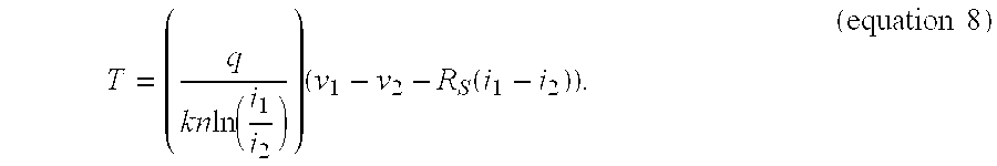
- Equation 8 assumes that the series resistance of the trace is approximately equal in temperature as the diode being measured. Equation 8 may be rewritten as:

- From equation 6, R s, may alternatively be represented by:

- The equation 10 can be substituted into equation 9 such that

- Resolve for T:

- Alternatively, equation 11 can be expressed as:

- Equation 12 compensates for effective series resistance and effective series resistance changes due to thermal variation. Note that the values v 1 and v2 were obtained based on i1 and i2 inputs. The values for R0, T0, ρ0, and M were obtained during the series resistance calibration of
operation 320. By substituting these values into equation 12, the temperature T of the diode may be calculated. - After the temperature calculation,
operation 360 determines whether there are further temperature measurement requests. If there are further measurement requests, a first known current and a second known current are sent through another diode inoperation 330, the voltage is measured across the diode's terminals inoperation 340, and the temperature is calculated inoperation 350. Otherwise, the process is terminated inoperation 370. - For another embodiment of the invention, only one known current is sent through a diode. The voltage is then measured and translated into a temperature by applying a linear approximation. The equation of the linear approximation may be determined by characterizing many parts to determine the average voltage response to temperature at a given current.
- For yet another embodiment of the invention, instead of sending a known current through a diode and measuring the voltage across the diode's terminals as in
operations operation 330 and the corresponding current is measured inoperation 340. The remaining operations of FIG. 3 remain the same. - In the foregoing specification the invention has been described with reference to specific exemplary embodiments thereof. It will, however, be evident that various modification and changes may be made thereto without departure from the broader spirit and scope of the invention as set forth in the appended claims. The specification and drawings are, accordingly, to be regarded in an illustrative rather than restrictive sense.
Claims (18)
Priority Applications (1)
| Application Number | Priority Date | Filing Date | Title |
|---|---|---|---|
| US10/184,534 US7018095B2 (en) | 2002-06-27 | 2002-06-27 | Circuit for sensing on-die temperature at multiple locations |
Applications Claiming Priority (1)
| Application Number | Priority Date | Filing Date | Title |
|---|---|---|---|
| US10/184,534 US7018095B2 (en) | 2002-06-27 | 2002-06-27 | Circuit for sensing on-die temperature at multiple locations |
Publications (2)
| Publication Number | Publication Date |
|---|---|
| US20040001527A1 true US20040001527A1 (en) | 2004-01-01 |
| US7018095B2 US7018095B2 (en) | 2006-03-28 |
Family
ID=29779389
Family Applications (1)
| Application Number | Title | Priority Date | Filing Date |
|---|---|---|---|
| US10/184,534 Expired - Fee Related US7018095B2 (en) | 2002-06-27 | 2002-06-27 | Circuit for sensing on-die temperature at multiple locations |
Country Status (1)
| Country | Link |
|---|---|
| US (1) | US7018095B2 (en) |
Cited By (9)
| Publication number | Priority date | Publication date | Assignee | Title |
|---|---|---|---|---|
| US20070210818A1 (en) * | 2006-03-09 | 2007-09-13 | International Business Machines Corporation | Temperature monitoring and control apparatus and method |
| US20080007319A1 (en) * | 2006-06-21 | 2008-01-10 | Cox Christopher E | Thermal sensor having toggle control |
| GB2440657A (en) * | 2006-08-01 | 2008-02-06 | Intel Corp | Dynamic power control of an on-die thermal sensor |
| EP2031758A1 (en) * | 2007-08-29 | 2009-03-04 | Yazaki Corporation | Protecting circuit |
| US7828479B1 (en) * | 2003-04-08 | 2010-11-09 | National Semiconductor Corporation | Three-terminal dual-diode system for fully differential remote temperature sensors |
| CN102299698A (en) * | 2009-10-09 | 2011-12-28 | 飞兆半导体公司 | High impedance bias network |
| US20130144549A1 (en) * | 2011-12-01 | 2013-06-06 | Grigori Temkine | Method for calibrating temperature sensors using reference voltages |
| WO2017052929A1 (en) * | 2015-09-25 | 2017-03-30 | Intel Corporation | Thermal sensor including pulse-width modulation output |
| US20190086272A1 (en) * | 2017-09-17 | 2019-03-21 | Qualcomm Incorporated | Diode-based temperature sensor |
Families Citing this family (7)
| Publication number | Priority date | Publication date | Assignee | Title |
|---|---|---|---|---|
| US7857510B2 (en) * | 2003-11-08 | 2010-12-28 | Carl F Liepold | Temperature sensing circuit |
| US20050099163A1 (en) * | 2003-11-08 | 2005-05-12 | Andigilog, Inc. | Temperature manager |
| US20060063285A1 (en) * | 2004-09-23 | 2006-03-23 | Miller Joseph P | Methods for measuring die temperature |
| US7113881B2 (en) * | 2004-11-04 | 2006-09-26 | International Business Machines Corporation | Method and apparatus for semi-automatic extraction and monitoring of diode ideality in a manufacturing environment |
| US20060203883A1 (en) * | 2005-03-08 | 2006-09-14 | Intel Corporation | Temperature sensing |
| US20080317086A1 (en) * | 2007-06-22 | 2008-12-25 | Santos Ishmael F | Self-calibrating digital thermal sensors |
| US8573841B2 (en) * | 2011-04-08 | 2013-11-05 | Advanced Micro Devices, Inc. | On-chip temperature sensor |
Citations (14)
| Publication number | Priority date | Publication date | Assignee | Title |
|---|---|---|---|---|
| US3330158A (en) * | 1965-07-12 | 1967-07-11 | Diode Corp Comp | Solid state temperature measuring device |
| US4050083A (en) * | 1976-09-22 | 1977-09-20 | Cutler-Hammer, Inc. | Integrated thermally sensitive power switching semiconductor device, including a thermally self-protected version |
| US4994688A (en) * | 1988-05-25 | 1991-02-19 | Hitachi Ltd. | Semiconductor device having a reference voltage generating circuit |
| US5154514A (en) * | 1991-08-29 | 1992-10-13 | International Business Machines Corporation | On-chip temperature sensor utilizing a Schottky barrier diode structure |
| US5440520A (en) * | 1994-09-16 | 1995-08-08 | Intel Corporation | Integrated circuit device that selects its own supply voltage by controlling a power supply |
| US5500547A (en) * | 1993-12-28 | 1996-03-19 | Nec Corporation | Integrated semiconductor device with temperature sensing circuit and method for operating same |
| US5751159A (en) * | 1995-09-05 | 1998-05-12 | Motorola, Inc. | Semiconductor array and switches formed on a common substrate for array testing purposes |
| US5949121A (en) * | 1996-08-02 | 1999-09-07 | Motorola Inc. | Temperature-indicating field effect transistor |
| US5990576A (en) * | 1994-01-14 | 1999-11-23 | Kabushiki Kaisha Toshiba | Power supply voltage supplying circuit |
| US6321175B1 (en) * | 1998-12-21 | 2001-11-20 | Intel Corporation | Thermal sensing of multiple integrated circuits |
| US6332710B1 (en) * | 2000-07-24 | 2001-12-25 | National Semiconductor Corporation | Multi-channel remote diode temperature sensor |
| US6580150B1 (en) * | 2000-11-13 | 2003-06-17 | Vram Technologies, Llc | Vertical junction field effect semiconductor diodes |
| US6612738B2 (en) * | 2000-03-08 | 2003-09-02 | Infineon Technologies | Method for determining the temperature of a semiconductor chip and semiconductor chip with temperature measuring configuration |
| US6674623B1 (en) * | 1999-12-02 | 2004-01-06 | Mitsubishi Denki Kabushiki Kaisha | Microcomputer equipped with built-in temperature sensor |
Family Cites Families (6)
| Publication number | Priority date | Publication date | Assignee | Title |
|---|---|---|---|---|
| US3440883A (en) * | 1966-12-01 | 1969-04-29 | Monsanto Co | Electronic semiconductor thermometer |
| US5100829A (en) * | 1989-08-22 | 1992-03-31 | Motorola, Inc. | Process for forming a semiconductor structure with closely coupled substrate temperature sense element |
| US5639163A (en) * | 1994-11-14 | 1997-06-17 | International Business Machines Corporation | On-chip temperature sensing system |
| DE19652046C2 (en) * | 1996-12-13 | 2003-08-28 | Infineon Technologies Ag | Method for determining the temperature of a semiconductor chip |
| US5961215A (en) * | 1997-09-26 | 1999-10-05 | Advanced Micro Devices, Inc. | Temperature sensor integral with microprocessor and methods of using same |
| TW380314B (en) * | 1998-01-23 | 2000-01-21 | United Microelectronics Corp | Bi-directional transistor device |
-
2002
- 2002-06-27 US US10/184,534 patent/US7018095B2/en not_active Expired - Fee Related
Patent Citations (14)
| Publication number | Priority date | Publication date | Assignee | Title |
|---|---|---|---|---|
| US3330158A (en) * | 1965-07-12 | 1967-07-11 | Diode Corp Comp | Solid state temperature measuring device |
| US4050083A (en) * | 1976-09-22 | 1977-09-20 | Cutler-Hammer, Inc. | Integrated thermally sensitive power switching semiconductor device, including a thermally self-protected version |
| US4994688A (en) * | 1988-05-25 | 1991-02-19 | Hitachi Ltd. | Semiconductor device having a reference voltage generating circuit |
| US5154514A (en) * | 1991-08-29 | 1992-10-13 | International Business Machines Corporation | On-chip temperature sensor utilizing a Schottky barrier diode structure |
| US5500547A (en) * | 1993-12-28 | 1996-03-19 | Nec Corporation | Integrated semiconductor device with temperature sensing circuit and method for operating same |
| US5990576A (en) * | 1994-01-14 | 1999-11-23 | Kabushiki Kaisha Toshiba | Power supply voltage supplying circuit |
| US5440520A (en) * | 1994-09-16 | 1995-08-08 | Intel Corporation | Integrated circuit device that selects its own supply voltage by controlling a power supply |
| US5751159A (en) * | 1995-09-05 | 1998-05-12 | Motorola, Inc. | Semiconductor array and switches formed on a common substrate for array testing purposes |
| US5949121A (en) * | 1996-08-02 | 1999-09-07 | Motorola Inc. | Temperature-indicating field effect transistor |
| US6321175B1 (en) * | 1998-12-21 | 2001-11-20 | Intel Corporation | Thermal sensing of multiple integrated circuits |
| US6674623B1 (en) * | 1999-12-02 | 2004-01-06 | Mitsubishi Denki Kabushiki Kaisha | Microcomputer equipped with built-in temperature sensor |
| US6612738B2 (en) * | 2000-03-08 | 2003-09-02 | Infineon Technologies | Method for determining the temperature of a semiconductor chip and semiconductor chip with temperature measuring configuration |
| US6332710B1 (en) * | 2000-07-24 | 2001-12-25 | National Semiconductor Corporation | Multi-channel remote diode temperature sensor |
| US6580150B1 (en) * | 2000-11-13 | 2003-06-17 | Vram Technologies, Llc | Vertical junction field effect semiconductor diodes |
Cited By (18)
| Publication number | Priority date | Publication date | Assignee | Title |
|---|---|---|---|---|
| US7828479B1 (en) * | 2003-04-08 | 2010-11-09 | National Semiconductor Corporation | Three-terminal dual-diode system for fully differential remote temperature sensors |
| US20070210818A1 (en) * | 2006-03-09 | 2007-09-13 | International Business Machines Corporation | Temperature monitoring and control apparatus and method |
| US8684597B2 (en) | 2006-06-21 | 2014-04-01 | Intel Corporation | Thermal sensor having toggle control |
| US20080007319A1 (en) * | 2006-06-21 | 2008-01-10 | Cox Christopher E | Thermal sensor having toggle control |
| US9714868B2 (en) | 2006-06-21 | 2017-07-25 | Intel Corporation | Thermal sensor having toggle control |
| CN101093715B (en) * | 2006-06-21 | 2012-02-29 | 英特尔公司 | Apparatus, method and system for thermal sensor with switching control |
| US8118483B2 (en) | 2006-06-21 | 2012-02-21 | Intel Corporation | Thermal sensor having toggle control |
| GB2440657B (en) * | 2006-08-01 | 2011-03-02 | Intel Corp | Dynamic Power Control of an On-Die Thermal Sensor |
| GB2440657A (en) * | 2006-08-01 | 2008-02-06 | Intel Corp | Dynamic power control of an on-die thermal sensor |
| US8272781B2 (en) | 2006-08-01 | 2012-09-25 | Intel Corporation | Dynamic power control of a memory device thermal sensor |
| US20080043556A1 (en) * | 2006-08-01 | 2008-02-21 | Nale William H | Dynamic power control of a memory device thermal sensor |
| EP2031758A1 (en) * | 2007-08-29 | 2009-03-04 | Yazaki Corporation | Protecting circuit |
| CN102299698A (en) * | 2009-10-09 | 2011-12-28 | 飞兆半导体公司 | High impedance bias network |
| US20130144549A1 (en) * | 2011-12-01 | 2013-06-06 | Grigori Temkine | Method for calibrating temperature sensors using reference voltages |
| WO2017052929A1 (en) * | 2015-09-25 | 2017-03-30 | Intel Corporation | Thermal sensor including pulse-width modulation output |
| US10866145B2 (en) | 2015-09-25 | 2020-12-15 | Intel IP Corporation | Thermal sensor including pulse-width modulation output |
| US20190086272A1 (en) * | 2017-09-17 | 2019-03-21 | Qualcomm Incorporated | Diode-based temperature sensor |
| US10578497B2 (en) * | 2017-09-17 | 2020-03-03 | Qualcomm Incorporated | Diode-based temperature sensor |
Also Published As
| Publication number | Publication date |
|---|---|
| US7018095B2 (en) | 2006-03-28 |
Similar Documents
| Publication | Publication Date | Title |
|---|---|---|
| US7018095B2 (en) | Circuit for sensing on-die temperature at multiple locations | |
| US9857247B2 (en) | Method and device for sensing isotropic stress and providing a compensation for the piezo-hall effect | |
| US11029338B2 (en) | Current sensor | |
| US7302357B2 (en) | Concept for compensating piezo-influences on an integrated semiconductor circuit | |
| US9016939B2 (en) | Thermal sensor with second-order temperature curvature correction | |
| US6786639B2 (en) | Device for sensing temperature of an electronic chip | |
| US7852148B2 (en) | Method of forming a sensing circuit and structure therefor | |
| JP2002289789A (en) | On-chip temperature detection device | |
| US6726361B2 (en) | Arrangement for measuring the temperature of an electronic circuit | |
| US7052179B2 (en) | Temperature detector | |
| US20060220012A1 (en) | Test key having a chain circuit and a kelvin structure | |
| CN112526425B (en) | Thermal resistance measuring instrument calibration method and device based on thermal resistance standard component | |
| US7859328B2 (en) | Substrate stress measuring technique | |
| EP4210220A1 (en) | Current sense circuit having a temperature compensated response | |
| US20070139034A1 (en) | Semiconductor Device and Testing Method Thereof, and Resistance Measurement Apparatus | |
| US9310261B2 (en) | Production-test die temperature measurement method and apparatus | |
| WO2022168156A1 (en) | Semiconductor equipment | |
| US20060063285A1 (en) | Methods for measuring die temperature | |
| JP2000039461A (en) | Measuring method for junction temperature of semiconductor integrated circuit and dut board using the measuring method | |
| US6903559B2 (en) | Method and apparatus to determine integrated circuit temperature | |
| US20240110839A1 (en) | Semiconductor circuit arrangement and method for a semiconductor circuit arrangement | |
| US12287364B2 (en) | Test system and test device | |
| US11367831B2 (en) | Semiconductor device | |
| US20050179035A1 (en) | Apparatus and method to access a plurality of pn-junctions with a limited number of pins | |
| Glavanovics et al. | Indirect In-Situ Junction Temperature Measurement for Condition Monitoring of GaN HEMT Devices during Application Related Reliability Testing |
Legal Events
| Date | Code | Title | Description |
|---|---|---|---|
| AS | Assignment |
Owner name: INTEL CORPORATION, CALIFORNIA Free format text: ASSIGNMENT OF ASSIGNORS INTEREST;ASSIGNORS:GRANNES, DEAN J.;SINGH, HARJINDER;GAYMAN, JASON A.;REEL/FRAME:013060/0305;SIGNING DATES FROM 20020612 TO 20020614 |
|
| FPAY | Fee payment |
Year of fee payment: 4 |
|
| FPAY | Fee payment |
Year of fee payment: 8 |
|
| FEPP | Fee payment procedure |
Free format text: MAINTENANCE FEE REMINDER MAILED (ORIGINAL EVENT CODE: REM.) |
|
| LAPS | Lapse for failure to pay maintenance fees |
Free format text: PATENT EXPIRED FOR FAILURE TO PAY MAINTENANCE FEES (ORIGINAL EVENT CODE: EXP.) |
|
| STCH | Information on status: patent discontinuation |
Free format text: PATENT EXPIRED DUE TO NONPAYMENT OF MAINTENANCE FEES UNDER 37 CFR 1.362 |
|
| FP | Lapsed due to failure to pay maintenance fee |
Effective date: 20180328 |