US2003270A - Follow-up system for magnetic compasses - Google Patents
Follow-up system for magnetic compasses Download PDFInfo
- Publication number
- US2003270A US2003270A US706207A US70620734A US2003270A US 2003270 A US2003270 A US 2003270A US 706207 A US706207 A US 706207A US 70620734 A US70620734 A US 70620734A US 2003270 A US2003270 A US 2003270A
- Authority
- US
- United States
- Prior art keywords
- magnetic
- follow
- air
- compass
- aperture
- Prior art date
- Legal status (The legal status is an assumption and is not a legal conclusion. Google has not performed a legal analysis and makes no representation as to the accuracy of the status listed.)
- Expired - Lifetime
Links
- 230000005291 magnetic effect Effects 0.000 title description 34
- 238000010586 diagram Methods 0.000 description 2
- 230000002441 reversible effect Effects 0.000 description 2
- 238000004804 winding Methods 0.000 description 2
- 230000008878 coupling Effects 0.000 description 1
- 238000010168 coupling process Methods 0.000 description 1
- 238000005859 coupling reaction Methods 0.000 description 1
- 230000000694 effects Effects 0.000 description 1
- 230000005484 gravity Effects 0.000 description 1
- 230000002452 interceptive effect Effects 0.000 description 1
- 238000000034 method Methods 0.000 description 1
- 238000005192 partition Methods 0.000 description 1
- 230000035939 shock Effects 0.000 description 1
Images

Classifications
-
- G—PHYSICS
- G01—MEASURING; TESTING
- G01C—MEASURING DISTANCES, LEVELS OR BEARINGS; SURVEYING; NAVIGATION; GYROSCOPIC INSTRUMENTS; PHOTOGRAMMETRY OR VIDEOGRAMMETRY
- G01C17/00—Compasses; Devices for ascertaining true or magnetic north for navigation or surveying purposes
- G01C17/02—Magnetic compasses
- G01C17/04—Magnetic compasses with north-seeking magnetic elements, e.g. needles
- G01C17/20—Observing the compass card or needle
- G01C17/26—Observing the compass card or needle using electric pick-offs for transmission to final indicator, e.g. photocell
Definitions
- This invention relates to magnetic compasses and more especially to a means for controlling another device from a magnetic compass without disturbing the latter. For instance, it is often 5 desirable to locate the magnetic, compass remote from magnetic influences in an airplane or ship and to actuate therefrom an indicator at a distance, or it may be desirable to effect the automatic steering of aircraft or ship from a magnetic compass by means of a power actuated remote control device either in conjunction with or without a gyroscopic directional device.
- My invention further relates to a means for improving the accuracy of magnetic compasses by relieving the pivots of the load due to the weight of the mag netic element.
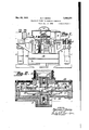
- Fig. l is a side elevation, partly in section, of my improved magnetic compass with a follow-up device for remote control.
- Fig. 2 is a vertical section on a larger scale of the compass portion of the instrument located in the base of the device shown in Fig. 1.
- Fig. '3 is a plan view of the instrument shown in Fig. l on a smaller scale.
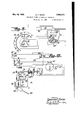
- Fig. 4 is a detail of one of the air actuated shutters or levers for governing the power driven follow-up and remote control devices, the contact being shown in the closed position.
- Fig. 5 is a plan view of the magnetic compass shown in Fig. 2 with the cover removed.
- Fig. 6 is a diagrammatic view showing the position assumed by the shutters when the air jet is displaced.
- Fig. 7 is a section taken approximately on line 1-4 of Fig. 5.
- Fig. 8 is a detail of the top of the instrument.
- Fig. 9 4 is a schematic view and wiring diagram showing how my invention may be employed to actuate the remote repeater compass.
- Fig. 10 is a wiring diagram of 'my invention also showing how it may be employed to automatically steer an aircraft in conjunction with a directional gyroscope.
- Fig. 11 is a detail showing a plan view of the disc containing the control jet in the magnetic. element.
- Figs. 1, 2 and 3 my compass is shown as supported in a shock proof manner on a pair of cushioned supports I and 2 on which are pivoted upright pins main frame 4 by means of a rubber mounting 5. Said support is shown as provided with a central follow-up contact at the 3 which support the' PATENT orrlca 12, assignor to Inc., Brooklyn,
- Said member is shown as exteriorly provided with slip rings I by means of which current is led" into the magnetic compass and also with apertures HI adjacent its top which communicate with a channel ll within sleeve 1, which in turn communicates with passageway l2 leading to pipe or hose coupling I3 by means of which air may be continuously withdrawn from the interior of the compass casing.
- Member 9 is shown as rotated by means of a worm gear I! secured to the top thereof and which is turned from the worm i5 driven in any suitable 15 manner by the follow-up motor l6 (Figs. 9 and 10).
- the drive from the motor is effected through universally coupled shafts l1 and IS, the latter driving bevel gear l9 which in turn drives bevel gear 20 on a shaft 2
- the entirecasing 22 for the magnetic compass element is supported by a member 9 so as to rotate therewith, the casing being shown as provided with apertures 23 and 24 at the top 25 so that air may be withdrawn from the interior of the case through the hollow sleeve 9.
- the magnetic element proper is shown as comprising one or more bar magnets 25 supported in a frame 26, which in turn is journalled in upper and lower jeweled bearings 21 and 28 within the casing.
- Said element is also preferably provided with a disc 30 whichnormally closely overlies but does not touch the lower inner portion or hub of a central partition 3
- a disc 30 whichnormally closely overlies but does not touch the lower inner portion or hub of a central partition 3
- Said disc is also provided with a hub-like ex-- 55 tension 33 from which rises the stem 34 carrying bearing pin 28.
- Both the hub and disc are provided with an eccentric bore or orifice 35 so as to permit a jet of air to be discharged upwardly therefrom.
- Above said jet are a pair of light, pivoted air paddles or vanes 36 and 3'! each provided with a semi-annular or forked end to encircle the central stem 34.
- One or both ends of both forks are provided with closely spaced knife edges 38 and 39 and 38' and '39.
- the vanes or paddles 36 and 31 are pivoted at 40 and 4
- Each of the aforesaid paddles is normally yieldingly pressed downwardly by light leaf spring 45 pivoted at 46 and bearing at one end against the under surface of one of the rivets 41 attaching T- shaped contact 42 to the vane. Said spring at the other end bears against an adjustable set screw 48 by means of which the force tending to hold the outer end of the paddle or shutter down may be accurately adjusted.
- the air jet strikes both shutters equally, holding both upwardly as shown in Fig. 2, a portion of the air escaping between the knife edges of the shutters 36, 31.
- the air jet will no longer engage the end of the paddle 36 with sufficient force to hold the same elevated against the action of the leaf spring.
- the shutter will, therefore, fall to the full line position in Fig. 6 and thus break the circuit between contacts 43 and 44.
- the upper adjacent edges of the two paddles are beveled or sharpened so that the air passing between the paddles, as shown in Fig. 6, exerts a downward force on the lower lever, thus increasing the sensitiveness of the control.
- the motor I6 is provided with opposite field windings 50, 50' which are normally equally'excited when the contacts are closed on both sides, the motor standing still under those circumstances.
- the circuit through the field 50' will be broken, thus leaving only the field 50 in control so that the motor is driven in the proper direction to cause the member. 9 and the supporting casing 22 to turn until equilibrium is again restored. Obviously the reverse action takes place when only the shutter 31 is lowered.
- FIG. 9 shows diagrammatically how a repeater compass 52 may be driven from the magnetic compass by means of any suitable repeater system.
- a resistance coil 53 is mounted on a fixed part around the compass, over which travel three equi-distant brushes 54, 54' and 54" secured to the member 9.
- Themtential from said brushes is picked oil through the slip rings in and brushes 55 contacting therewith and carried to three field windings 56 on repeater motor 51, said motor having a polarized armature 58 to which the compass pointer 59 may be secured.
- My invention may also be employed for controlling the rudder of a craftfor automatic steering.
- One method of accomplishing this purpose is illustrated diagrammatically in Fig. 10.
- a contact arm 56 secured to member 9 by a spring pressed slip friction connection 51' (see Figs. 1, 3 and 8) so that said member will revolve with member 9 until it strikes fixed stops in either direction.
- Such stops are shown as a pair of contacts 60 and 60' secured to a fixed part 6
- Said contacts are shown in circuit with a reversible motor 62 which may control the rudder directly or indirectly.
- the rudder is controlled jointly by the magnetic compass and a directional gyroscope 63 as generally indicated in the prior application of Elmer A.
- the gyroscope controls the rudder 64 through contacts 65, 65' (or other suitable means) on the rotatably mounted base 69 of the gyroscope and a cooperating contact 66 secured to the vertical ring of the gyroscope.
- said contacts control solenoid operated clutches 61, 61' for turning the rudder from wind driven servo motor 68 in either direction.
- the magnetic compass control is shown as turning the base 69 through a Worm 10.
- Preferably high reduction gearing H is placed between the motor shaft and the worm so that the main control is effected from the gyroscope subject to correction by the average position oi the magnetic compass.
- a diiferen'tial H by means of which a follow-back connection 12 is introduced from the servo motor.
- a setting knob 13 by means of which the course may be changed at will.
- servo motor control may be employed, if desired.
- a remote or power control for magnetic compasses and the like comprising the combination with the magnetic needle element, a disc thereon, means for maintaining a superior air pressure thereunder than above the same to support the weight of said element, said element also having an eccentric aperture through which some of said air pressure escapes, a pair oi biased pivoted vanes, the ends or which lie adjacent said aperture, and power means controlled by the relative movement of said vanes.
- a remote or power control for magnetic compasses and the like comprising the combination with the magnetic needle element, a disc thereon, means for maintaining a superior air pressure thereunder than above the same to support the weight of said element, said disc also having an aperture eccentrically positioned therein through which some 01' said air pressure escapes,'a pair of biased pivoted vanes, the ends of which lie adjacent said aperture, and power means controlled by the difierential movement of said vanes as the eccentric aperture moves under one more than the othe 3.
- a remote or power control for magnetic compasses and the like comprising the combina- I element also having 'air pressure escapes, a
- a follow-up system for sensitive rotatable elements the combination with a housing for the same, means for maintaining a diflerential air without the housing, discs on said element for substantially closing said housing but permitting a flow of air between the same and the housing to float the element on air bearings, an aperture in said element leading from within to without said housing, a pair of paddles pivoted to each side of said aperture and having the inner edges lying normally equally in the path of the air stream'irom said aperture,
- a remote or power control for magnetic compasses and the like comprising the combination with the pivoted magnetic needle element, a disc thereon, means for maintaining a superior air pressure undersaid disc than above it to support the weight of said element, said element also having an aperture eccentric to the pivot axis of said element through which some of said air pressure escapes, and a second disc on said element adapted to exert a down pressure thereon to oflset a too great lifting power by said first disc.
Landscapes
- Engineering & Computer Science (AREA)
- Radar, Positioning & Navigation (AREA)
- Remote Sensing (AREA)
- Physics & Mathematics (AREA)
- General Physics & Mathematics (AREA)
- Toys (AREA)
Description
May 28, 1935. F, BATE 2,003,270
FOLLOW-UP SYSTEM FOR MAGNETIC COMPASSES Filed Jan. 11, 1934 3 Sheets-Sheet l 4 6 2.5 34- 46! "i r A 9 i n rUJIf- S O O o 0 4 5 x 1 36": l E5 P-A- -L I 32/ J0 .92 2 l 21 g 32 INVENTOR ,May 28, 1935. M. F; BATES 2,003,270
' FOLLOW-UP SYSTEM FOR MAGNETIC COMPASSES Filed Jan. 11, 1934 s Sheets-Sheet 2 as 4@ e7 47 7% l I I INVENTOR Nam/Mam? A758 May 28, 1935.
M. F. BATES Filed Jan. 11, 1934 3 Sheets-Sheet 3 Hllll IIIW g 7 6 s m INVENTORY IZonnms R/T' HTES MM ZL M HIS ATTORNEY Patented May 28, 1935 FOLLOW-UP SYSTEM FOR MAGNETIC COMPASSES Mortimer F. Bates, Brooklyn, N.
Sperry Gyroscope Company, N. Y., a corporation of New York Application January 11, 1934, Serial No.
' 6 Claims.
This invention relates to magnetic compasses and more especially to a means for controlling another device from a magnetic compass without disturbing the latter. For instance, it is often 5 desirable to locate the magnetic, compass remote from magnetic influences in an airplane or ship and to actuate therefrom an indicator at a distance, or it may be desirable to effect the automatic steering of aircraft or ship from a magnetic compass by means of a power actuated remote control device either in conjunction with or without a gyroscopic directional device. My invention further relates to a means for improving the accuracy of magnetic compasses by relieving the pivots of the load due to the weight of the mag netic element.
Referring to the drawings illustrating the preferred form my invention may assume,
Fig. l is a side elevation, partly in section, of my improved magnetic compass with a follow-up device for remote control.
Fig. 2 is a vertical section on a larger scale of the compass portion of the instrument located in the base of the device shown in Fig. 1.
Fig. '3 is a plan view of the instrument shown in Fig. l on a smaller scale.
Fig. 4 is a detail of one of the air actuated shutters or levers for governing the power driven follow-up and remote control devices, the contact being shown in the closed position.
Fig. 5 is a plan view of the magnetic compass shown in Fig. 2 with the cover removed.
Fig. 6 is a diagrammatic view showing the position assumed by the shutters when the air jet is displaced.
Fig. 7 is a section taken approximately on line 1-4 of Fig. 5.
Fig. 8 is a detail of the top of the instrument. Fig. 9 4 is a schematic view and wiring diagram showing how my invention may be employed to actuate the remote repeater compass.
Fig. 10 is a wiring diagram of 'my invention also showing how it may be employed to automatically steer an aircraft in conjunction with a directional gyroscope.
Fig. 11 is a detail showing a plan view of the disc containing the control jet in the magnetic. element.
Referring first to Figs. 1, 2 and 3, my compass is shown as supported in a shock proof manner on a pair of cushioned supports I and 2 on which are pivoted upright pins main frame 4 by means of a rubber mounting 5. Said support is shown as provided with a central follow-up contact at the 3 which support the' PATENT orrlca 12, assignor to Inc., Brooklyn,
As shown in Fig. 3, the drive from the motor is effected through universally coupled shafts l1 and IS, the latter driving bevel gear l9 which in turn drives bevel gear 20 on a shaft 2| of the worm IS. The entirecasing 22 for the magnetic compass element is suported by a member 9 so as to rotate therewith, the casing being shown as provided with apertures 23 and 24 at the top 25 so that air may be withdrawn from the interior of the case through the hollow sleeve 9. The magnetic element proper is shown as comprising one or more bar magnets 25 supported in a frame 26, which in turn is journalled in upper and lower jeweled bearings 21 and 28 within the casing. Said element is also preferably provided with a disc 30 whichnormally closely overlies but does not touch the lower inner portion or hub of a central partition 3| within the casing. It will readily be seen that as air is withdrawn through member 9 and admitted through apertures 32 inthe base of the instrument, that a superior pres.- sure will exist underneath the disc so as to lift or tend to lift the magnetic element, thereby relieving the bearings 21 and 28 of any gravitational load. The pressure underneath the disc 30, however, may be greater than necessary to overcome the weight of the magnetic element because its effective diameter is determined by the necessary off center position of orifice 35, hereinafter described. Therefore, it may be necessary to offset this pressure by a second and smaller disc 30' acting in the direction of gravity, the diflerence in effective areas of 30 and 30 being exactly calculated to equal the weight of the magnetic element when the operating vacuum is normal;
Said disc is also provided with a hub-like ex-- 55 tension 33 from which rises the stem 34 carrying bearing pin 28. Both the hub and disc are provided with an eccentric bore or orifice 35 so as to permit a jet of air to be discharged upwardly therefrom. Above said jet are a pair of light, pivoted air paddles or vanes 36 and 3'! each provided with a semi-annular or forked end to encircle the central stem 34. One or both ends of both forks are provided with closely spaced knife edges 38 and 39 and 38' and '39. The vanes or paddles 36 and 31 are pivoted at 40 and 4| respectively, and are shown as having riveted to their rear ends T-shaped contact pieces 42, 42' which, when one vane is lowered, bridges stationary contacts 43 and 44 to complete a circuit directly or indirectly to drive the follow-up motor IS in one direction, While the other vane drives the motor in the other direction. Each of the aforesaid paddles is normally yieldingly pressed downwardly by light leaf spring 45 pivoted at 46 and bearing at one end against the under surface of one of the rivets 41 attaching T- shaped contact 42 to the vane. Said spring at the other end bears against an adjustable set screw 48 by means of which the force tending to hold the outer end of the paddle or shutter down may be accurately adjusted. Normally the air jet strikes both shutters equally, holding both upwardly as shown in Fig. 2, a portion of the air escaping between the knife edges of the shutters 36, 31. In case, however, of relative turning" of the magnetic element and follow-up support (for example, so that the magnetic element moves to the left in Fig. 6) the air jet will no longer engage the end of the paddle 36 with sufficient force to hold the same elevated against the action of the leaf spring. The shutter will, therefore, fall to the full line position in Fig. 6 and thus break the circuit between contacts 43 and 44. Preferably the upper adjacent edges of the two paddles are beveled or sharpened so that the air passing between the paddles, as shown in Fig. 6, exerts a downward force on the lower lever, thus increasing the sensitiveness of the control.
As shown, the motor I6 is provided with opposite field windings 50, 50' which are normally equally'excited when the contacts are closed on both sides, the motor standing still under those circumstances. When, however, due to the lowering of one paddle, 36 for example, contacts 43, 44 are broken, the circuit through the field 50' will be broken, thus leaving only the field 50 in control so that the motor is driven in the proper direction to cause the member. 9 and the supporting casing 22 to turn until equilibrium is again restored. Obviously the reverse action takes place when only the shutter 31 is lowered.
Since the follow-up support is power driven, obviously repeater devices may be controlled therefrom without eifecting the magnetic compass. Thus Fig. 9 shows diagrammatically how a repeater compass 52 may be driven from the magnetic compass by means of any suitable repeater system. As shown, a resistance coil 53 is mounted on a fixed part around the compass, over which travel three equi- distant brushes 54, 54' and 54" secured to the member 9. Themtential from said brushes is picked oil through the slip rings in and brushes 55 contacting therewith and carried to three field windings 56 on repeater motor 51, said motor having a polarized armature 58 to which the compass pointer 59 may be secured.
My invention may also be employed for controlling the rudder of a craftfor automatic steering. One method of accomplishing this purpose is illustrated diagrammatically in Fig. 10. On top of member 9 is mounted a contact arm 56 secured to member 9 by a spring pressed slip friction connection 51' (see Figs. 1, 3 and 8) so that said member will revolve with member 9 until it strikes fixed stops in either direction. Such stops are shown as a pair of contacts 60 and 60' secured to a fixed part 6| on the compass framework. Said contacts are shown in circuit with a reversible motor 62 which may control the rudder directly or indirectly. Preferably the rudder is controlled jointly by the magnetic compass and a directional gyroscope 63 as generally indicated in the prior application of Elmer A. Sperry, Jr., now Patent No. 1,982,702, dated December 4, 1934, for Gyro pilots for aircraft. According to this system, the gyroscope controls the rudder 64 through contacts 65, 65' (or other suitable means) on the rotatably mounted base 69 of the gyroscope and a cooperating contact 66 secured to the vertical ring of the gyroscope. As shown, said contacts control solenoid operated clutches 61, 61' for turning the rudder from wind driven servo motor 68 in either direction. The magnetic compass control is shown as turning the base 69 through a Worm 10. Preferably high reduction gearing H is placed between the motor shaft and the worm so that the main control is effected from the gyroscope subject to correction by the average position oi the magnetic compass. There is also shown interposed a diiferen'tial H by means of which a follow-back connection 12 is introduced from the servo motor. There is also shown a setting knob 13 by means of which the course may be changed at will. Obviously other types of servo motor control may be employed, if desired.
In accordance with the provisions of the patent statutes, I have herein described the principle and operation of my invention, together with the apparatus which I now consider to represent the best embodiment thereof, but I desire to have it understood that the apparatus shown is only illustrative and that the invention can be carried out by other means. Also, while it is designed to use the various features and elements in the combination and relations described, some of these may be altered and others omitted without interfering with the more general results outlined, and the invention extends to such use.
Having described my invention, what I claim and desire to secure by Letters Patent 18:
1. A remote or power control for magnetic compasses and the like comprising the combination with the magnetic needle element, a disc thereon, means for maintaining a superior air pressure thereunder than above the same to support the weight of said element, said element also having an eccentric aperture through which some of said air pressure escapes, a pair oi biased pivoted vanes, the ends or which lie adjacent said aperture, and power means controlled by the relative movement of said vanes.
2. A remote or power control for magnetic compasses and the like comprising the combination with the magnetic needle element, a disc thereon, means for maintaining a superior air pressure thereunder than above the same to support the weight of said element, said disc also having an aperture eccentrically positioned therein through which some 01' said air pressure escapes,'a pair of biased pivoted vanes, the ends of which lie adjacent said aperture, and power means controlled by the difierential movement of said vanes as the eccentric aperture moves under one more than the othe 3. A remote or power control for magnetic compasses and the like comprising the combina- I element also having 'air pressure escapes, a
pivoted to each side tion with the rotatable element supporting the needle, means for maintaining a superior air pressure thereunder than above the same, said an aperture eccentrically positioned therein through which some of said pair of biased pivoted vanes, the ends of which lie adjacent said aperture, and power means controlled by the diflerential movement of said vanes as the eccentric aperture moves under one-more than the other.
4. In a follow-up system-for sensitive rotatable elements, the combination with a housing for the same, means for maintaining a diflerential air pressure within and without the housing, discs on said element for substantially closing said housing but permitting a flow of air between the same and the housing to float the element on air bearings, an aperture in said element leading from within to without said housing, a pair oi! paddles of said aperture and having the inner edges lying normally equally in the path or the air stream from said aperture, means,
normally partially biasing each paddle against said air stream, power means brought into action by the differential movement of the paddles for turning said housing to follow said element.
pressure within and dies for turning said 5. In a follow-up system for sensitive rotatable elements, the combination with a housing for the same, means for maintaining a diflerential air without the housing, discs on said element for substantially closing said housing but permitting a flow of air between the same and the housing to float the element on air bearings, an aperture in said element leading from within to without said housing, a pair of paddles pivoted to each side of said aperture and having the inner edges lying normally equally in the path of the air stream'irom said aperture,
means normally partially biasing each paddle against said air stream, power means brought into action by the diflerential movement of the padhousingto follow said element, and a transmitter actuated thereby for transmitting the readings to a distance.
6. A remote or power control for magnetic compasses and the like comprising the combination with the pivoted magnetic needle element, a disc thereon, means for maintaining a superior air pressure undersaid disc than above it to support the weight of said element, said element also having an aperture eccentric to the pivot axis of said element through which some of said air pressure escapes, and a second disc on said element adapted to exert a down pressure thereon to oflset a too great lifting power by said first disc.
MOR'I'IMER F. BATES.
Priority Applications (1)
| Application Number | Priority Date | Filing Date | Title |
|---|---|---|---|
| US706207A US2003270A (en) | 1934-01-11 | 1934-01-11 | Follow-up system for magnetic compasses |
Applications Claiming Priority (1)
| Application Number | Priority Date | Filing Date | Title |
|---|---|---|---|
| US706207A US2003270A (en) | 1934-01-11 | 1934-01-11 | Follow-up system for magnetic compasses |
Publications (1)
| Publication Number | Publication Date |
|---|---|
| US2003270A true US2003270A (en) | 1935-05-28 |
Family
ID=24836638
Family Applications (1)
| Application Number | Title | Priority Date | Filing Date |
|---|---|---|---|
| US706207A Expired - Lifetime US2003270A (en) | 1934-01-11 | 1934-01-11 | Follow-up system for magnetic compasses |
Country Status (1)
| Country | Link |
|---|---|
| US (1) | US2003270A (en) |
-
1934
- 1934-01-11 US US706207A patent/US2003270A/en not_active Expired - Lifetime
Similar Documents
| Publication | Publication Date | Title |
|---|---|---|
| US2190390A (en) | Automatic steering device for aircraft | |
| US1992970A (en) | Hydropneumatic automatic pilot | |
| US1988521A (en) | Gyro earth inductor compass | |
| US2280116A (en) | Automatic means for caging gyroscopes | |
| US2126855A (en) | Direction maintaining means for use on dirigible craft | |
| US2003270A (en) | Follow-up system for magnetic compasses | |
| US2093503A (en) | Artificial horizon | |
| US1924037A (en) | Gyroscopic navigational instrument | |
| US1923290A (en) | Airplane control | |
| GB345127A (en) | Improvements in or relating to gyroscopes | |
| US2091306A (en) | Level flight control for automatic pilots | |
| US2406879A (en) | Damping eliminator for gyroscopic compasses | |
| US2058306A (en) | Robot navigator | |
| US2280797A (en) | Aerial flight instrument | |
| US2360399A (en) | Directional gyroscope and follow-up | |
| US2219964A (en) | and more particularly directional gyro for | |
| US1805854A (en) | Nonpendulous gyrocompass | |
| US2116103A (en) | Compass for automatic pilots | |
| US1368226A (en) | Aeroplane-stabilizer | |
| US2177242A (en) | Aircraft automatic pilot | |
| US2157360A (en) | Correction device for gyrocompasses | |
| US2513329A (en) | Gyro vertical | |
| GB397654A (en) | Improvements in or relating to gyroscopic compasses | |
| US1779991A (en) | Automatic pilot | |
| US1573109A (en) | Stability and steering device for aircraft |