US20030198846A1 - Integrated fuel cell power system - Google Patents
Integrated fuel cell power system Download PDFInfo
- Publication number
- US20030198846A1 US20030198846A1 US10/126,165 US12616502A US2003198846A1 US 20030198846 A1 US20030198846 A1 US 20030198846A1 US 12616502 A US12616502 A US 12616502A US 2003198846 A1 US2003198846 A1 US 2003198846A1
- Authority
- US
- United States
- Prior art keywords
- fuel
- fuel cell
- power system
- cell power
- supply unit
- Prior art date
- Legal status (The legal status is an assumption and is not a legal conclusion. Google has not performed a legal analysis and makes no representation as to the accuracy of the status listed.)
- Granted
Links
Images


Classifications
-
- H—ELECTRICITY
- H01—ELECTRIC ELEMENTS
- H01M—PROCESSES OR MEANS, e.g. BATTERIES, FOR THE DIRECT CONVERSION OF CHEMICAL ENERGY INTO ELECTRICAL ENERGY
- H01M8/00—Fuel cells; Manufacture thereof
- H01M8/04—Auxiliary arrangements, e.g. for control of pressure or for circulation of fluids
- H01M8/04082—Arrangements for control of reactant parameters, e.g. pressure or concentration
- H01M8/04089—Arrangements for control of reactant parameters, e.g. pressure or concentration of gaseous reactants
-
- H—ELECTRICITY
- H01—ELECTRIC ELEMENTS
- H01M—PROCESSES OR MEANS, e.g. BATTERIES, FOR THE DIRECT CONVERSION OF CHEMICAL ENERGY INTO ELECTRICAL ENERGY
- H01M8/00—Fuel cells; Manufacture thereof
- H01M8/04—Auxiliary arrangements, e.g. for control of pressure or for circulation of fluids
- H01M8/04082—Arrangements for control of reactant parameters, e.g. pressure or concentration
- H01M8/04201—Reactant storage and supply, e.g. means for feeding, pipes
- H01M8/04208—Cartridges, cryogenic media or cryogenic reservoirs
-
- H—ELECTRICITY
- H01—ELECTRIC ELEMENTS
- H01M—PROCESSES OR MEANS, e.g. BATTERIES, FOR THE DIRECT CONVERSION OF CHEMICAL ENERGY INTO ELECTRICAL ENERGY
- H01M8/00—Fuel cells; Manufacture thereof
- H01M8/24—Grouping of fuel cells, e.g. stacking of fuel cells
- H01M8/2465—Details of groupings of fuel cells
- H01M8/247—Arrangements for tightening a stack, for accommodation of a stack in a tank or for assembling different tanks
- H01M8/2475—Enclosures, casings or containers of fuel cell stacks
-
- H—ELECTRICITY
- H01—ELECTRIC ELEMENTS
- H01M—PROCESSES OR MEANS, e.g. BATTERIES, FOR THE DIRECT CONVERSION OF CHEMICAL ENERGY INTO ELECTRICAL ENERGY
- H01M8/00—Fuel cells; Manufacture thereof
- H01M8/24—Grouping of fuel cells, e.g. stacking of fuel cells
- H01M8/2465—Details of groupings of fuel cells
- H01M8/2484—Details of groupings of fuel cells characterised by external manifolds
- H01M8/2485—Arrangements for sealing external manifolds; Arrangements for mounting external manifolds around a stack
-
- H—ELECTRICITY
- H01—ELECTRIC ELEMENTS
- H01M—PROCESSES OR MEANS, e.g. BATTERIES, FOR THE DIRECT CONVERSION OF CHEMICAL ENERGY INTO ELECTRICAL ENERGY
- H01M8/00—Fuel cells; Manufacture thereof
- H01M8/10—Fuel cells with solid electrolytes
- H01M2008/1095—Fuel cells with polymeric electrolytes
-
- Y—GENERAL TAGGING OF NEW TECHNOLOGICAL DEVELOPMENTS; GENERAL TAGGING OF CROSS-SECTIONAL TECHNOLOGIES SPANNING OVER SEVERAL SECTIONS OF THE IPC; TECHNICAL SUBJECTS COVERED BY FORMER USPC CROSS-REFERENCE ART COLLECTIONS [XRACs] AND DIGESTS
- Y02—TECHNOLOGIES OR APPLICATIONS FOR MITIGATION OR ADAPTATION AGAINST CLIMATE CHANGE
- Y02E—REDUCTION OF GREENHOUSE GAS [GHG] EMISSIONS, RELATED TO ENERGY GENERATION, TRANSMISSION OR DISTRIBUTION
- Y02E60/00—Enabling technologies; Technologies with a potential or indirect contribution to GHG emissions mitigation
- Y02E60/30—Hydrogen technology
- Y02E60/50—Fuel cells
Definitions
- the present invention relates to fuel cell power systems.
- Fuel cell power systems include a number of components, including the fuel cell stack, the fuel supply, a pressure regulator to control the flow of the fuel supply, and various tubes and fittings which serve as manifolds for distribution of fuel through the system.
- Fuel cells typically use hydrogen gas as a fuel but other fuels such as methyl alcohol (methanol) or reformed hydrocarbons (reformate) may be used.
- Fuel cell power systems are typically manufactured by acquiring the various components as stand-alone products, and then assembling them into a fuel cell system.
- typical fuel cell systems are not created as integrated systems, but rather are pieced together from stand-alone components.
- the present invention is an integrated fuel cell system, comprised of a fuel cell stack or stacks, an integrated, multi-function mounting plate, fuel supply unit(s), a distribution manifold, a gas pressure regulator, and a cover.
- the present invention helps improve fuel cell operation, and lowers component count and assembly costs.
- FIG. 1 is a perspective view of a fuel cell system according to the present invention, without a cover.
- FIG. 2 is a perspective view of a fuel cell system according to the present invention, with a cover.
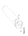
- FIG. 3 a is a perspective view of a fuel supply unit with a bayonet mount.
- FIG. 3 b is a perspective view of another fuel supply unit with a spring-loaded mount.
- FIG. 4 is a perspective view of a mounting plate according to the present invention, showing the internal gas distribution plumbing.
- the present invention is an integrated fuel cell power system 10 , comprised of a fuel cell stack 20 , an integrated, multi-function mounting plate 30 , fuel supply unit(s) 40 , 42 , a distribution manifold 50 , a gas pressure regulator 60 , and a cover 70 .
- the fuel cell stack 20 is comprised of an array of individual fuel cells 22 , and an end plate 24 .
- the mounting plate 30 functions as a fuel cell end plate.
- the integrated system of the present invention can work with virtually any polymer electrolyte membrane (PEM) fuel cell stack, including but not limited to stacks comprised of integrated fuel cells, or more conventional stacks comprised of fuel cells assembled from separate stand-alone components.
- PEM polymer electrolyte membrane
- the present invention can work with systems that use ambient or pressurized air as an oxidizer, either in natural convection mode or forced air mode.
- the mounting plate 30 serves two functions. First, the plate serves as an end plate for the fuel cell stack.
- a fuel distribution manifold 50 receives fuel from the fuel supply units 40 , 42 . From the manifold, the fuel passes through the regulator 60 and into the stack 20 .
- the distribution manifold contains valves 52 , 54 for receiving fuel from the fuel supply units 40 , 42 . These valves engage complementary valve 44 attached to the fuel supply unit(s). Both manifold valves 52 , 54 and the fuel supply unit valve 44 are self-sealing, so that when the fuel supply units are removed from the manifold the valves close, ensuring that no gas will escape.
- the manifold 50 distributes high pressure gas to the pressure regulator 60 , FIG. 1, through internal passages 56 , 58 and regulator inlet port 62 shown in FIG. 4.
- the pressure regulator 60 reduces the pressure of the fuel gas so that is suitable for use by the fuel cell stack.
- Regulators of a suitable type can be supplied commercially from different vendors, for example: Air-Logic, 5102 Douglass Avenue, Racine, Wis.
- the regulated fuel is then conveyed out of the pressure regulator to the fuel cell stack 20 by passing from the pressure regulator through the regulated gas pressure port 64 of the distribution manifold 50 and then through internal passage 57 and into the fuel cell stack by way of the fuel cell inlet port 66 .
- the regulated gas can also be transmitted to the stack 20 from the regulator 60 through external piping hoses or tubes.
- the output pressure of the regulator is adjusted or set by means of a set screw, knob, dial, or other output control means.
- the pressure regulator can but need not be integrated with the mounting plate.
- the mounting plate can be expanded to accommodate more than one set of manifolds and pressure regulators, so that more than one set of fuel cell stacks can be used with a single plate.
- the fuel supply units can take many forms. As shown in FIG. 1, 3 a , and 3 b , they can be in the form of conventional pressurized gas storage bottles or methanol tanks. Additionally, metal hydride fuel cartridges can be used, such as the “Hydrogen Storage System, Model Number ST-1-AL” supplied by ERGENICS, INC., 247 Margaret King Ave., Ringwood, N.J. Fuel can also be supplied from an external source such as large pressurized hydrogen gas bottles or other standard methods of supplying hydrogen such as reformers. The units can connect to the distribution manifold through a bayonet-type connection 46 , as shown in FIG. 3, or through other conventional methods known to those skilled in the mechanical arts, including but not limited to a screw thread, or spring-loaded attachments 48 . (FIG. 3 b ).
- the system of the present invention can be operated continuously, meaning that replacement fuel sources can be removed and reinstalled while the system is operating, resulting in uninterrupted use.
- both fuel supply units are removable fuel units, and a single spent fuel unit can be removed and replaced while the system operates off the other one.
- one fuel supply unit or cartridge is permanent and the other is removable.
- the system can run off the permanent supply while the removable supply is replaced with a fresh cartridge or other supply unit.
- the permanent supply can then be refilled from fuel in the removable unit.
- the permanent supply can take the form of a pressurized gas bottle, a hydride cartridge, bladder, or other suitable container. Even those with little or no technical experience should have little trouble replacing cartridges or other supply units within the present invention.
- the fuel supply units are recharged or refilled using standard methods used in the industry.
- the valve 44 opens automatically when connected to a charging or filling unit and when charged or refilled and removed from the charging or filling unit they then self seal and are ready for immediate use.
- the cover 70 encloses the fuel cell system, but allows for easy access to the fuel supply units 40 , 42 .
- the fuel supply units 40 , 42 can be removed without removing the cover 70 .
- the cover has slots 72 or louvers to facilitate proper air circulation.
Landscapes
- Life Sciences & Earth Sciences (AREA)
- Engineering & Computer Science (AREA)
- Manufacturing & Machinery (AREA)
- Sustainable Development (AREA)
- Sustainable Energy (AREA)
- Chemical & Material Sciences (AREA)
- Chemical Kinetics & Catalysis (AREA)
- Electrochemistry (AREA)
- General Chemical & Material Sciences (AREA)
- Fuel Cell (AREA)
Abstract
Description
- The present invention relates to fuel cell power systems.
- Fuel cell power systems include a number of components, including the fuel cell stack, the fuel supply, a pressure regulator to control the flow of the fuel supply, and various tubes and fittings which serve as manifolds for distribution of fuel through the system. Fuel cells typically use hydrogen gas as a fuel but other fuels such as methyl alcohol (methanol) or reformed hydrocarbons (reformate) may be used.
- Fuel cell power systems are typically manufactured by acquiring the various components as stand-alone products, and then assembling them into a fuel cell system. In other words, typical fuel cell systems are not created as integrated systems, but rather are pieced together from stand-alone components.
- As a result of this piecemeal assembly, previous fuel cell systems have required an inordinate number of parts, particularly for the various components that distribute gases throughout the system. With so many components, the cost of assembling fuel cell systems has been unnecessarily high. By integrating the system, the component count could be lowered, and the assembly cost reduced.
- The present invention is an integrated fuel cell system, comprised of a fuel cell stack or stacks, an integrated, multi-function mounting plate, fuel supply unit(s), a distribution manifold, a gas pressure regulator, and a cover. By integrating components, the present invention helps improve fuel cell operation, and lowers component count and assembly costs.
- FIG. 1 is a perspective view of a fuel cell system according to the present invention, without a cover.
- FIG. 2 is a perspective view of a fuel cell system according to the present invention, with a cover.
- FIG. 3 a is a perspective view of a fuel supply unit with a bayonet mount.
- FIG. 3 b is a perspective view of another fuel supply unit with a spring-loaded mount.
- FIG. 4 is a perspective view of a mounting plate according to the present invention, showing the internal gas distribution plumbing.
- The present invention is an integrated fuel
cell power system 10, comprised of afuel cell stack 20, an integrated,multi-function mounting plate 30, fuel supply unit(s) 40, 42, adistribution manifold 50, agas pressure regulator 60, and acover 70. - As shown in FIG. 1, the
fuel cell stack 20 is comprised of an array of individual fuel cells 22, and anend plate 24. Themounting plate 30 functions as a fuel cell end plate. The integrated system of the present invention can work with virtually any polymer electrolyte membrane (PEM) fuel cell stack, including but not limited to stacks comprised of integrated fuel cells, or more conventional stacks comprised of fuel cells assembled from separate stand-alone components. The present invention can work with systems that use ambient or pressurized air as an oxidizer, either in natural convection mode or forced air mode. - As shown in FIGS. 1 & 4, the
mounting plate 30 serves two functions. First, the plate serves as an end plate for the fuel cell stack. - Second, integrated within or attached to the mounting plate is a
fuel distribution manifold 50, and agas pressure regulator 60. The manifold receives fuel from thefuel supply units regulator 60 and into thestack 20. The distribution manifold containsvalves 52, 54 for receiving fuel from thefuel supply units complementary valve 44 attached to the fuel supply unit(s). Bothmanifold valves 52, 54 and the fuelsupply unit valve 44 are self-sealing, so that when the fuel supply units are removed from the manifold the valves close, ensuring that no gas will escape. - The
manifold 50 distributes high pressure gas to thepressure regulator 60, FIG. 1, throughinternal passages regulator inlet port 62 shown in FIG. 4. - The
pressure regulator 60 reduces the pressure of the fuel gas so that is suitable for use by the fuel cell stack. Regulators of a suitable type can be supplied commercially from different vendors, for example: Air-Logic, 5102 Douglass Avenue, Racine, Wis. The regulated fuel is then conveyed out of the pressure regulator to thefuel cell stack 20 by passing from the pressure regulator through the regulatedgas pressure port 64 of thedistribution manifold 50 and then throughinternal passage 57 and into the fuel cell stack by way of the fuelcell inlet port 66. The regulated gas can also be transmitted to thestack 20 from theregulator 60 through external piping hoses or tubes. The output pressure of the regulator is adjusted or set by means of a set screw, knob, dial, or other output control means. The pressure regulator can but need not be integrated with the mounting plate. - The mounting plate can be expanded to accommodate more than one set of manifolds and pressure regulators, so that more than one set of fuel cell stacks can be used with a single plate.
- The fuel supply units can take many forms. As shown in FIG. 1, 3 a, and 3 b, they can be in the form of conventional pressurized gas storage bottles or methanol tanks. Additionally, metal hydride fuel cartridges can be used, such as the “Hydrogen Storage System, Model Number ST-1-AL” supplied by ERGENICS, INC., 247 Margaret King Ave., Ringwood, N.J. Fuel can also be supplied from an external source such as large pressurized hydrogen gas bottles or other standard methods of supplying hydrogen such as reformers. The units can connect to the distribution manifold through a bayonet-
type connection 46, as shown in FIG. 3, or through other conventional methods known to those skilled in the mechanical arts, including but not limited to a screw thread, or spring-loadedattachments 48. (FIG. 3b). - The system of the present invention can be operated continuously, meaning that replacement fuel sources can be removed and reinstalled while the system is operating, resulting in uninterrupted use. In one embodiment of the present invention, both fuel supply units are removable fuel units, and a single spent fuel unit can be removed and replaced while the system operates off the other one. In an alternative embodiment, one fuel supply unit or cartridge is permanent and the other is removable. The system can run off the permanent supply while the removable supply is replaced with a fresh cartridge or other supply unit. The permanent supply can then be refilled from fuel in the removable unit. The permanent supply can take the form of a pressurized gas bottle, a hydride cartridge, bladder, or other suitable container. Even those with little or no technical experience should have little trouble replacing cartridges or other supply units within the present invention.
- The fuel supply units are recharged or refilled using standard methods used in the industry. The
valve 44 opens automatically when connected to a charging or filling unit and when charged or refilled and removed from the charging or filling unit they then self seal and are ready for immediate use. - As shown in FIG. 2, the
cover 70 encloses the fuel cell system, but allows for easy access to thefuel supply units fuel supply units cover 70. The cover hasslots 72 or louvers to facilitate proper air circulation. - One skilled in the art will appreciate that the present invention can be practiced by other than the described embodiments, which are presented for purposes of illustration and not limitation. Various modifications and changes can be made to the fuel supply units, valves, pressure regulators, mounting plate and the like without departing to the scope of the present invention.
Claims (21)
Priority Applications (6)
| Application Number | Priority Date | Filing Date | Title |
|---|---|---|---|
| US10/126,165 US6824911B2 (en) | 2002-04-18 | 2002-04-18 | Integrated fuel cell power system |
| PCT/US2003/011322 WO2003090303A1 (en) | 2002-04-18 | 2003-04-14 | Integrated fuel cell power system |
| EP03746974A EP1495506A4 (en) | 2002-04-18 | 2003-04-14 | Integrated fuel cell power system |
| AU2003226360A AU2003226360A1 (en) | 2002-04-18 | 2003-04-14 | Integrated fuel cell power system |
| US10/973,044 US7183016B2 (en) | 2002-04-18 | 2004-10-25 | Integrated fuel cell power system |
| US11/626,117 US20070190371A1 (en) | 2002-04-18 | 2007-01-23 | Integrated fuel cell power system |
Applications Claiming Priority (1)
| Application Number | Priority Date | Filing Date | Title |
|---|---|---|---|
| US10/126,165 US6824911B2 (en) | 2002-04-18 | 2002-04-18 | Integrated fuel cell power system |
Related Child Applications (1)
| Application Number | Title | Priority Date | Filing Date |
|---|---|---|---|
| US10/973,044 Continuation US7183016B2 (en) | 2002-04-18 | 2004-10-25 | Integrated fuel cell power system |
Publications (2)
| Publication Number | Publication Date |
|---|---|
| US20030198846A1 true US20030198846A1 (en) | 2003-10-23 |
| US6824911B2 US6824911B2 (en) | 2004-11-30 |
Family
ID=29214960
Family Applications (3)
| Application Number | Title | Priority Date | Filing Date |
|---|---|---|---|
| US10/126,165 Expired - Lifetime US6824911B2 (en) | 2002-04-18 | 2002-04-18 | Integrated fuel cell power system |
| US10/973,044 Expired - Lifetime US7183016B2 (en) | 2002-04-18 | 2004-10-25 | Integrated fuel cell power system |
| US11/626,117 Abandoned US20070190371A1 (en) | 2002-04-18 | 2007-01-23 | Integrated fuel cell power system |
Family Applications After (2)
| Application Number | Title | Priority Date | Filing Date |
|---|---|---|---|
| US10/973,044 Expired - Lifetime US7183016B2 (en) | 2002-04-18 | 2004-10-25 | Integrated fuel cell power system |
| US11/626,117 Abandoned US20070190371A1 (en) | 2002-04-18 | 2007-01-23 | Integrated fuel cell power system |
Country Status (4)
| Country | Link |
|---|---|
| US (3) | US6824911B2 (en) |
| EP (1) | EP1495506A4 (en) |
| AU (1) | AU2003226360A1 (en) |
| WO (1) | WO2003090303A1 (en) |
Cited By (16)
| Publication number | Priority date | Publication date | Assignee | Title |
|---|---|---|---|---|
| US20040224209A1 (en) * | 2003-03-04 | 2004-11-11 | Kabushiki Kaisha Toshiba | Fuel cell unit for electronic apparatus |
| WO2005018037A1 (en) * | 2003-08-15 | 2005-02-24 | Hydrogenics Corporation | End plate for an electrochemical cell stack |
| US20060051638A1 (en) * | 2004-09-03 | 2006-03-09 | Gross Karl J | Hydrogen storage and integrated fuel cell assembly |
| US20060057040A1 (en) * | 2004-09-15 | 2006-03-16 | H Bank Technology Inc. | Portable hydrogen supply system |
| US20070037038A1 (en) * | 2005-08-15 | 2007-02-15 | Alfano Bryan L | Fuel supply manifold assembly |
| US20070264543A1 (en) * | 2006-05-15 | 2007-11-15 | Samsung Sdi Co., Ltd. | Fuel cell system |
| US20080145739A1 (en) * | 2003-07-29 | 2008-06-19 | Societe Bic | Fuel Supply Systems Having Operational Resistance |
| US20090220833A1 (en) * | 2005-09-21 | 2009-09-03 | Jones Eric T | Fuel Cell Device |
| US20090233150A1 (en) * | 2005-03-30 | 2009-09-17 | Kabushiki Kaisha Toshiba | Liquid injection device of fuel cell, fuel cell and fuel cartridge |
| EP1699700A4 (en) * | 2003-12-01 | 2009-10-28 | Bic Soc | Method and apparatus for filling a fuel container |
| EP2447162A1 (en) * | 2005-02-16 | 2012-05-02 | Société BIC | Fuel supply systems having operational resistance |
| WO2012131325A1 (en) * | 2011-03-30 | 2012-10-04 | Afc Energy Plc | Cell stack system |
| EP2457762A4 (en) * | 2009-07-21 | 2013-09-18 | Toyota Motor Co Ltd | FUEL SYSTEM AND VEHICLE |
| JP2015002123A (en) * | 2013-06-17 | 2015-01-05 | トヨタ自動車株式会社 | Fuel cell system |
| EP1848053B2 (en) † | 2005-02-09 | 2015-09-23 | Toyota Jidosha Kabushiki Kaisha | Fuel cell system |
| CN106910913A (en) * | 2015-12-18 | 2017-06-30 | 中国科学院大连化学物理研究所 | A kind of fuel cartridge for fuel cells |
Families Citing this family (5)
| Publication number | Priority date | Publication date | Assignee | Title |
|---|---|---|---|---|
| US6824911B2 (en) * | 2002-04-18 | 2004-11-30 | Altergy Systems | Integrated fuel cell power system |
| US7208246B2 (en) * | 2002-07-23 | 2007-04-24 | Hewlett-Packard Development Company, L.P. | Fuel cell with integrated heater and robust construction |
| US7537024B2 (en) * | 2003-07-29 | 2009-05-26 | Societe Bic | Fuel cartridge with connecting valve |
| WO2015085053A1 (en) * | 2013-12-04 | 2015-06-11 | 12 Th Man Technologies, Inc. | Gas cylinder interlock device and method of use |
| WO2025032151A1 (en) * | 2023-08-10 | 2025-02-13 | Robert Bosch Gmbh | Electrochemical device, electrochemical system, peripheral fluid module and electrochemical module |
Citations (6)
| Publication number | Priority date | Publication date | Assignee | Title |
|---|---|---|---|---|
| US6268077B1 (en) * | 1999-03-01 | 2001-07-31 | Motorola, Inc. | Portable fuel cell power supply |
| US6447945B1 (en) * | 2000-12-12 | 2002-09-10 | General Atomics | Portable electronic device powered by proton exchange membrane fuel cell |
| US6492055B1 (en) * | 1998-11-26 | 2002-12-10 | Kabushiki Kaisha Toshiba | Polymer electrolyte fuel stack |
| US6576361B1 (en) * | 2000-11-09 | 2003-06-10 | Ballard Power Systems Inc. | Method and apparatus for isolating a fuel cell assembly from its surroundings |
| US6627339B2 (en) * | 2000-04-19 | 2003-09-30 | Delphi Technologies, Inc. | Fuel cell stack integrated with a waste energy recovery system |
| US6773843B2 (en) * | 2001-03-09 | 2004-08-10 | Daido Metal Company Ltd. | Portable fuel cell stack |
Family Cites Families (9)
| Publication number | Priority date | Publication date | Assignee | Title |
|---|---|---|---|---|
| JP3135991B2 (en) * | 1992-06-18 | 2001-02-19 | 本田技研工業株式会社 | Fuel cell and fuel cell stack tightening method |
| JPH0737595A (en) * | 1993-07-21 | 1995-02-07 | Fuji Electric Co Ltd | Solid oxide fuel cell |
| JPH0992318A (en) * | 1995-09-22 | 1997-04-04 | Nippon Telegr & Teleph Corp <Ntt> | Portable fuel cell device |
| JP3509349B2 (en) * | 1995-12-20 | 2004-03-22 | 三洋電機株式会社 | Hybrid fuel cell |
| JPH1097862A (en) * | 1996-09-24 | 1998-04-14 | Matsushita Electric Ind Co Ltd | Power supply |
| US6159629A (en) * | 1998-12-17 | 2000-12-12 | Ballard Power Systems Inc. | Volume effecient layered manifold assembly for electrochemical fuel cell stacks |
| US6638650B1 (en) * | 2000-09-29 | 2003-10-28 | Ballard Power Systems Inc. | Method and apparatus for detecting transfer leaks in fuel cells and fuel cell stacks |
| US6861167B2 (en) * | 2001-07-25 | 2005-03-01 | Ballard Power Systems Inc. | Fuel cell resuscitation method and apparatus |
| US6824911B2 (en) * | 2002-04-18 | 2004-11-30 | Altergy Systems | Integrated fuel cell power system |
-
2002
- 2002-04-18 US US10/126,165 patent/US6824911B2/en not_active Expired - Lifetime
-
2003
- 2003-04-14 AU AU2003226360A patent/AU2003226360A1/en not_active Abandoned
- 2003-04-14 WO PCT/US2003/011322 patent/WO2003090303A1/en not_active Ceased
- 2003-04-14 EP EP03746974A patent/EP1495506A4/en not_active Withdrawn
-
2004
- 2004-10-25 US US10/973,044 patent/US7183016B2/en not_active Expired - Lifetime
-
2007
- 2007-01-23 US US11/626,117 patent/US20070190371A1/en not_active Abandoned
Patent Citations (6)
| Publication number | Priority date | Publication date | Assignee | Title |
|---|---|---|---|---|
| US6492055B1 (en) * | 1998-11-26 | 2002-12-10 | Kabushiki Kaisha Toshiba | Polymer electrolyte fuel stack |
| US6268077B1 (en) * | 1999-03-01 | 2001-07-31 | Motorola, Inc. | Portable fuel cell power supply |
| US6627339B2 (en) * | 2000-04-19 | 2003-09-30 | Delphi Technologies, Inc. | Fuel cell stack integrated with a waste energy recovery system |
| US6576361B1 (en) * | 2000-11-09 | 2003-06-10 | Ballard Power Systems Inc. | Method and apparatus for isolating a fuel cell assembly from its surroundings |
| US6447945B1 (en) * | 2000-12-12 | 2002-09-10 | General Atomics | Portable electronic device powered by proton exchange membrane fuel cell |
| US6773843B2 (en) * | 2001-03-09 | 2004-08-10 | Daido Metal Company Ltd. | Portable fuel cell stack |
Cited By (24)
| Publication number | Priority date | Publication date | Assignee | Title |
|---|---|---|---|---|
| US20040224209A1 (en) * | 2003-03-04 | 2004-11-11 | Kabushiki Kaisha Toshiba | Fuel cell unit for electronic apparatus |
| US8613297B2 (en) | 2003-07-29 | 2013-12-24 | Societe Bic | Fuel supply systems having operational resistance |
| US20080145739A1 (en) * | 2003-07-29 | 2008-06-19 | Societe Bic | Fuel Supply Systems Having Operational Resistance |
| WO2005018037A1 (en) * | 2003-08-15 | 2005-02-24 | Hydrogenics Corporation | End plate for an electrochemical cell stack |
| EP1699700A4 (en) * | 2003-12-01 | 2009-10-28 | Bic Soc | Method and apparatus for filling a fuel container |
| US7779873B2 (en) | 2003-12-01 | 2010-08-24 | Societe Bic | Method and apparatus for filling a fuel container |
| US20060051638A1 (en) * | 2004-09-03 | 2006-03-09 | Gross Karl J | Hydrogen storage and integrated fuel cell assembly |
| US7781109B2 (en) | 2004-09-03 | 2010-08-24 | Gross Karl J | Hydrogen storage and integrated fuel cell assembly |
| US20060057040A1 (en) * | 2004-09-15 | 2006-03-16 | H Bank Technology Inc. | Portable hydrogen supply system |
| EP1848053B2 (en) † | 2005-02-09 | 2015-09-23 | Toyota Jidosha Kabushiki Kaisha | Fuel cell system |
| EP2447162A1 (en) * | 2005-02-16 | 2012-05-02 | Société BIC | Fuel supply systems having operational resistance |
| US20090233150A1 (en) * | 2005-03-30 | 2009-09-17 | Kabushiki Kaisha Toshiba | Liquid injection device of fuel cell, fuel cell and fuel cartridge |
| EP1873857A4 (en) * | 2005-03-30 | 2010-01-20 | Toshiba Kk | Liquid filling device for fuel cell, fuel cell, and fuel cartridge |
| US20070037038A1 (en) * | 2005-08-15 | 2007-02-15 | Alfano Bryan L | Fuel supply manifold assembly |
| US7968244B2 (en) | 2005-08-15 | 2011-06-28 | Parker-Hannifin Corporation | Fuel supply manifold assembly |
| WO2007022155A3 (en) * | 2005-08-15 | 2007-05-24 | Parker Hannifin Corp | Fuel supply manifold assembly |
| US20090220833A1 (en) * | 2005-09-21 | 2009-09-03 | Jones Eric T | Fuel Cell Device |
| US20070264543A1 (en) * | 2006-05-15 | 2007-11-15 | Samsung Sdi Co., Ltd. | Fuel cell system |
| US8053130B2 (en) * | 2006-05-15 | 2011-11-08 | Samsung Sdi Co., Ltd. | Fuel cell system |
| EP2457762A4 (en) * | 2009-07-21 | 2013-09-18 | Toyota Motor Co Ltd | FUEL SYSTEM AND VEHICLE |
| US8844662B2 (en) | 2009-07-21 | 2014-09-30 | Toyota Jidosha Kabushiki Kaisha | Fuel system and vehicle |
| WO2012131325A1 (en) * | 2011-03-30 | 2012-10-04 | Afc Energy Plc | Cell stack system |
| JP2015002123A (en) * | 2013-06-17 | 2015-01-05 | トヨタ自動車株式会社 | Fuel cell system |
| CN106910913A (en) * | 2015-12-18 | 2017-06-30 | 中国科学院大连化学物理研究所 | A kind of fuel cartridge for fuel cells |
Also Published As
| Publication number | Publication date |
|---|---|
| AU2003226360A1 (en) | 2003-11-03 |
| EP1495506A1 (en) | 2005-01-12 |
| US6824911B2 (en) | 2004-11-30 |
| US20070190371A1 (en) | 2007-08-16 |
| US7183016B2 (en) | 2007-02-27 |
| US20050112438A1 (en) | 2005-05-26 |
| EP1495506A4 (en) | 2007-10-10 |
| WO2003090303A1 (en) | 2003-10-30 |
Similar Documents
| Publication | Publication Date | Title |
|---|---|---|
| US20070190371A1 (en) | Integrated fuel cell power system | |
| US8227121B2 (en) | Fuel cell supply including information storage device and control system | |
| US9728796B2 (en) | Fluidic distribution system and related methods | |
| CN101151752A (en) | Separable fuel cell power unit for vehicles | |
| EP2280441A3 (en) | Fuel cell system | |
| EP3550653A1 (en) | Integrated electrochemical compressor and cascade storage method and system | |
| US20070068599A1 (en) | Refueling station | |
| US20070072042A1 (en) | Portable fuel cell power source | |
| CN101258634A (en) | Fuel cell system for supplying drinking water and oxygen | |
| JP3933563B2 (en) | regulator | |
| US7029786B2 (en) | Single point watering apparatus for lead-acid battery | |
| KR20170042768A (en) | Multi-reformable fuel delivery systems and methods for fuel cells | |
| US7316859B2 (en) | Storage system and method for supplying hydrogen to a polymer membrane fuel cell | |
| CA2536330A1 (en) | Fuel cells with multidirectional fuel flow | |
| MXPA05010626A (en) | Transportable fuel cell generator. | |
| JP2005226715A (en) | Hydrogen feeder | |
| JP3631476B2 (en) | High-pressure hydrogen oxygen generator | |
| JPH10284100A (en) | Fuel cell | |
| JP3943006B2 (en) | Fuel supply device integrated structure | |
| CN223761001U (en) | Ink supply systems for biochemical printers and chip synthesis printing systems | |
| CN220086098U (en) | Integrated valve seat and fuel cell system | |
| CN220321051U (en) | Medical center oxygen supply system with modularized design | |
| JP4059431B2 (en) | Fuel cell system | |
| WO2001041240A3 (en) | Fuel cell system | |
| KR102797738B1 (en) | Overpressure prevention valve for regulator |
Legal Events
| Date | Code | Title | Description |
|---|---|---|---|
| AS | Assignment |
Owner name: ALTERGY SYSTEMS, CALIFORNIA Free format text: ASSIGNMENT OF ASSIGNORS INTEREST;ASSIGNOR:FRANKLIN, JERROLD E.;REEL/FRAME:014874/0102 Effective date: 20040715 |
|
| STCF | Information on status: patent grant |
Free format text: PATENTED CASE |
|
| FPAY | Fee payment |
Year of fee payment: 4 |
|
| FPAY | Fee payment |
Year of fee payment: 8 |
|
| FPAY | Fee payment |
Year of fee payment: 12 |
|
| AS | Assignment |
Owner name: ALTER DOMUS (US) LLC, AS AGENT, ILLINOIS Free format text: SECURITY INTEREST;ASSIGNORS:DETECTOR ELECTRONICS, LLC (F/K/A DETECTOR ELECTRONICS CORPORATION);FIREYE, LLC (F/K/A FIREYE INC.);DETECTOR ELECTRONICS BUYER US, LLC;AND OTHERS;REEL/FRAME:068102/0675 Effective date: 20240701 |