US20030198840A1 - Fuel cell system fluid recovery - Google Patents
Fuel cell system fluid recovery Download PDFInfo
- Publication number
- US20030198840A1 US20030198840A1 US10/429,535 US42953503A US2003198840A1 US 20030198840 A1 US20030198840 A1 US 20030198840A1 US 42953503 A US42953503 A US 42953503A US 2003198840 A1 US2003198840 A1 US 2003198840A1
- Authority
- US
- United States
- Prior art keywords
- fluid
- fluid collection
- gas
- fuel cell
- collection container
- Prior art date
- Legal status (The legal status is an assumption and is not a legal conclusion. Google has not performed a legal analysis and makes no representation as to the accuracy of the status listed.)
- Granted
Links
- 239000012530 fluid Substances 0.000 title claims abstract description 132
- 239000000446 fuel Substances 0.000 title claims abstract description 71
- 238000011084 recovery Methods 0.000 title description 10
- 238000000034 method Methods 0.000 claims abstract description 36
- 238000010926 purge Methods 0.000 claims abstract description 34
- XLYOFNOQVPJJNP-UHFFFAOYSA-N water Substances O XLYOFNOQVPJJNP-UHFFFAOYSA-N 0.000 claims description 21
- 239000000376 reactant Substances 0.000 claims description 17
- OKTJSMMVPCPJKN-UHFFFAOYSA-N Carbon Chemical compound [C] OKTJSMMVPCPJKN-UHFFFAOYSA-N 0.000 claims description 10
- 229910052799 carbon Inorganic materials 0.000 claims description 10
- 238000009825 accumulation Methods 0.000 claims description 9
- 239000007800 oxidant agent Substances 0.000 claims description 9
- 239000008367 deionised water Substances 0.000 claims description 4
- 229910021641 deionized water Inorganic materials 0.000 claims description 4
- 150000002500 ions Chemical class 0.000 claims description 4
- 238000001914 filtration Methods 0.000 claims 2
- 238000010438 heat treatment Methods 0.000 claims 2
- 238000002242 deionisation method Methods 0.000 claims 1
- 230000000737 periodic effect Effects 0.000 claims 1
- 239000007789 gas Substances 0.000 description 45
- OKKJLVBELUTLKV-UHFFFAOYSA-N Methanol Chemical compound OC OKKJLVBELUTLKV-UHFFFAOYSA-N 0.000 description 9
- 239000001257 hydrogen Substances 0.000 description 8
- 229910052739 hydrogen Inorganic materials 0.000 description 8
- VNWKTOKETHGBQD-UHFFFAOYSA-N methane Chemical compound C VNWKTOKETHGBQD-UHFFFAOYSA-N 0.000 description 7
- 238000005498 polishing Methods 0.000 description 6
- UFHFLCQGNIYNRP-UHFFFAOYSA-N Hydrogen Chemical compound [H][H] UFHFLCQGNIYNRP-UHFFFAOYSA-N 0.000 description 5
- QVGXLLKOCUKJST-UHFFFAOYSA-N atomic oxygen Chemical compound [O] QVGXLLKOCUKJST-UHFFFAOYSA-N 0.000 description 5
- 230000001590 oxidative effect Effects 0.000 description 5
- 239000001301 oxygen Substances 0.000 description 5
- 229910052760 oxygen Inorganic materials 0.000 description 5
- 238000010586 diagram Methods 0.000 description 3
- 150000002431 hydrogen Chemical class 0.000 description 3
- 239000000126 substance Substances 0.000 description 3
- 239000004020 conductor Substances 0.000 description 2
- 239000002826 coolant Substances 0.000 description 2
- 238000001816 cooling Methods 0.000 description 2
- 235000012209 glucono delta-lactone Nutrition 0.000 description 2
- 239000000463 material Substances 0.000 description 2
- 239000012528 membrane Substances 0.000 description 2
- 239000003345 natural gas Substances 0.000 description 2
- 229910001220 stainless steel Inorganic materials 0.000 description 2
- 239000010935 stainless steel Substances 0.000 description 2
- 230000032258 transport Effects 0.000 description 2
- 229920000049 Carbon (fiber) Polymers 0.000 description 1
- MYMOFIZGZYHOMD-UHFFFAOYSA-N Dioxygen Chemical compound O=O MYMOFIZGZYHOMD-UHFFFAOYSA-N 0.000 description 1
- 239000004743 Polypropylene Substances 0.000 description 1
- 238000007792 addition Methods 0.000 description 1
- 238000002453 autothermal reforming Methods 0.000 description 1
- 230000015572 biosynthetic process Effects 0.000 description 1
- 125000004432 carbon atom Chemical group C* 0.000 description 1
- 238000004891 communication Methods 0.000 description 1
- 238000010276 construction Methods 0.000 description 1
- 238000013461 design Methods 0.000 description 1
- 238000009792 diffusion process Methods 0.000 description 1
- 230000005611 electricity Effects 0.000 description 1
- 238000002372 labelling Methods 0.000 description 1
- 238000012986 modification Methods 0.000 description 1
- 230000004048 modification Effects 0.000 description 1
- 230000009972 noncorrosive effect Effects 0.000 description 1
- 239000004033 plastic Substances 0.000 description 1
- 239000005518 polymer electrolyte Substances 0.000 description 1
- -1 polypropylene Polymers 0.000 description 1
- 229920001155 polypropylene Polymers 0.000 description 1
- 238000012545 processing Methods 0.000 description 1
- 239000000047 product Substances 0.000 description 1
- 230000003134 recirculating effect Effects 0.000 description 1
- 238000009877 rendering Methods 0.000 description 1
- 239000012858 resilient material Substances 0.000 description 1
- 238000005201 scrubbing Methods 0.000 description 1
- 239000007787 solid Substances 0.000 description 1
- 238000006467 substitution reaction Methods 0.000 description 1
Images


Classifications
-
- H—ELECTRICITY
- H01—ELECTRIC ELEMENTS
- H01M—PROCESSES OR MEANS, e.g. BATTERIES, FOR THE DIRECT CONVERSION OF CHEMICAL ENERGY INTO ELECTRICAL ENERGY
- H01M8/00—Fuel cells; Manufacture thereof
- H01M8/04—Auxiliary arrangements, e.g. for control of pressure or for circulation of fluids
- H01M8/04223—Auxiliary arrangements, e.g. for control of pressure or for circulation of fluids during start-up or shut-down; Depolarisation or activation, e.g. purging; Means for short-circuiting defective fuel cells
- H01M8/04231—Purging of the reactants
-
- Y—GENERAL TAGGING OF NEW TECHNOLOGICAL DEVELOPMENTS; GENERAL TAGGING OF CROSS-SECTIONAL TECHNOLOGIES SPANNING OVER SEVERAL SECTIONS OF THE IPC; TECHNICAL SUBJECTS COVERED BY FORMER USPC CROSS-REFERENCE ART COLLECTIONS [XRACs] AND DIGESTS
- Y02—TECHNOLOGIES OR APPLICATIONS FOR MITIGATION OR ADAPTATION AGAINST CLIMATE CHANGE
- Y02E—REDUCTION OF GREENHOUSE GAS [GHG] EMISSIONS, RELATED TO ENERGY GENERATION, TRANSMISSION OR DISTRIBUTION
- Y02E60/00—Enabling technologies; Technologies with a potential or indirect contribution to GHG emissions mitigation
- Y02E60/30—Hydrogen technology
- Y02E60/50—Fuel cells
Definitions
- This invention relates generally to fuel cells and, more particularly, to recovery of fluid for use by a fuel cell system.
- a Proton Exchange Membrane (hereinafter “PEM”) fuel cell converts the chemical energy of fuels such as hydrogen and oxidants such as air/oxygen directly into electrical energy.
- the PEM is a solid polymer electrolyte that permits the passage of protons (i.e., H + ions) from the “anode” side of a fuel cell to the “cathode” side of the fuel cell while preventing passage therethrough of reactant fluids (e.g., hydrogen and air/oxygen gases).
- the direction, from anode to cathode, of flow of protons serves as the basis for labeling an “anode” side and a “cathode” side of every layer in the fuel cell, and in the fuel cell assembly or stack.
- an individual PEM-type fuel cell may have multiple, generally transversely extending layers assembled in a longitudinal direction.
- all layers which extend to the periphery of the fuel cells have holes therethrough for alignment and formation of fluid manifolds that generally service fluids for the stack.
- gaskets seal these holes and cooperate with the longitudinal extents of the layers for completion of the fluid supply manifolds.
- some of the fluid supply manifolds distribute fuel (e.g., hydrogen) and oxidant (e.g., air/oxygen) to, and remove unused fuel and oxidant as well as product water from, fluid flow plates which serve as flow field plates of each fuel cell.
- Other fluid supply manifolds circulate coolant (e.g., water) for cooling the fuel cell.
- the membrane electrode assembly (hereinafter “MEA”) is sandwiched between “anode” and “cathode” gas diffusion layers (hereinafter “GDLs”) that can be formed from a resilient and conductive material such as carbon fabric or paper.
- GDLs gas diffusion layers
- the anode and cathode GDLs serve as electrochemical conductors between catalyzed sites of the PENI and the fuel (e.g., hydrogen) and oxidant (e.g., air/oxygen) which flow in respective “anode” and “cathode” flow channels of respective flow field plates.
- a typical fuel cell system generates condensate water at various locations within the system. Therefore, condensate traps have generally been designed and located at these locations to aid in the collection of condensate.
- the condensate may be collected and stored in a condensate accumulation container for future use by the system.
- gasses may accumulate in the condensate collection container. Such gasses may become entrained or dissolved in the condensate removed in the system. The gasses may build up in the condensate collection container and present a hazard to the system. For example, a flammable gas such as hydrogen may accumulate in the condensate collection container and present a safety hazard to the system.
- a flammable gas such as hydrogen may accumulate in the condensate collection container and present a safety hazard to the system.
- the present invention provides a method for recovering fluid from a fuel cell system.
- the method includes providing the fuel cell system with a fluid collection container.
- the fluid collection container has a gas inlet and a gas outlet.
- the method further includes collecting condensate from the fuel cell system then transporting the condensate to the fluid collection container.
- a purge gas is provided to the gas inlet, wherein the purge gas flows through the fluid collection container and exits through the gas outlet.
- a method for purging undesirable gas from a fluid container operating with a fuel cell system.
- the fluid container has an inlet and an outlet.
- the method includes providing a purge gas to the inlet.
- the purge gas flows through the fluid container and exits through the outlet.
- a fluid collection system for a fuel cell system.
- the fluid collection device includes a fluid collection container which has a gas inlet, a gas outlet, at least one fluid inlet, and a fluid outlet.
- the at least one fluid inlet allows condensate to enter the fluid collection container.
- a fluid is contained within the fluid collection container.
- An undesirable gas is also contained within the fluid collection container.
- the as inlet allows a purge gas to enter the fluid collection container to substantially purge the undesirable gas out of the fluid collection container through the gas outlet.
- a method for operating a fuel cell system.
- water is separated from a reactant (process) stream and the water is collected in a collection or accumulation chamber.
- the atmosphere of the chamber is purged either continually or periodically.
- the water may be filtered to maintain a desired purity, and may be heated to generate water vapor (steam).
- the steam may be used, for example, to humidify a fuel processor inlet reactant stream to a desired steam to carbon ratio (3:1 for example).
- the steam to carbon ratio may be adjusted by adjusting the temperature of the humidified stream, by adjusting the amount of steam generated, and by metering the amount of steam introduced to the process stream (as examples).
- the steam may be generated in a steam generator downstream from the fluid collection container (also referred to as an accumulation chamber). In other embodiments, the steam may be generated within the fluid collection container. In still other embodiments, the steam may be generated within the fluid collection container, and a fuel processor reactant gas may be used as the purge gas and be humidified by the steam.
- a fuel processor reactant gas may be used as the purge gas and be humidified by the steam.
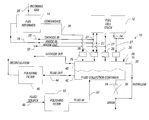
- FIG. 1 is a schematic diagram depicting a fluid recovery system in accordance with an embodiment of the present invention.
- FIG. 2 is a schematic diagram depicting another embodiment of a fluid recovery. system in accordance with the present invention.
- Fluid recovery system 10 comprises a fuel cell stack 12 , fuel reformer 14 , and fluid collection container 16 .
- Fuel cell stack 12 typically will include end plates and a working section therebetween (not shown).
- the working section may include one or more active sections and can include a selected number of cooling sections, as will be understood by those skilled in the art.
- the working section includes a number of individual fuel cells (not shown) which generally form fluid manifolds for supplying reactant gas. or fluids to, removing fluids from, and otherwise communicating and/or servicing fluids as desired within the working section.
- An anode gas supply line 18 and a cathode gas supply line 20 supply the reactant gases necessary for operation of the fuel cell system.
- Supply lines 18 and 20 may comprise a plurality of individual lines for supplying reactant gases to fuel cell stack 12 .
- Supply lines 18 and 20 may be preferably constructed from non-corrosive stainless-steel or polypropylene, or any other suitable material as may be known in the art.
- a reactant gas may be any substance which is classified as a fuel, such as substantially pure hydrogen, methanol reformate or natural gas reformate, or any substance classified as an oxidant such as substantially pure oxygen or oxygen containing air, as may be known in the art.
- Fuel cell stack 12 also preferably includes exhaust manifolds 22 and 24 for expelling unreacted fuel and oxidant gases.
- a gas supply line 28 carries the incoming gas, such as methanol or methane, to fuel reformer 14 .
- Fuel reformer 14 produces and introduces as a fuel, such as substantially pure hydrogen, methanol reformate or natural gas reformate, into anode supply line 18 , for use in fuel cell stack 12 .
- a condensate return line 30 transports condensate and/or fluid from fuel reformer 14 to fluid collection container 16 .
- Fluid collection container 16 may be constructed out of any suitable material, such as plastic or stainless steel. Those of skill in the art will appreciate that fluid collection container 16 may include traps 26 for collecting fluids condensing or accumulating in the system. Traps 26 are connected to various locations of the fuel cell system by fluid lines 27 . Traps 26 may have a needle and float arrangement, whereby transport of gas through traps 26 is blocked when there is no fluid in the trap. When fluid is in the trap, a float allows the fluid to enter fluid collection container 16 . Alternatively, any type of fluid trap may be used as is known in the art.
- Fluid collection container 16 may also have an overflow 32 and a drain 34 to aid in controlling the level of the fluid residing within fluid collection container 16 .
- Drain 34 may be operated by a valve 36 in communication with a level sensor (not shown) mounted within fluid collection container 16 . It will be appreciated by those of skill in the art that fluid and/or condensate may be transported to fluid collection container 16 from any area of the fuel cell system which fluid and/or condensate may be present. Also, multiple fluid collection containers may be used in conjunction with one another to afford greater design flexibility to the system.
- undesirable gas may become entrained or dissolved in the fluid being transported and ultimately reside in fluid collection container 16 .
- Build up of any undesirable gas, such as hydrogen, may present a hazard to operation of the system.
- Undesirable gas may be liberated during operation of the fuel cell by introducing a purge gas, such as air, into fluid collection container 16 .
- the purge gas enters fluid collection container 16 through inlet 38 , and exits along with any undesirable gas through outlet 40 .
- Inlet 38 and outlet 40 may comprise a valve capable of opening and closing depending on the operating conditions of the fuel cell system.
- the cathode exhaust stream may be utilized to purge fluid collection container 16 from the accumulation of any undesirable gases.
- this purge gas stream may then be sent to an oxidizer (not shown) such as a burner to remove any combustible gasses before the exhaust is vented to the atmosphere (as an example).
- an oxidizer such as a burner to remove any combustible gasses before the exhaust is vented to the atmosphere (as an example).
- outside air or a suitable purge gas from another source may be used to liberate any undesirable gas from fluid collection container 16 .
- the fluid collected in fluid collection container 16 may then be recirculated through the fuel cell system for use at various locations requiring such fluid.
- the fluid may exit fluid collection container 16 through an outlet 42 and into a fluid line 44 for recirculation.
- the fluid recovery system may have a polishing filter 46 connected to the recirculating fluid line.
- Polishing filter 46 may comprise a ResinTech filter model number mrn-1, for example, however any suitable polishing/scrubbing filter may be used as is known in the art.
- fluid will be required to be added to fluid recovery system 10 .
- fluid may be added from a source 48 (i.e. home water supply line) and deionized by use of a polishing filter 50 .
- Polishing filter 50 may be of similar construction to polishing filter 46 described herein. The fluid may then pass through fluid line 52 and into fluid collection container 16 for use by the system. In other embodiments, the fluid may not need to be filtered, or the degree of purity required may vary.
- Fluid recovery system 100 comprises a fluid collection container 116 , a fuel reformer 114 , an incoming reactant gas stream 110 , and a steam generator 118 .
- the present alternate embodiment may be utilized with a fuel cell system and contain components similar to those described with reference to FIG. 1.
- condensate is transported through fluid line 127 and is separated from the reactant gas streams by fluid trap 126 .
- the fluid then enters fluid collection container 116 .
- a reactant gas enters fluid collection container 116 through an inlet 120 .
- a steam generator 118 heats the fluid contained within fluid collection container 116 to create steam.
- Steam generator may comprise a heat exchanger, which uses heated coolant from a fuel cell system to generate the steam. Alternatively, any type of steam generator may be utilized as is known in the art.
- the humidified reactant gas then exits fluid collection container 116 through outlet 122 , and is transported via fluid line 124 to fuel reformer 114 .
- the steam to carbon ratio refers to the ratio of water molecules to carbon atoms in the gas phase. In one embodiment, this ratio may be achieved by adjusting the temperature of the mixed fuel and steam (above 70° C. for example). In other embodiments, the ratio may also be achieved by adjusting the rate of steam generated or by metering a desired amount of steam into the stream.
Landscapes
- Life Sciences & Earth Sciences (AREA)
- Engineering & Computer Science (AREA)
- Manufacturing & Machinery (AREA)
- Sustainable Development (AREA)
- Sustainable Energy (AREA)
- Chemical & Material Sciences (AREA)
- Chemical Kinetics & Catalysis (AREA)
- Electrochemistry (AREA)
- General Chemical & Material Sciences (AREA)
- Fuel Cell (AREA)
Abstract
Description
- This invention relates generally to fuel cells and, more particularly, to recovery of fluid for use by a fuel cell system.
- Fuel cells electrochemically convert fuels and oxidants to electricity. A Proton Exchange Membrane (hereinafter “PEM”) fuel cell converts the chemical energy of fuels such as hydrogen and oxidants such as air/oxygen directly into electrical energy. The PEM is a solid polymer electrolyte that permits the passage of protons (i.e., H + ions) from the “anode” side of a fuel cell to the “cathode” side of the fuel cell while preventing passage therethrough of reactant fluids (e.g., hydrogen and air/oxygen gases). The direction, from anode to cathode, of flow of protons serves as the basis for labeling an “anode” side and a “cathode” side of every layer in the fuel cell, and in the fuel cell assembly or stack.
- In general, an individual PEM-type fuel cell may have multiple, generally transversely extending layers assembled in a longitudinal direction. In a typical fuel cell assembly or stack, all layers which extend to the periphery of the fuel cells have holes therethrough for alignment and formation of fluid manifolds that generally service fluids for the stack. Typically, gaskets seal these holes and cooperate with the longitudinal extents of the layers for completion of the fluid supply manifolds. As may be known in the art, some of the fluid supply manifolds distribute fuel (e.g., hydrogen) and oxidant (e.g., air/oxygen) to, and remove unused fuel and oxidant as well as product water from, fluid flow plates which serve as flow field plates of each fuel cell. Other fluid supply manifolds circulate coolant (e.g., water) for cooling the fuel cell.
- In a typical PEM-type fuel cell, the membrane electrode assembly (hereinafter “MEA”) is sandwiched between “anode” and “cathode” gas diffusion layers (hereinafter “GDLs”) that can be formed from a resilient and conductive material such as carbon fabric or paper. The anode and cathode GDLs serve as electrochemical conductors between catalyzed sites of the PENI and the fuel (e.g., hydrogen) and oxidant (e.g., air/oxygen) which flow in respective “anode” and “cathode” flow channels of respective flow field plates.
- A typical fuel cell system generates condensate water at various locations within the system. Therefore, condensate traps have generally been designed and located at these locations to aid in the collection of condensate. The condensate may be collected and stored in a condensate accumulation container for future use by the system.
- Whereas, it may be undesirable to allow air to escape through the condensate traps, various arrangements have been designed to prevent air from escaping through the traps. For example, a needle and float arrangement may be utilized to allow condensate to escape when present, however the escape will be plugged when there is no condensate in the trap.
- It has been found that undesirable gasses may accumulate in the condensate collection container. Such gasses may become entrained or dissolved in the condensate removed in the system. The gasses may build up in the condensate collection container and present a hazard to the system. For example, a flammable gas such as hydrogen may accumulate in the condensate collection container and present a safety hazard to the system.
- The present invention provides a method for recovering fluid from a fuel cell system. The method includes providing the fuel cell system with a fluid collection container. The fluid collection container has a gas inlet and a gas outlet. The method further includes collecting condensate from the fuel cell system then transporting the condensate to the fluid collection container. A purge gas is provided to the gas inlet, wherein the purge gas flows through the fluid collection container and exits through the gas outlet.
- In another aspect, a method is provided for purging undesirable gas from a fluid container operating with a fuel cell system. The fluid container has an inlet and an outlet. The method includes providing a purge gas to the inlet. The purge gas flows through the fluid container and exits through the outlet.
- In another aspect, a fluid collection system is provided for a fuel cell system. The fluid collection device includes a fluid collection container which has a gas inlet, a gas outlet, at least one fluid inlet, and a fluid outlet. The at least one fluid inlet allows condensate to enter the fluid collection container. A fluid is contained within the fluid collection container. An undesirable gas is also contained within the fluid collection container. The as inlet allows a purge gas to enter the fluid collection container to substantially purge the undesirable gas out of the fluid collection container through the gas outlet.
- In another aspect, a method is provided for operating a fuel cell system. In general, water is separated from a reactant (process) stream and the water is collected in a collection or accumulation chamber. The atmosphere of the chamber is purged either continually or periodically. The water may be filtered to maintain a desired purity, and may be heated to generate water vapor (steam). The steam may be used, for example, to humidify a fuel processor inlet reactant stream to a desired steam to carbon ratio (3:1 for example). The steam to carbon ratio may be adjusted by adjusting the temperature of the humidified stream, by adjusting the amount of steam generated, and by metering the amount of steam introduced to the process stream (as examples). In some embodiments, the steam may be generated in a steam generator downstream from the fluid collection container (also referred to as an accumulation chamber). In other embodiments, the steam may be generated within the fluid collection container. In still other embodiments, the steam may be generated within the fluid collection container, and a fuel processor reactant gas may be used as the purge gas and be humidified by the steam. Other embodiments and features are possible and within the scope of the claims presented below.
- The subject matter that is regarded, as the invention is particularly pointed out and distinctly claimed in the claims at the conclusion of the specification. The foregoing and other features and advantages of the invention will be readily understood from the following detailed description of preferred embodiments taken in conjunction with the accompanying drawings in which:
- FIG. 1 is a schematic diagram depicting a fluid recovery system in accordance with an embodiment of the present invention.
- FIG. 2 is a schematic diagram depicting another embodiment of a fluid recovery. system in accordance with the present invention.
- Referring initially to FIG. 1 there is illustrated, in a schematic diagram, a fluid recovery system, generally referenced 10, that embodies the teachings of the present invention.
Fluid recovery system 10 comprises afuel cell stack 12,fuel reformer 14, andfluid collection container 16.Fuel cell stack 12 typically will include end plates and a working section therebetween (not shown). The working section may include one or more active sections and can include a selected number of cooling sections, as will be understood by those skilled in the art. - The working section includes a number of individual fuel cells (not shown) which generally form fluid manifolds for supplying reactant gas. or fluids to, removing fluids from, and otherwise communicating and/or servicing fluids as desired within the working section. An anode
gas supply line 18 and a cathodegas supply line 20 supply the reactant gases necessary for operation of the fuel cell system.Supply lines fuel cell stack 12.Supply lines - In the context of this invention a reactant gas may be any substance which is classified as a fuel, such as substantially pure hydrogen, methanol reformate or natural gas reformate, or any substance classified as an oxidant such as substantially pure oxygen or oxygen containing air, as may be known in the art.
Fuel cell stack 12 also preferably includesexhaust manifolds - A
gas supply line 28 carries the incoming gas, such as methanol or methane, to fuelreformer 14. Fuel reformer14 produces and introduces as a fuel, such as substantially pure hydrogen, methanol reformate or natural gas reformate, intoanode supply line 18, for use infuel cell stack 12. During fuel reformation condensate or excess fluid may be present infuel reformer 14, therefore the system may be equipped with acondensate return line 30.Condensate return line 30 transports condensate and/or fluid fromfuel reformer 14 tofluid collection container 16. -
Fluid collection container 16 may be constructed out of any suitable material, such as plastic or stainless steel. Those of skill in the art will appreciate thatfluid collection container 16 may includetraps 26 for collecting fluids condensing or accumulating in the system.Traps 26 are connected to various locations of the fuel cell system byfluid lines 27.Traps 26 may have a needle and float arrangement, whereby transport of gas throughtraps 26 is blocked when there is no fluid in the trap. When fluid is in the trap, a float allows the fluid to enterfluid collection container 16. Alternatively, any type of fluid trap may be used as is known in the art. -
Fluid collection container 16 may also have anoverflow 32 and adrain 34 to aid in controlling the level of the fluid residing withinfluid collection container 16.Drain 34 may be operated by avalve 36 in communication with a level sensor (not shown) mounted withinfluid collection container 16. It will be appreciated by those of skill in the art that fluid and/or condensate may be transported tofluid collection container 16 from any area of the fuel cell system which fluid and/or condensate may be present. Also, multiple fluid collection containers may be used in conjunction with one another to afford greater design flexibility to the system. - From time to time undesirable gas may become entrained or dissolved in the fluid being transported and ultimately reside in
fluid collection container 16. Build up of any undesirable gas, such as hydrogen, may present a hazard to operation of the system. Undesirable gas may be liberated during operation of the fuel cell by introducing a purge gas, such as air, intofluid collection container 16. The purge gas entersfluid collection container 16 throughinlet 38, and exits along with any undesirable gas throughoutlet 40.Inlet 38 andoutlet 40 may comprise a valve capable of opening and closing depending on the operating conditions of the fuel cell system. - As is shown in FIG. 1, the cathode exhaust stream may be utilized to purge
fluid collection container 16 from the accumulation of any undesirable gases. In some embodiments, this purge gas stream may then be sent to an oxidizer (not shown) such as a burner to remove any combustible gasses before the exhaust is vented to the atmosphere (as an example). Alternatively, outside air or a suitable purge gas from another source may be used to liberate any undesirable gas fromfluid collection container 16. - The fluid collected in
fluid collection container 16 may then be recirculated through the fuel cell system for use at various locations requiring such fluid. The fluid may exitfluid collection container 16 through anoutlet 42 and into afluid line 44 for recirculation. If the fluid collection container is collecting, for example, deionized water, purging the container may impart ions to the deionized water thereby rendering it conductive. Therefore, the fluid recovery system may have a polishingfilter 46 connected to the recirculating fluid line.Polishing filter 46 may comprise a ResinTech filter model number mrn-1, for example, however any suitable polishing/scrubbing filter may be used as is known in the art. - At various times of operation, such as start up, fluid will be required to be added to
fluid recovery system 10. When additional fluid is required to be added to the system, fluid may be added from a source 48 (i.e. home water supply line) and deionized by use of a polishingfilter 50.Polishing filter 50 may be of similar construction to polishingfilter 46 described herein. The fluid may then pass throughfluid line 52 and intofluid collection container 16 for use by the system. In other embodiments, the fluid may not need to be filtered, or the degree of purity required may vary. - An alternate embodiment of a fluid recovery system is illustrated is FIG. 2, in schematic format.
Fluid recovery system 100 comprises afluid collection container 116, afuel reformer 114, an incomingreactant gas stream 110, and asteam generator 118. In addition to the components depicted in FIG. 2, the present alternate embodiment may be utilized with a fuel cell system and contain components similar to those described with reference to FIG. 1. - As shown in FIG. 2, condensate is transported through
fluid line 127 and is separated from the reactant gas streams byfluid trap 126. The fluid then entersfluid collection container 116. A reactant gas entersfluid collection container 116 through aninlet 120. Asteam generator 118 heats the fluid contained withinfluid collection container 116 to create steam. Steam generator may comprise a heat exchanger, which uses heated coolant from a fuel cell system to generate the steam. Alternatively, any type of steam generator may be utilized as is known in the art. - The humidified reactant gas then exits
fluid collection container 116 throughoutlet 122, and is transported viafluid line 124 tofuel reformer 114. As will be appreciated by those of skill in the art, the particular fuel processing system that is used may dictate an optimal steam to carbon ratio, more than 2:1 for example, for a typical autothermal reforming system. The steam to carbon ratio refers to the ratio of water molecules to carbon atoms in the gas phase. In one embodiment, this ratio may be achieved by adjusting the temperature of the mixed fuel and steam (above 70° C. for example). In other embodiments, the ratio may also be achieved by adjusting the rate of steam generated or by metering a desired amount of steam into the stream. - Although preferred embodiments have been depicted and described in detail herein, it will be apparent to those skilled in the relevant art that various modifications, additions, substitutions and the like can be made without departing from the spirit of the invention and these are therefore considered to be within the scope of the invention as defined in the following claims.
Claims (29)
Priority Applications (1)
| Application Number | Priority Date | Filing Date | Title |
|---|---|---|---|
| US10/429,535 US7514165B2 (en) | 2000-07-31 | 2003-05-05 | Fuel cell system fluid recovery |
Applications Claiming Priority (2)
| Application Number | Priority Date | Filing Date | Title |
|---|---|---|---|
| US09/629,537 US6558826B1 (en) | 2000-07-31 | 2000-07-31 | Fuel cell system fluid recovery |
| US10/429,535 US7514165B2 (en) | 2000-07-31 | 2003-05-05 | Fuel cell system fluid recovery |
Related Parent Applications (1)
| Application Number | Title | Priority Date | Filing Date |
|---|---|---|---|
| US09/629,537 Division US6558826B1 (en) | 2000-07-31 | 2000-07-31 | Fuel cell system fluid recovery |
Publications (2)
| Publication Number | Publication Date |
|---|---|
| US20030198840A1 true US20030198840A1 (en) | 2003-10-23 |
| US7514165B2 US7514165B2 (en) | 2009-04-07 |
Family
ID=24523423
Family Applications (2)
| Application Number | Title | Priority Date | Filing Date |
|---|---|---|---|
| US09/629,537 Expired - Lifetime US6558826B1 (en) | 2000-07-31 | 2000-07-31 | Fuel cell system fluid recovery |
| US10/429,535 Expired - Lifetime US7514165B2 (en) | 2000-07-31 | 2003-05-05 | Fuel cell system fluid recovery |
Family Applications Before (1)
| Application Number | Title | Priority Date | Filing Date |
|---|---|---|---|
| US09/629,537 Expired - Lifetime US6558826B1 (en) | 2000-07-31 | 2000-07-31 | Fuel cell system fluid recovery |
Country Status (1)
| Country | Link |
|---|---|
| US (2) | US6558826B1 (en) |
Cited By (1)
| Publication number | Priority date | Publication date | Assignee | Title |
|---|---|---|---|---|
| US20230047889A1 (en) * | 2021-08-16 | 2023-02-16 | HyTech Power, Inc. | Hydrogen fuel cell exhaust system |
Families Citing this family (6)
| Publication number | Priority date | Publication date | Assignee | Title |
|---|---|---|---|---|
| US20030022036A1 (en) * | 2001-07-25 | 2003-01-30 | Ballard Power Systems Inc. | Fuel cell controller self inspection |
| US6953630B2 (en) | 2001-07-25 | 2005-10-11 | Ballard Power Systems Inc. | Fuel cell anomaly detection method and apparatus |
| US6979504B2 (en) * | 2001-07-25 | 2005-12-27 | Ballard Power Systems Inc. | Fuel cell system automatic power switching method and apparatus |
| WO2004021497A2 (en) * | 2002-08-07 | 2004-03-11 | Battelle Memorial Institute | Passive vapor exchange systems and techniques for fuel reforming and prevention of carbon fouling |
| US8246817B2 (en) * | 2004-06-10 | 2012-08-21 | Ford Motor Company | Deionization filter for fuel cell vehicle coolant |
| GB2514813B (en) * | 2013-06-05 | 2020-12-23 | Intelligent Energy Ltd | Fuel cell system and associated method of operation |
Citations (8)
| Publication number | Priority date | Publication date | Assignee | Title |
|---|---|---|---|---|
| US4037024A (en) * | 1973-02-09 | 1977-07-19 | The United States Of America As Represented By The Secretary Of The Navy | Fuel cell product-water management system |
| US5645950A (en) * | 1993-06-07 | 1997-07-08 | Daimler-Benz Ag | Process for supplying air to a fuel cell system |
| US5773160A (en) * | 1994-06-24 | 1998-06-30 | Ballard Power Systems Inc. | Electrochemical fuel cell stack with concurrent flow of coolant and oxidant streams and countercurrent flow of fuel and oxidant streams |
| US5922094A (en) * | 1996-12-11 | 1999-07-13 | Richards; Darrell | Water removal system |
| US6183895B1 (en) * | 1996-07-02 | 2001-02-06 | Matsushita Electric Works, Ltd. | Fuel-cell power generating system |
| US6316134B1 (en) * | 1999-09-13 | 2001-11-13 | Ballard Generation Systems, Inc. | Fuel cell electric power generation system |
| US6479177B1 (en) * | 1996-06-07 | 2002-11-12 | Ballard Power Systems Inc. | Method for improving the cold starting capability of an electrochemical fuel cell |
| US6579637B1 (en) * | 2000-05-31 | 2003-06-17 | General Motors Corporation | Fuel cell system having a compact water separator |
Family Cites Families (1)
| Publication number | Priority date | Publication date | Assignee | Title |
|---|---|---|---|---|
| US6348278B1 (en) * | 1998-06-09 | 2002-02-19 | Mobil Oil Corporation | Method and system for supplying hydrogen for use in fuel cells |
-
2000
- 2000-07-31 US US09/629,537 patent/US6558826B1/en not_active Expired - Lifetime
-
2003
- 2003-05-05 US US10/429,535 patent/US7514165B2/en not_active Expired - Lifetime
Patent Citations (8)
| Publication number | Priority date | Publication date | Assignee | Title |
|---|---|---|---|---|
| US4037024A (en) * | 1973-02-09 | 1977-07-19 | The United States Of America As Represented By The Secretary Of The Navy | Fuel cell product-water management system |
| US5645950A (en) * | 1993-06-07 | 1997-07-08 | Daimler-Benz Ag | Process for supplying air to a fuel cell system |
| US5773160A (en) * | 1994-06-24 | 1998-06-30 | Ballard Power Systems Inc. | Electrochemical fuel cell stack with concurrent flow of coolant and oxidant streams and countercurrent flow of fuel and oxidant streams |
| US6479177B1 (en) * | 1996-06-07 | 2002-11-12 | Ballard Power Systems Inc. | Method for improving the cold starting capability of an electrochemical fuel cell |
| US6183895B1 (en) * | 1996-07-02 | 2001-02-06 | Matsushita Electric Works, Ltd. | Fuel-cell power generating system |
| US5922094A (en) * | 1996-12-11 | 1999-07-13 | Richards; Darrell | Water removal system |
| US6316134B1 (en) * | 1999-09-13 | 2001-11-13 | Ballard Generation Systems, Inc. | Fuel cell electric power generation system |
| US6579637B1 (en) * | 2000-05-31 | 2003-06-17 | General Motors Corporation | Fuel cell system having a compact water separator |
Cited By (1)
| Publication number | Priority date | Publication date | Assignee | Title |
|---|---|---|---|---|
| US20230047889A1 (en) * | 2021-08-16 | 2023-02-16 | HyTech Power, Inc. | Hydrogen fuel cell exhaust system |
Also Published As
| Publication number | Publication date |
|---|---|
| US6558826B1 (en) | 2003-05-06 |
| US7514165B2 (en) | 2009-04-07 |
Similar Documents
| Publication | Publication Date | Title |
|---|---|---|
| US7833668B2 (en) | Fuel cell system with greater than 95% fuel utilization | |
| CN106104882B (en) | Fuel cell system | |
| US20100266923A1 (en) | Fuel cell system with electrochemical hydrogen pump and method of operating same | |
| KR101084072B1 (en) | Fuel cell system | |
| EP1276163B1 (en) | Solid polymer fuel cell | |
| US7883803B2 (en) | SOFC system producing reduced atmospheric carbon dioxide using a molten carbonated carbon dioxide pump | |
| US6207308B1 (en) | Water treatment system for a fuel cell assembly | |
| US7226680B2 (en) | Integrated air cooler, filter, and humidification unit for a fuel cell stack | |
| US6746789B1 (en) | Catalytic humidifier and heater for the fuel stream of a fuel cell | |
| US6706429B1 (en) | Catalytic humidifier and heater, primarily for humidification of the oxidant stream for a fuel cell | |
| US20090068512A1 (en) | Hydrogen refueling station | |
| KR20210132169A (en) | Solid oxide fuel cell system with hydrogen pumping cell with carbon monoxide tolerant anode and integrated shift reactor | |
| JP2011023168A (en) | Fuel cell system | |
| US20030118881A1 (en) | Method and apparatus for collecting condensate in an integrated fuel cell system | |
| US6558826B1 (en) | Fuel cell system fluid recovery | |
| JP2009064619A (en) | Fuel cell system | |
| US20070042237A1 (en) | Mixed reactant fuel cell system with vapor recovery and method of recovering vapor | |
| US20040197625A1 (en) | Method and apparatus for separating water from a fuel cell exhaust stream | |
| JP2001135338A (en) | Fuel cell device and method of operating fuel cell | |
| WO2004112180A1 (en) | Fuel cell cogeneration system | |
| JP2012109064A (en) | Fuel cell power generation system | |
| KR20090036014A (en) | Stack Purification Method of Fuel Cell System | |
| KR20140083729A (en) | Fuel cell vehicle with a hydrogen exhausting device | |
| JP2004213978A (en) | Fuel cell system | |
| JP2009245741A (en) | Method for stopping fuel cell power generator, and fuel cell power generator |
Legal Events
| Date | Code | Title | Description |
|---|---|---|---|
| STCF | Information on status: patent grant |
Free format text: PATENTED CASE |
|
| FPAY | Fee payment |
Year of fee payment: 4 |
|
| FEPP | Fee payment procedure |
Free format text: PAYOR NUMBER ASSIGNED (ORIGINAL EVENT CODE: ASPN); ENTITY STATUS OF PATENT OWNER: LARGE ENTITY |
|
| AS | Assignment |
Owner name: GENERATE LENDING, LLC, CALIFORNIA Free format text: SECURITY INTEREST;ASSIGNOR:PLUG POWER INC.;REEL/FRAME:038463/0132 Effective date: 20160321 |
|
| AS | Assignment |
Owner name: PLUG POWER INC., NEW YORK Free format text: RELEASE BY SECURED PARTY;ASSIGNOR:GENERATE LENDING, LLC;REEL/FRAME:039173/0300 Effective date: 20160627 |
|
| AS | Assignment |
Owner name: HERCULES CAPITAL, INC., CALIFORNIA Free format text: INTELLECTUAL PROPERTY SECURITY AGREEMENT;ASSIGNOR:PLUG POWER INC.;REEL/FRAME:039646/0065 Effective date: 20160627 |
|
| FPAY | Fee payment |
Year of fee payment: 8 |
|
| AS | Assignment |
Owner name: PLUG POWER INC., NEW YORK Free format text: RELEASE BY SECURED PARTY;ASSIGNOR:HERCULES CAPITAL, INC., AS AGENT;REEL/FRAME:041180/0709 Effective date: 20161222 Owner name: EMERGENT POWER INC., WASHINGTON Free format text: RELEASE BY SECURED PARTY;ASSIGNOR:HERCULES CAPITAL, INC., AS AGENT;REEL/FRAME:041180/0709 Effective date: 20161222 Owner name: EMERGING POWER INC., NEW YORK Free format text: RELEASE BY SECURED PARTY;ASSIGNOR:HERCULES CAPITAL, INC., AS AGENT;REEL/FRAME:041180/0709 Effective date: 20161222 |
|
| AS | Assignment |
Owner name: NY GREEN BANK, NEW YORK Free format text: SECURITY INTEREST;ASSIGNOR:PLUG POWER INC.;REEL/FRAME:041200/0623 Effective date: 20161223 |
|
| AS | Assignment |
Owner name: GENERATE LENDING, LLC, CALIFORNIA Free format text: SECURITY INTEREST;ASSIGNORS:PLUG POWER INC.;EMERGING POWER INC.;EMERGENT POWER INC.;REEL/FRAME:048751/0396 Effective date: 20190329 Owner name: PLUG POWER INC, NEW YORK Free format text: RELEASE BY SECURED PARTY;ASSIGNOR:NY GREEN BANK, A DIVISION OF THE NEW YORK STATE ENERGY RESEARCH AND DEVELOPMENT AUTHORITY;REEL/FRAME:048751/0844 Effective date: 20190329 Owner name: EMERGENT POWER INC., WASHINGTON Free format text: RELEASE BY SECURED PARTY;ASSIGNOR:NY GREEN BANK, A DIVISION OF THE NEW YORK STATE ENERGY RESEARCH AND DEVELOPMENT AUTHORITY;REEL/FRAME:048751/0844 Effective date: 20190329 Owner name: EMERGING POWER INC., NEW YORK Free format text: RELEASE BY SECURED PARTY;ASSIGNOR:NY GREEN BANK, A DIVISION OF THE NEW YORK STATE ENERGY RESEARCH AND DEVELOPMENT AUTHORITY;REEL/FRAME:048751/0844 Effective date: 20190329 |
|
| AS | Assignment |
Owner name: PLUG POWER INC., NEW YORK Free format text: ASSIGNMENT OF ASSIGNORS INTEREST;ASSIGNOR:WALSH, MICHAEL M.;REEL/FRAME:052078/0413 Effective date: 20001128 |
|
| FEPP | Fee payment procedure |
Free format text: ENTITY STATUS SET TO UNDISCOUNTED (ORIGINAL EVENT CODE: BIG.); ENTITY STATUS OF PATENT OWNER: LARGE ENTITY |
|
| MAFP | Maintenance fee payment |
Free format text: PAYMENT OF MAINTENANCE FEE, 12TH YEAR, LARGE ENTITY (ORIGINAL EVENT CODE: M1553); ENTITY STATUS OF PATENT OWNER: LARGE ENTITY Year of fee payment: 12 |