US20030198043A1 - Do-it-yourself lamp - Google Patents
Do-it-yourself lamp Download PDFInfo
- Publication number
- US20030198043A1 US20030198043A1 US10/127,149 US12714902A US2003198043A1 US 20030198043 A1 US20030198043 A1 US 20030198043A1 US 12714902 A US12714902 A US 12714902A US 2003198043 A1 US2003198043 A1 US 2003198043A1
- Authority
- US
- United States
- Prior art keywords
- seat
- lamp
- holes
- positioning disk
- stepped
- Prior art date
- Legal status (The legal status is an assumption and is not a legal conclusion. Google has not performed a legal analysis and makes no representation as to the accuracy of the status listed.)
- Granted
Links
- 238000004806 packaging method and process Methods 0.000 abstract description 4
- 238000003780 insertion Methods 0.000 description 2
- 230000037431 insertion Effects 0.000 description 2
- 230000007547 defect Effects 0.000 description 1
- 238000000034 method Methods 0.000 description 1
- 238000012986 modification Methods 0.000 description 1
- 230000004048 modification Effects 0.000 description 1
- 230000009466 transformation Effects 0.000 description 1
Images


Classifications
-
- F—MECHANICAL ENGINEERING; LIGHTING; HEATING; WEAPONS; BLASTING
- F21—LIGHTING
- F21S—NON-PORTABLE LIGHTING DEVICES; SYSTEMS THEREOF; VEHICLE LIGHTING DEVICES SPECIALLY ADAPTED FOR VEHICLE EXTERIORS
- F21S6/00—Lighting devices intended to be free-standing
- F21S6/002—Table lamps, e.g. for ambient lighting
- F21S6/003—Table lamps, e.g. for ambient lighting for task lighting, e.g. for reading or desk work, e.g. angle poise lamps
-
- F—MECHANICAL ENGINEERING; LIGHTING; HEATING; WEAPONS; BLASTING
- F21—LIGHTING
- F21S—NON-PORTABLE LIGHTING DEVICES; SYSTEMS THEREOF; VEHICLE LIGHTING DEVICES SPECIALLY ADAPTED FOR VEHICLE EXTERIORS
- F21S8/00—Lighting devices intended for fixed installation
-
- F—MECHANICAL ENGINEERING; LIGHTING; HEATING; WEAPONS; BLASTING
- F21—LIGHTING
- F21V—FUNCTIONAL FEATURES OR DETAILS OF LIGHTING DEVICES OR SYSTEMS THEREOF; STRUCTURAL COMBINATIONS OF LIGHTING DEVICES WITH OTHER ARTICLES, NOT OTHERWISE PROVIDED FOR
- F21V17/00—Fastening of component parts of lighting devices, e.g. shades, globes, refractors, reflectors, filters, screens, grids or protective cages
- F21V17/007—Fastening of component parts of lighting devices, e.g. shades, globes, refractors, reflectors, filters, screens, grids or protective cages with provision for shipment or storage
-
- F—MECHANICAL ENGINEERING; LIGHTING; HEATING; WEAPONS; BLASTING
- F21—LIGHTING
- F21V—FUNCTIONAL FEATURES OR DETAILS OF LIGHTING DEVICES OR SYSTEMS THEREOF; STRUCTURAL COMBINATIONS OF LIGHTING DEVICES WITH OTHER ARTICLES, NOT OTHERWISE PROVIDED FOR
- F21V23/00—Arrangement of electric circuit elements in or on lighting devices
- F21V23/06—Arrangement of electric circuit elements in or on lighting devices the elements being coupling devices, e.g. connectors
Definitions
- the present invention relates to lamp devices, and particularly to a do-it-yourself lamp, wherein in packaging, transferring, or storage, the lamp rod and seat can be separated for reducing the space required. Since the seat is assembled to a retaining tube of the seat, when the user buys the lamp, it is only necessary to insert the lamp rod into the seat for use. No other locking tool is necessary. Thereby, users can assembled the lamp rod and seat by himself (or herself).
- prior art lamps such as wall lamps, stand lamps, or ceiling lamps
- the studs and nuts are used as locking tools.
- the lamps are not only easily damaged, but also locking tools (such as spanners, or openers) are necessary in locking operation.
- locking tools such as spanners, or openers
- the electric wires are easily protruded out due to friction. Thereby, people easily get an electric shock.
- the prior art structure is not suitable to be assembled by users himself (or herself). The manufacturers must assembly the lamps in advance for sale. However, this will increase the space in transformation and storage and thus the cost is increased.
- the primary object of the present invention is to provide a do-it-yourself lamp which can improve the defects of the prior art, and the user can assemble the lamp structure by himself (or herself).
- a do-it-yourself lamp comprises a seat, and a lamp rod arranged on the seat.
- the seat has a plurality of penetrated stepped holes and a positioning disk.
- the positioning disk has a plurality of through holes aligned to the stepped holes but having a smaller diameter.
- a receptacle passes through one of the through holes.
- a plurality of locking holes are arranged between the through holes. Thereby, a locking stud passes through a ground wire and then passes through the locking hole of the positioning disk. Then, it is locked to a lower end of the seat.
- a bottom of the lamp rod is inserted with a joint in advance and one end portion of the joint is slightly protruded from the bottom end of the lamp rod.
- the end portion of the joint slightly protrudes from the bottom of the lamp rod is exactly inserted into the receptacle of the seat; the seat is conducted.
- the lamp rod and seat can be separated for reducing the space required. Since the seat is assembled to a retaining tube of the seat, when the user buys the seat, it is only necessary to insert the lamp rod into the seat for use. No other locking tool is necessary. Thereby, users can assembled the lamp rod and seat by himself (or herself).
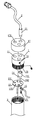
- FIG. 1 is an exploded perspective view of the present invention.
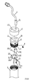
- FIG. 2 is an assembled perspective view of the present invention.
- FIG. 3A is a plane cross sectional view of the present invention before insertion.
- FIG. 3B is a plane cross sectional view of the present invention after insertion.
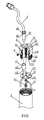
- FIG. 4 shows another embodiment of the present invention.
- FIG. 5 shows a further embodiment of the present invention.
- the do-it-yourself lamp of the present invention includes a seat 1 , and a lamp rod 2 arranged on the seat 1 .
- the interior of the seat 1 has a plurality of penetrated stepped holes 11 .
- a large stepped hole 11 A of each stepped hole 11 is exactly inserted by a receptacle 14
- the small stepped hole 11 B is exactly inserted by the joint 21 of the lamp rod 2 .
- At an edge of the seat 1 has a plurality of threaded holes 12 for tightening a confining stud P as the confining stud P is locked in the stepped holes.
- a cap 17 is installed upon a top surface of the seat 1 , and the cap 17 has a via hole 171 which is aligned to stepped holes 11 of the seat 1 .
- a lower end of the seat 1 is locked with a positioning disk 13 by a lock stud P 1 .
- the positioning disk 13 has a plurality of through holes 131 aligned to the stepped holes 11 but having a smaller diameter.
- the receptacle 14 can pass through one of the through holes 131 .
- a plurality of locking holes 132 are arranged between the through holes 131 . Thereby, the locking stud P 1 can pass through a ground wire 15 and then passes through the locking hole 132 of the positioning disk 13 . Then, it is locked to a lower end of the seat 1 .
- the edge of the receptacle 14 exactly resists against the positioning disk 13 for preventing the plug from falling out.
- the larger edge 141 of the receptacle 14 is exactly positioned in the stepped holes 11 of the seat 1 and the smaller edge 142 thereof is protruded from the lower end of the positioning disk 13 .
- the bottom of the seat 1 is installed with an outer threaded section 16 .
- the bottom of the lamp rod 2 is inserted with a joint 21 in advance and one end portion of the joint 21 is slightly protruded from the bottom of the lamp rod 2 .
- the end portion of the joint 21 slightly protruded from the bottom end of the lamp rod 2 is exactly inserted into the receptacle 14 of the seat 1 .
- the seat 1 is conducted.
- the positioning disk 13 is locked to a lower end of the seat 1 in advance, and the stepped holes in the seat 1 is positioned with a plug in advance.
- the plug 22 at a bottom of the lamp rod 2 is exactly inserted into the receptacle 13 of the seat 1 , so that the seat 1 is conductive to the lamp rod 2 .
- FIGS. 4 and 5 another two embodiments of the present invention are illustrated.
- the seat 1 A has penetrated stepped holes 11 .
- Each hole 11 has confining grooves 111 at two sides thereof.
- the receptacle 21 is exactly inserted into the large stepped hole 11 A of the seat 1 .
- a lower end of the seat 1 is locked with a positioning disk 13 by a lock stud P 1 .
- the positioning disk 13 has a plurality of through holes 131 at the center thereof and at positions aligned to the stepped holes 11 .
- the locking stud P 1 passes through a ground wire 15 and then passes through the through hole 131 at the center of the positioning disk 13 . Then, it is locked to a lower end of the seat 1 .
- the lamp rod 2 has a ring 22 conformed to the stepped holes 11 of the seat 1 and has a resisting block 23 conformed to the confining grooves 111 .
- the resisting block 23 exactly embeds to the confining groove 111 of the seat 1 for preventing the lamp rod 2 from rotation.
- the ring 22 of the lamp rod 2 exactly resists against a top end of the seat 1 for resisting against the lamp rod 2 from falling out (referring to FIG. 4).
- a top of the outer threaded section 16 of the seat 1 has a neck portion 161 . At a portion of the neck portion 161 exactly aligned an edge of the stepped holes 11 has a threaded hole 12 . Thereby, the confining stud P may be locked to tighten the plug 21 (referring to FIG. 5).
- the lamp rod 2 and seat 1 can be separated for reducing the space required. Since the seat 1 is assembled to a retaining tube of the seat 1 , when the user buys the seat 1 , it is only necessary to insert the lamp rod 2 into the seat 1 for use. No other locking tool is necessary. Thereby, users can assembled the lamp rod 2 and seat 1 by himself (or herself).
Landscapes
- Engineering & Computer Science (AREA)
- General Engineering & Computer Science (AREA)
- Non-Portable Lighting Devices Or Systems Thereof (AREA)
- Fastening Of Light Sources Or Lamp Holders (AREA)
Abstract
A do-it-yourself lamp comprises a seat, and a lamp rod arranged on the seat. The seat has a plurality of penetrated stepped holes and a positioning disk having a plurality of through holes. A receptacle passes through one of the through holes. A plurality of locking holes are arranged between the through holes. A bottom of the lamp rod is inserted with a joint and one end portion of the joint is slightly protruded from the bottom end of the lamp rod. After inserting the lamp rod, the end portion of the joint is exactly inserted into the receptacle for conducting the seat. In packaging, transferring, or storage, the lamp rod and seat can be separated for reducing the space. It is only necessary to insert the lamp rod into the seat for use. Thereby, users can assembled the lamp rod and seat by himself (or herself).
Description
- The present invention relates to lamp devices, and particularly to a do-it-yourself lamp, wherein in packaging, transferring, or storage, the lamp rod and seat can be separated for reducing the space required. Since the seat is assembled to a retaining tube of the seat, when the user buys the lamp, it is only necessary to insert the lamp rod into the seat for use. No other locking tool is necessary. Thereby, users can assembled the lamp rod and seat by himself (or herself).
- For prior art lamps, such as wall lamps, stand lamps, or ceiling lamps, the studs and nuts are used as locking tools. However, in such prior art locking method, the lamps are not only easily damaged, but also locking tools (such as spanners, or openers) are necessary in locking operation. In assembly, the electric wires are easily protruded out due to friction. Thereby, people easily get an electric shock. The prior art structure is not suitable to be assembled by users himself (or herself). The manufacturers must assembly the lamps in advance for sale. However, this will increase the space in transformation and storage and thus the cost is increased.
- Accordingly, the primary object of the present invention is to provide a do-it-yourself lamp which can improve the defects of the prior art, and the user can assemble the lamp structure by himself (or herself).
- To achieve above objects, the present invention provides a do-it-yourself lamp comprises a seat, and a lamp rod arranged on the seat. The seat has a plurality of penetrated stepped holes and a positioning disk. The positioning disk has a plurality of through holes aligned to the stepped holes but having a smaller diameter. A receptacle passes through one of the through holes. A plurality of locking holes are arranged between the through holes. Thereby, a locking stud passes through a ground wire and then passes through the locking hole of the positioning disk. Then, it is locked to a lower end of the seat. After the positioning disk is locked, a bottom of the lamp rod is inserted with a joint in advance and one end portion of the joint is slightly protruded from the bottom end of the lamp rod. After inserting the lamp rod, the end portion of the joint slightly protrudes from the bottom of the lamp rod is exactly inserted into the receptacle of the seat; the seat is conducted.
- Thereby, in packaging, transferring, or storage, the lamp rod and seat can be separated for reducing the space required. Since the seat is assembled to a retaining tube of the seat, when the user buys the seat, it is only necessary to insert the lamp rod into the seat for use. No other locking tool is necessary. Thereby, users can assembled the lamp rod and seat by himself (or herself).
- The various objects and advantages of the present invention will be more readily understood from the following detailed description when read in conjunction with the appended drawing.
- FIG. 1 is an exploded perspective view of the present invention.
- FIG. 2 is an assembled perspective view of the present invention.
- FIG. 3A is a plane cross sectional view of the present invention before insertion.
- FIG. 3B is a plane cross sectional view of the present invention after insertion.
- FIG. 4 shows another embodiment of the present invention.
- FIG. 5 shows a further embodiment of the present invention.
- Referring to FIG. 2, the structure of the do-it-yourself lamp of the present invention is illustrated. The do-it-yourself lamp of the present invention includes a seat 1, and a
lamp rod 2 arranged on the seat 1. - The interior of the seat 1 has a plurality of penetrated
stepped holes 11. A largestepped hole 11A of eachstepped hole 11 is exactly inserted by areceptacle 14, and the smallstepped hole 11B is exactly inserted by thejoint 21 of thelamp rod 2. At an edge of the seat 1 has a plurality of threadedholes 12 for tightening a confining stud P as the confining stud P is locked in the stepped holes. - A
cap 17 is installed upon a top surface of the seat 1, and thecap 17 has avia hole 171 which is aligned to steppedholes 11 of the seat 1. A lower end of the seat 1 is locked with apositioning disk 13 by a lock stud P1. Thepositioning disk 13 has a plurality of throughholes 131 aligned to thestepped holes 11 but having a smaller diameter. Thereceptacle 14 can pass through one of the throughholes 131. A plurality oflocking holes 132 are arranged between the throughholes 131. Thereby, the locking stud P1 can pass through aground wire 15 and then passes through thelocking hole 132 of thepositioning disk 13. Then, it is locked to a lower end of the seat 1. - After the
positioning disk 13 is locked, the edge of thereceptacle 14 exactly resists against thepositioning disk 13 for preventing the plug from falling out. Thelarger edge 141 of thereceptacle 14 is exactly positioned in thestepped holes 11 of the seat 1 and thesmaller edge 142 thereof is protruded from the lower end of thepositioning disk 13. The bottom of the seat 1 is installed with an outer threadedsection 16. After the seat 1 is assembled with thepositioning disk 13, thereceptacle 14 and theground wire 15, the outer threadedsection 16 of the seat 1 can be locked into theretaining tube 3 of a wall lamp, stand lamp or a ceiling lamp. - The bottom of the
lamp rod 2 is inserted with ajoint 21 in advance and one end portion of thejoint 21 is slightly protruded from the bottom of thelamp rod 2. After inserting thelamp rod 2, the end portion of thejoint 21 slightly protruded from the bottom end of thelamp rod 2 is exactly inserted into thereceptacle 14 of the seat 1. Thus, the seat 1 is conducted. - The operation of the present invention will be described herein with referring to FIG. 3. The
positioning disk 13 is locked to a lower end of the seat 1 in advance, and the stepped holes in the seat 1 is positioned with a plug in advance. When thelamp rod 2 inserts into the seat 1, theplug 22 at a bottom of thelamp rod 2 is exactly inserted into thereceptacle 13 of the seat 1, so that the seat 1 is conductive to thelamp rod 2. - Referring to FIGS. 4 and 5, another two embodiments of the present invention are illustrated. The
seat 1A has penetratedstepped holes 11. Eachhole 11 has confininggrooves 111 at two sides thereof. Thereby, thereceptacle 21 is exactly inserted into the largestepped hole 11A of the seat 1. A lower end of the seat 1 is locked with apositioning disk 13 by a lock stud P1. Thepositioning disk 13 has a plurality of throughholes 131 at the center thereof and at positions aligned to the stepped holes 11. The locking stud P1 passes through aground wire 15 and then passes through the throughhole 131 at the center of thepositioning disk 13. Then, it is locked to a lower end of the seat 1. - The
lamp rod 2 has aring 22 conformed to the steppedholes 11 of the seat 1 and has a resistingblock 23 conformed to the confininggrooves 111. Afterlamp rod 2 inserts into the seat 1, the resistingblock 23 exactly embeds to the confininggroove 111 of the seat 1 for preventing thelamp rod 2 from rotation. Thering 22 of thelamp rod 2 exactly resists against a top end of the seat 1 for resisting against thelamp rod 2 from falling out (referring to FIG. 4). - A top of the outer threaded
section 16 of the seat 1 has aneck portion 161. At a portion of theneck portion 161 exactly aligned an edge of the steppedholes 11 has a threadedhole 12. Thereby, the confining stud P may be locked to tighten the plug 21 (referring to FIG. 5). - Thereby, in packaging, transferring, or storage, the
lamp rod 2 and seat 1 can be separated for reducing the space required. Since the seat 1 is assembled to a retaining tube of the seat 1, when the user buys the seat 1, it is only necessary to insert thelamp rod 2 into the seat 1 for use. No other locking tool is necessary. Thereby, users can assembled thelamp rod 2 and seat 1 by himself (or herself). - The present invention is thus described, it will be obvious that the same may be varied in many ways. Such variations are not to be regarded as a departure from the spirit and scope of the present invention, and all such modifications as would be obvious to one skilled in the art are intended to be included within the scope of the following claims.
Claims (6)
1. A do-it-yourself lamp comprising a seat, and a lamp rod arranged on the seat; wherein
an interior of the seat has a plurality of penetrated stepped holes; a large stepped hole of each of the penetrated stepped holes is exactly inserted by a receptacle and a small stepped hole of each of the penetrated stepped holes is exactly inserted by a joint of the lamp rod;.
a lower end of the seat is locked with a positioning disk by a locking stud; the positioning disk has a plurality of through holes aligned to the stepped holes but having a smaller diameter; a receptacle passes through one of the through holes; a plurality of locking holes are arranged between the through holes; thereby, the locking stud passes through a ground wire and then passes through the locking hole of the positioning disk; then, it is locked to a lower end of the seat; after the positioning disk is locked, an edge of the receptacle exactly resists against the positioning disk for preventing the plug from falling out;. a larger edge of the receptacle is exactly positioned in the stepped holes of the seat and a smaller edge of the receptacle is protruded from a lower end of the positioning disk; a bottom of the seat is installed with an outer threaded section; and
a bottom of the lamp rod is inserted with a joint in advance and one end portion of the joint is slightly protruded from the bottom end of the lamp rod; after inserting the lamp rod, the end portion of the joint slightly protrudes from the bottom of the lamp rod is exactly inserted into the receptacle of the seat; the seat is conducted;
thereby, the space for transferring and storage is reduced, and in assembly, it is only necessary to insert lamp rod into the seat.
2. The do-it-yourself lamp as claimed in claim 1 , wherein each stepped hole has two confining grooves at two sides thereof; the positioning disk has a plurality of through holes at a center thereof and at positions aligned to the stepped holes; the locking stud passes through a ground wire and then passes through the through hole at the center of the positioning disk; thereby, locking to a lower end of the seat.
3. The do-it-yourself lamp as claimed in claim 1 , wherein the seat has a plurality of threaded hole each corresponding to respective stepped holes, thereby, a confining stud is inserted into the threaded hole to lock the plug.
4. The do-it-yourself lamp as claimed in claim 1 , wherein a top of the seat has a cap, the cap has a plurality of via holes corresponding to the stepped holes for covering the confining stud to prevent from falling out.
5. The do-it-yourself lamp as claimed in claim 1 , wherein an outer threaded section of the seat has a neck portion and an annular edge of the neck portion conforming to each stepped hole has a threaded hole; thereby, the confining stud is inserted into the threaded hole for tightening the plug.
6. The do-it-yourself lamp as claimed in claim 1 , wherein after the seat is assembled with the positioning disk, the receptacle and the ground wire, an outer threaded section of the seat is locked into a retaining tube of one of a wall lamp, stand lamp and a ceiling lamp.
Priority Applications (2)
| Application Number | Priority Date | Filing Date | Title |
|---|---|---|---|
| US10/127,149 US6655816B2 (en) | 2002-04-22 | 2002-04-22 | Do-it-yourself lamp |
| DE20208405U DE20208405U1 (en) | 2002-04-22 | 2002-05-31 | lamp |
Applications Claiming Priority (2)
| Application Number | Priority Date | Filing Date | Title |
|---|---|---|---|
| US10/127,149 US6655816B2 (en) | 2002-04-22 | 2002-04-22 | Do-it-yourself lamp |
| DE20208405U DE20208405U1 (en) | 2002-04-22 | 2002-05-31 | lamp |
Publications (2)
| Publication Number | Publication Date |
|---|---|
| US20030198043A1 true US20030198043A1 (en) | 2003-10-23 |
| US6655816B2 US6655816B2 (en) | 2003-12-02 |
Family
ID=30445072
Family Applications (1)
| Application Number | Title | Priority Date | Filing Date |
|---|---|---|---|
| US10/127,149 Expired - Fee Related US6655816B2 (en) | 2002-04-22 | 2002-04-22 | Do-it-yourself lamp |
Country Status (2)
| Country | Link |
|---|---|
| US (1) | US6655816B2 (en) |
| DE (1) | DE20208405U1 (en) |
Cited By (1)
| Publication number | Priority date | Publication date | Assignee | Title |
|---|---|---|---|---|
| USD956324S1 (en) * | 2020-11-03 | 2022-06-28 | Guilin Liu | Tree light |
Families Citing this family (7)
| Publication number | Priority date | Publication date | Assignee | Title |
|---|---|---|---|---|
| US6758577B2 (en) * | 2002-07-17 | 2004-07-06 | Wen-Chang Wu | Do-it-yourself lamp structure |
| US6948833B2 (en) * | 2003-06-03 | 2005-09-27 | Wen-Chang Wu | Ceiling lamp suspending device |
| US6831418B1 (en) * | 2003-06-16 | 2004-12-14 | Wen-Chang Wu | Rapid assembled and detached structure of lamp |
| CA2558567A1 (en) | 2005-09-06 | 2007-03-06 | The L.D. Kichler Co. | Bayonet connection for knock-down fixtures & portables |
| CN2886328Y (en) * | 2006-04-13 | 2007-04-04 | 刘淑丽 | A lamp head device |
| US9124044B2 (en) | 2012-11-02 | 2015-09-01 | Belpower Systems Llc | Electric plug system |
| US9178324B2 (en) * | 2012-11-02 | 2015-11-03 | Belpower Systems Llc | Electric plug system |
Family Cites Families (3)
| Publication number | Priority date | Publication date | Assignee | Title |
|---|---|---|---|---|
| US1623813A (en) * | 1924-10-14 | 1927-04-05 | Schell David | Combination fixture support and base |
| US5873652A (en) * | 1996-07-11 | 1999-02-23 | Schonbek Worldwide Lighting, Inc. | Chandlier assembly and chandelier components for glass arm configurations |
| DE29819156U1 (en) * | 1998-10-27 | 1999-01-14 | Lin, Jack, Taipeh/T'ai-pei | Desk lamp protector |
-
2002
- 2002-04-22 US US10/127,149 patent/US6655816B2/en not_active Expired - Fee Related
- 2002-05-31 DE DE20208405U patent/DE20208405U1/en not_active Expired - Lifetime
Cited By (1)
| Publication number | Priority date | Publication date | Assignee | Title |
|---|---|---|---|---|
| USD956324S1 (en) * | 2020-11-03 | 2022-06-28 | Guilin Liu | Tree light |
Also Published As
| Publication number | Publication date |
|---|---|
| DE20208405U1 (en) | 2002-09-19 |
| US6655816B2 (en) | 2003-12-02 |
Similar Documents
| Publication | Publication Date | Title |
|---|---|---|
| US6565240B1 (en) | Lamp connecting device capable of being assembled by users | |
| US6973858B2 (en) | Socket assembly that can be mounted and detached quickly | |
| US6666613B2 (en) | Easily assembled lamp retaining device | |
| US6715899B1 (en) | Easily assembled and detached wall lamp mounting device | |
| US6682303B2 (en) | Do-it-yourself ceiling fan with ceiling lamp | |
| US20040022062A1 (en) | Simple do-it myself lamb assembling structure | |
| US6655816B2 (en) | Do-it-yourself lamp | |
| US6986680B2 (en) | Conductive wire insertion device for installing a lamp rod | |
| US6489560B1 (en) | Positioning device of lamp rod used in ceiling lamp of wire box | |
| US6743978B2 (en) | Wire connection box with rapidly-assembled lamp rod | |
| US6685346B2 (en) | Do-it-yourself lamp rod | |
| US6692140B2 (en) | Lamp rod for mounting a lamp to a junction box | |
| US6589075B1 (en) | Device for rapidly assembling lamp rod and lamp seat | |
| US6758577B2 (en) | Do-it-yourself lamp structure | |
| US6600102B1 (en) | Wire connection device of ceiling lamp capable of being assembled by users | |
| US20020163813A1 (en) | Suspending and assembling structure for ceiling lamp | |
| US20050024883A1 (en) | Insertion structure for inserting lamp rod to wire winding box | |
| US20030139092A1 (en) | Synchronous conductive wire insertion device for lamp rod and wire connecting seat | |
| US6918686B2 (en) | Assembled lamp retaining device | |
| US6932501B2 (en) | Rapidly-assembled lamp with a detachable lamp rod and lamp seat | |
| US6617513B1 (en) | Lamp rod assembled device for assembling inserting rod into wire box | |
| US6831418B1 (en) | Rapid assembled and detached structure of lamp | |
| US6851829B2 (en) | Locking device for locking a lamp rod | |
| US7001040B2 (en) | Locking structure of ceiling lamp for locking ceiling lamp to wire winding box | |
| US6899447B2 (en) | Easily assembled lamp retaining device |
Legal Events
| Date | Code | Title | Description |
|---|---|---|---|
| FPAY | Fee payment |
Year of fee payment: 4 |
|
| REMI | Maintenance fee reminder mailed | ||
| LAPS | Lapse for failure to pay maintenance fees | ||
| STCH | Information on status: patent discontinuation |
Free format text: PATENT EXPIRED DUE TO NONPAYMENT OF MAINTENANCE FEES UNDER 37 CFR 1.362 |
|
| FP | Lapsed due to failure to pay maintenance fee |
Effective date: 20111202 |