US20030198037A1 - Backlighting module for a display apparatus - Google Patents
Backlighting module for a display apparatus Download PDFInfo
- Publication number
- US20030198037A1 US20030198037A1 US10/125,036 US12503602A US2003198037A1 US 20030198037 A1 US20030198037 A1 US 20030198037A1 US 12503602 A US12503602 A US 12503602A US 2003198037 A1 US2003198037 A1 US 2003198037A1
- Authority
- US
- United States
- Prior art keywords
- light
- plate body
- backlighting module
- light guide
- dielectric layer
- Prior art date
- Legal status (The legal status is an assumption and is not a legal conclusion. Google has not performed a legal analysis and makes no representation as to the accuracy of the status listed.)
- Granted
Links
Images


Classifications
-
- G—PHYSICS
- G02—OPTICS
- G02B—OPTICAL ELEMENTS, SYSTEMS OR APPARATUS
- G02B6/00—Light guides; Structural details of arrangements comprising light guides and other optical elements, e.g. couplings
- G02B6/0001—Light guides; Structural details of arrangements comprising light guides and other optical elements, e.g. couplings specially adapted for lighting devices or systems
- G02B6/0011—Light guides; Structural details of arrangements comprising light guides and other optical elements, e.g. couplings specially adapted for lighting devices or systems the light guides being planar or of plate-like form
- G02B6/0033—Means for improving the coupling-out of light from the light guide
- G02B6/005—Means for improving the coupling-out of light from the light guide provided by one optical element, or plurality thereof, placed on the light output side of the light guide
- G02B6/0053—Prismatic sheet or layer; Brightness enhancement element, sheet or layer
-
- G—PHYSICS
- G02—OPTICS
- G02B—OPTICAL ELEMENTS, SYSTEMS OR APPARATUS
- G02B6/00—Light guides; Structural details of arrangements comprising light guides and other optical elements, e.g. couplings
- G02B6/0001—Light guides; Structural details of arrangements comprising light guides and other optical elements, e.g. couplings specially adapted for lighting devices or systems
- G02B6/0011—Light guides; Structural details of arrangements comprising light guides and other optical elements, e.g. couplings specially adapted for lighting devices or systems the light guides being planar or of plate-like form
- G02B6/0065—Manufacturing aspects; Material aspects
-
- G—PHYSICS
- G02—OPTICS
- G02B—OPTICAL ELEMENTS, SYSTEMS OR APPARATUS
- G02B6/00—Light guides; Structural details of arrangements comprising light guides and other optical elements, e.g. couplings
- G02B6/0001—Light guides; Structural details of arrangements comprising light guides and other optical elements, e.g. couplings specially adapted for lighting devices or systems
- G02B6/0011—Light guides; Structural details of arrangements comprising light guides and other optical elements, e.g. couplings specially adapted for lighting devices or systems the light guides being planar or of plate-like form
- G02B6/0033—Means for improving the coupling-out of light from the light guide
- G02B6/0035—Means for improving the coupling-out of light from the light guide provided on the surface of the light guide or in the bulk of it
- G02B6/0036—2-D arrangement of prisms, protrusions, indentations or roughened surfaces
-
- G—PHYSICS
- G02—OPTICS
- G02B—OPTICAL ELEMENTS, SYSTEMS OR APPARATUS
- G02B6/00—Light guides; Structural details of arrangements comprising light guides and other optical elements, e.g. couplings
- G02B6/0001—Light guides; Structural details of arrangements comprising light guides and other optical elements, e.g. couplings specially adapted for lighting devices or systems
- G02B6/0011—Light guides; Structural details of arrangements comprising light guides and other optical elements, e.g. couplings specially adapted for lighting devices or systems the light guides being planar or of plate-like form
- G02B6/0033—Means for improving the coupling-out of light from the light guide
- G02B6/0035—Means for improving the coupling-out of light from the light guide provided on the surface of the light guide or in the bulk of it
- G02B6/0038—Linear indentations or grooves, e.g. arc-shaped grooves or meandering grooves, extending over the full length or width of the light guide
-
- G—PHYSICS
- G02—OPTICS
- G02B—OPTICAL ELEMENTS, SYSTEMS OR APPARATUS
- G02B6/00—Light guides; Structural details of arrangements comprising light guides and other optical elements, e.g. couplings
- G02B6/0001—Light guides; Structural details of arrangements comprising light guides and other optical elements, e.g. couplings specially adapted for lighting devices or systems
- G02B6/0011—Light guides; Structural details of arrangements comprising light guides and other optical elements, e.g. couplings specially adapted for lighting devices or systems the light guides being planar or of plate-like form
- G02B6/0033—Means for improving the coupling-out of light from the light guide
- G02B6/0035—Means for improving the coupling-out of light from the light guide provided on the surface of the light guide or in the bulk of it
- G02B6/0045—Means for improving the coupling-out of light from the light guide provided on the surface of the light guide or in the bulk of it by shaping at least a portion of the light guide
- G02B6/0046—Tapered light guide, e.g. wedge-shaped light guide
Definitions
- the invention relates to a display apparatus, more particularly to a backlighting module for a display apparatus.
- Backlighting modules are used to provide illuminating light to liquid crystal displays.
- a conventional backlighting module 1 is shown to include a linear light source 11 , a light guide 12 , a reflector plate 13 , a light diffuser 14 , and a prism unit 15 including two prisms 151 , 152 .
- the linear light source 11 is disposed adjacent to a light-incident end of the light guide 12 .
- Light from the linear light source 11 is radiated toward the light guide 12 or is reflected by a reflector 111 toward the light guide 12 .
- a reflector 111 toward the light guide 12 .
- the reflector plate 13 disposed beneath the light guide 12 , which cooperate to impair the total reflection phenomenon, light incident on the light guide 12 is diffused within a certain angular range at an upper light-emergent surface of the light guide 12 toward the light diffuser 14 in a relatively uniform distribution.
- the light further propagates through the light diffuser 14 and the prism unit 15 for viewing angle adjustment so that the illuminating light can spread out within a certain viewing angle range of a liquid crystal display (not shown).
- the shape and material of the light guide 12 determine the luminosity and uniformity of the light from the light-emergent surface of the light guide 12 .
- various methods of forming light guides of different constructions including injection molding, dot-printing, etching, cutting, sand blasting, etc.
- the optical elements in the light guide 12 include a plurality of elongated grooves 121 formed by cutting in the lower surface of the light guide 12 .
- Each of the grooves 121 extends in a direction transverse to the light propagating direction of the light source 11 .
- the light-emergent surface of the light guide 12 is also formed with a plurality of elongated grooves 122 that are transverse to the grooves 121 .
- the total reflection effect of the light guide 12 is destroyed by virtue of two reflective surfaces 123 of each of the grooves 121 , 122 .
- the thickness of the light guide 12 in general ranges from several hundredths of a millimeter to several millimeters.
- FIG. 3 illustrates the construction of another light guide 12 ′, which is formed with a plurality of micro-reflectors 125 on a lower surface thereof.
- the micro-reflectors 125 can also control the viewing angle distribution of the light emitted from the light-emergent surface of the light guide 12 ′. By controlling the number of the micro-reflectors 125 on the light guide 12 ′, the light emergent therefrom can be effectively modulated.
- the reflector plate 13 is required to reflect light escaping from the lower surface of the light guide 12 or 12 ′ back into the light guide 12 or 12 ′.
- the use of the reflector plate 13 increases the overall size and weight of the backlighting module 1 .
- a clearance though insignificantly small, is present between the reflector plate 13 and the light guide 12 ( 12 ′), there will be loss of light, which will reduce the rate of reflection.
- the main object of the present invention is to provide a backlighting module for a display apparatus, which includes a compact light guide that can reduce the overall size of the backlighting module and minimize undesirable loss of light to enhance the reflection rate.
- a backlighting module for a display apparatus includes:
- a light guide including a plate body disposed adjacent to the light source in a first direction corresponding to a light propagating direction of the light source, the plate body having first and second surfaces opposite to each other in a second direction that is transverse to the first direction, the light guide further including a dielectric layer formed on the first surface of the plate body, and a reflective layer formed on one side of the dielectric layer opposite to the first surface of the plate body, the dielectric layer having a refractive index smaller than that of the plate body, the light guide having a light incident end proximate to the light source in the first direction, wherein light from the light source enters into the light guide via the light incident end, is guided by the light guide toward the second surface of the plate body, and exits the light guide via the second surface of the plate body;
- a light diffuser disposed on the second surface of the plate body to receive and diffuse light that exits from the second surface of the plate body;
- a prism assembly disposed on the light diffuser to receive and distribute light from the light diffuser.
- FIG. 1 is a schematic exploded view of a conventional backlighting module
- FIG. 2 is an enlarged fragmentary schematic sectional view of a light guide of the conventional backlighting module
- FIG. 3 is an enlarged schematic side view of another conventional light guide
- FIG. 4 is a schematic exploded view of the first preferred embodiment of a backlighting module for a display apparatus according to the present invention
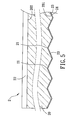
- FIG. 5 is an enlarged fragmentary schematic sectional view of a light guide employed in the backlighting module of the first preferred embodiment.
- FIG. 6 is an enlarged schematic side view of a light guide employed in the second preferred embodiment of a backlighting module for a display apparatus according to the present invention.
- the first preferred embodiment of a backlighting module 3 is to be employed in a display apparatus (not shown), such as a liquid crystal display, and is shown to include a reflector 30 , a linear light source 33 , a light guide 2 , a light diffuser 32 , and a prism assembly 31 .
- the linear light source 33 is surrounded by a curved reflecting surface 301 of the reflector 30 so that light propagates from the light source 33 along a first direction.
- the light guide 2 includes a plate body 20 disposed adjacent to the light source 33 in the first direction.
- the plate body 20 has first and second surfaces 201 , 202 opposite to each other in a second direction that is transverse to the first direction.
- FIG. 5 which is an enlarged view (not drawn to scale) of the light guide 2 , the first and second surfaces 201 , 202 of the plate body 20 are respectively formed with a plurality of elongated grooves 21 , 22 .
- the grooves 21 in the first surface 201 are transverse to the grooves 22 in the second surface 202 .
- the light guide 2 further includes a dielectric layer 23 formed on the first surface 201 , and a reflective layer 24 formed on one side of the dielectric layer 23 opposite to the first surface 201 .
- the dielectric layer 23 is formed by spin coating in a conventional manner, and has a thickness ranging from 10 to 40 micrometers.
- the dielectric layer 23 is formed from magnesium fluoride, which has a refractive index of 1.36, or silicon dioxide, which has a refractive index of 1.45).
- the reflective layer 24 is formed by sputtering in a conventional manner.
- the reflective layer 24 may be formed from a silvery white metal material, such as aluminum or silver.
- the reflective layer 24 may be formed from a white non-metal material, such as magnesium oxide or titanium oxide.
- the light guide 2 has a light incident end proximate to the light source 33 in the first direction. Light from the light source 33 enters into the light guide 2 via the light incident end, is guided by the light guide 2 toward the second surface 202 of the plate body 20 , and exits the light guide 2 via the second surface 202 .
- the light diffuser 32 is disposed on the second surface 202 of the plate body 20 so as to receive and diffuse the light that exits from the second surface 202 of the plate body 20 .
- the prism assembly 31 which includes superimposed first and second prisms 311 , 312 , is disposed on the light diffuser 32 to receive and distribute the light from the light diffuser 32 .
- the backlighting module can be made relatively compact and lightweight.
- FIG. 6 shows a modified light guide 4 of the second preferred embodiment of a backlighting module according to the present invention.
- the light guide 4 of this embodiment has a plurality of micro-reflectors 41 formed on a first surface 401 of a plate body 40 of the light guide 4 .
- a dielectric layer 42 and a reflective layer 43 are similarly formed on the first surface 401 in the same manner as described above to achieve the same advantages.
- the light guide according to the present invention can also be applied to those formed by etching, sand blasting or the like to achieve the aforesaid advantages of the present invention.
Landscapes
- Physics & Mathematics (AREA)
- General Physics & Mathematics (AREA)
- Optics & Photonics (AREA)
- Engineering & Computer Science (AREA)
- Manufacturing & Machinery (AREA)
- Planar Illumination Modules (AREA)
- Light Guides In General And Applications Therefor (AREA)
Abstract
Description
- 1. Field of the Invention
- The invention relates to a display apparatus, more particularly to a backlighting module for a display apparatus.
- 2. Description of the Related Art
- Backlighting modules are used to provide illuminating light to liquid crystal displays. Referring to FIG. 1, a conventional backlighting module 1 is shown to include a
linear light source 11, alight guide 12, areflector plate 13, alight diffuser 14, and aprism unit 15 including twoprisms - The
linear light source 11 is disposed adjacent to a light-incident end of thelight guide 12. Light from thelinear light source 11 is radiated toward thelight guide 12 or is reflected by areflector 111 toward thelight guide 12. By virtue of optical elements on a lower surface of thelight guide 12, and by virtue of thereflector plate 13 disposed beneath thelight guide 12, which cooperate to impair the total reflection phenomenon, light incident on thelight guide 12 is diffused within a certain angular range at an upper light-emergent surface of thelight guide 12 toward thelight diffuser 14 in a relatively uniform distribution. The light further propagates through thelight diffuser 14 and theprism unit 15 for viewing angle adjustment so that the illuminating light can spread out within a certain viewing angle range of a liquid crystal display (not shown). - As the
light guide 12 is the main light propagating medium in the backlighting module 1, the shape and material of thelight guide 12 determine the luminosity and uniformity of the light from the light-emergent surface of thelight guide 12. In order to enhance the luminosity and uniformity of the light from the light-emergent surface of thelight guide 12, there are available various methods of forming light guides of different constructions, including injection molding, dot-printing, etching, cutting, sand blasting, etc. - Referring to FIG. 2, the optical elements in the
light guide 12 include a plurality ofelongated grooves 121 formed by cutting in the lower surface of thelight guide 12. Each of thegrooves 121 extends in a direction transverse to the light propagating direction of thelight source 11. The light-emergent surface of thelight guide 12 is also formed with a plurality ofelongated grooves 122 that are transverse to thegrooves 121. The total reflection effect of thelight guide 12 is destroyed by virtue of tworeflective surfaces 123 of each of thegrooves - The thickness of the
light guide 12 in general ranges from several hundredths of a millimeter to several millimeters. Thegrooves grooves light guide 12. - FIG. 3 illustrates the construction of
another light guide 12′, which is formed with a plurality of micro-reflectors 125 on a lower surface thereof. Aside from contributing to the impairment of the total reflection effect of thelight guide 12′, the micro-reflectors 125 can also control the viewing angle distribution of the light emitted from the light-emergent surface of thelight guide 12′. By controlling the number of the micro-reflectors 125 on thelight guide 12′, the light emergent therefrom can be effectively modulated. - In the conventional backlighting module 1 of FIG. 1, the
reflector plate 13 is required to reflect light escaping from the lower surface of thelight guide light guide reflector plate 13 increases the overall size and weight of the backlighting module 1. Besides, as a clearance, though insignificantly small, is present between thereflector plate 13 and the light guide 12 (12′), there will be loss of light, which will reduce the rate of reflection. Hence, there is a need in the art for an improved backlighting module. - Therefore, the main object of the present invention is to provide a backlighting module for a display apparatus, which includes a compact light guide that can reduce the overall size of the backlighting module and minimize undesirable loss of light to enhance the reflection rate.
- According to the present invention, a backlighting module for a display apparatus includes:
- a linear light source;
- a light guide including a plate body disposed adjacent to the light source in a first direction corresponding to a light propagating direction of the light source, the plate body having first and second surfaces opposite to each other in a second direction that is transverse to the first direction, the light guide further including a dielectric layer formed on the first surface of the plate body, and a reflective layer formed on one side of the dielectric layer opposite to the first surface of the plate body, the dielectric layer having a refractive index smaller than that of the plate body, the light guide having a light incident end proximate to the light source in the first direction, wherein light from the light source enters into the light guide via the light incident end, is guided by the light guide toward the second surface of the plate body, and exits the light guide via the second surface of the plate body;
- a light diffuser disposed on the second surface of the plate body to receive and diffuse light that exits from the second surface of the plate body; and
- a prism assembly disposed on the light diffuser to receive and distribute light from the light diffuser.
- Other features and advantages of the present invention will become apparent in the following detailed description of the preferred embodiments with reference to the accompanying drawings, of which:
- FIG. 1 is a schematic exploded view of a conventional backlighting module;
- FIG. 2 is an enlarged fragmentary schematic sectional view of a light guide of the conventional backlighting module;
- FIG. 3 is an enlarged schematic side view of another conventional light guide;
- FIG. 4 is a schematic exploded view of the first preferred embodiment of a backlighting module for a display apparatus according to the present invention;
- FIG. 5 is an enlarged fragmentary schematic sectional view of a light guide employed in the backlighting module of the first preferred embodiment; and
- FIG. 6 is an enlarged schematic side view of a light guide employed in the second preferred embodiment of a backlighting module for a display apparatus according to the present invention.
- Referring to FIG. 4, the first preferred embodiment of a
backlighting module 3 according to the present invention is to be employed in a display apparatus (not shown), such as a liquid crystal display, and is shown to include areflector 30, alinear light source 33, alight guide 2, alight diffuser 32, and aprism assembly 31. - The
linear light source 33 is surrounded by a curved reflectingsurface 301 of thereflector 30 so that light propagates from thelight source 33 along a first direction. Thelight guide 2 includes aplate body 20 disposed adjacent to thelight source 33 in the first direction. Theplate body 20 has first andsecond surfaces light guide 2, the first andsecond surfaces plate body 20 are respectively formed with a plurality ofelongated grooves grooves 21 in thefirst surface 201 are transverse to thegrooves 22 in thesecond surface 202. In addition, thegrooves 21 in thefirst surface 201 are transverse to the first direction. Thelight guide 2 further includes adielectric layer 23 formed on thefirst surface 201, and areflective layer 24 formed on one side of thedielectric layer 23 opposite to thefirst surface 201. Thedielectric layer 23 is formed by spin coating in a conventional manner, and has a thickness ranging from 10 to 40 micrometers. In addition, thedielectric layer 23 has a refractive index smaller than the refractive index (n=1.49) of theplate body 20 for enhancing emission of light through thesecond surface 202 and luminance distribution. Preferably, thedielectric layer 23 is formed from magnesium fluoride, which has a refractive index of 1.36, or silicon dioxide, which has a refractive index of 1.45). Thereflective layer 24 is formed by sputtering in a conventional manner. Preferably, thereflective layer 24 is formed from a material that has good reflectivity and that has a light color, and has a thickness of about 100 Å (1 Å=10−10 m). Thereflective layer 24 may be formed from a silvery white metal material, such as aluminum or silver. Alternatively, thereflective layer 24 may be formed from a white non-metal material, such as magnesium oxide or titanium oxide. - Referring again to FIG. 4, the
light guide 2 has a light incident end proximate to thelight source 33 in the first direction. Light from thelight source 33 enters into thelight guide 2 via the light incident end, is guided by thelight guide 2 toward thesecond surface 202 of theplate body 20, and exits thelight guide 2 via thesecond surface 202. - The
light diffuser 32 is disposed on thesecond surface 202 of theplate body 20 so as to receive and diffuse the light that exits from thesecond surface 202 of theplate body 20. - The
prism assembly 31, which includes superimposed first andsecond prisms light diffuser 32 to receive and distribute the light from thelight diffuser 32. - In use, light from the
light source 33 enters the light incident end of thelight guide 2 and is reflected by thereflective layer 24 toward thesecond surface 202 of theplate body 20 for emission toward thelight diffuser 32. Since thedielectric layer 23 and thereflective layer 24 are an integral part of thelight guide 2, a gap will not be present so that loss of light is negligible and the rate of reflection is improved. As such, the present invention has the following advantages over the aforesaid prior art: - 1. As there is no need for a separate reflector plate, the number of components of the backlighting module can be reduced.
- 2. For the same reason, the backlighting module can be made relatively compact and lightweight.
- 3. As mentioned above, since the
reflective layer 24 is formed by sputtering, no gap will be present so that loss of light is minimized and the rate of reflection is enhanced. - FIG. 6 shows a modified light guide 4 of the second preferred embodiment of a backlighting module according to the present invention. Unlike the
light guide 2 of the previous embodiment, the light guide 4 of this embodiment has a plurality ofmicro-reflectors 41 formed on afirst surface 401 of aplate body 40 of the light guide 4. Adielectric layer 42 and areflective layer 43 are similarly formed on thefirst surface 401 in the same manner as described above to achieve the same advantages. - It is noted that the light guide according to the present invention can also be applied to those formed by etching, sand blasting or the like to achieve the aforesaid advantages of the present invention.
- While the present invention has been described in connection with what is considered the most practical and preferred embodiments, it is understood that this invention is not limited to the disclosed embodiments but is intended to cover various arrangements included within the spirit and scope of the broadest interpretation so as to encompass all such modifications and equivalent arrangements.
Claims (13)
Priority Applications (1)
| Application Number | Priority Date | Filing Date | Title |
|---|---|---|---|
| US10/125,036 US6705739B2 (en) | 2002-04-18 | 2002-04-18 | Backlighting module for a display apparatus |
Applications Claiming Priority (1)
| Application Number | Priority Date | Filing Date | Title |
|---|---|---|---|
| US10/125,036 US6705739B2 (en) | 2002-04-18 | 2002-04-18 | Backlighting module for a display apparatus |
Publications (2)
| Publication Number | Publication Date |
|---|---|
| US20030198037A1 true US20030198037A1 (en) | 2003-10-23 |
| US6705739B2 US6705739B2 (en) | 2004-03-16 |
Family
ID=29214706
Family Applications (1)
| Application Number | Title | Priority Date | Filing Date |
|---|---|---|---|
| US10/125,036 Expired - Fee Related US6705739B2 (en) | 2002-04-18 | 2002-04-18 | Backlighting module for a display apparatus |
Country Status (1)
| Country | Link |
|---|---|
| US (1) | US6705739B2 (en) |
Cited By (4)
| Publication number | Priority date | Publication date | Assignee | Title |
|---|---|---|---|---|
| US20070091637A1 (en) * | 2005-09-09 | 2007-04-26 | Enplas Corporation | Prism sheet, surface light source device and display |
| US20070127265A1 (en) * | 2004-04-12 | 2007-06-07 | Kuraray Co., Ltd. | Lighting system, image display apparatus using the same and light diffusion plate used therefor |
| EP2302938A3 (en) * | 2009-09-17 | 2014-11-26 | Lg Electronics Inc. | Mobile terminal |
| US20180143371A1 (en) * | 2015-05-15 | 2018-05-24 | Corning Incorporated | Glass article for illuminating a display panel |
Families Citing this family (7)
| Publication number | Priority date | Publication date | Assignee | Title |
|---|---|---|---|---|
| KR100926299B1 (en) * | 2002-11-13 | 2009-11-12 | 삼성전자주식회사 | Reflector for backlight assembly and backlight assembly using the same |
| JP2004179116A (en) * | 2002-11-29 | 2004-06-24 | Alps Electric Co Ltd | Backlighting device and liquid crystal display device |
| CN200968993Y (en) * | 2006-09-20 | 2007-10-31 | 鸿富锦精密工业(深圳)有限公司 | Light conducting plate and backlight module having the same |
| CN101334134A (en) * | 2008-07-23 | 2008-12-31 | 伟志光电(深圳)有限公司 | Light bar type LED lighting source |
| KR101607287B1 (en) * | 2008-11-07 | 2016-04-12 | 삼성디스플레이 주식회사 | Light guiding plate, backlight assembly and display apparatus having the same |
| KR20110020055A (en) * | 2009-08-21 | 2011-03-02 | 엘지이노텍 주식회사 | Backlight unit |
| US20130063965A1 (en) * | 2011-09-14 | 2013-03-14 | Shenzhen China Star Optoelectronics Technology Co.,Ltd. | Light guide plate and backlight module |
Citations (2)
| Publication number | Priority date | Publication date | Assignee | Title |
|---|---|---|---|---|
| US6196692B1 (en) * | 1998-04-17 | 2001-03-06 | Nitto Denko Corporation | Light conductive plate , surface light source device, and reflection type liquid-crystal display |
| US6364497B1 (en) * | 1999-03-24 | 2002-04-02 | L G Chemical Ltd. | Backlight system |
-
2002
- 2002-04-18 US US10/125,036 patent/US6705739B2/en not_active Expired - Fee Related
Patent Citations (2)
| Publication number | Priority date | Publication date | Assignee | Title |
|---|---|---|---|---|
| US6196692B1 (en) * | 1998-04-17 | 2001-03-06 | Nitto Denko Corporation | Light conductive plate , surface light source device, and reflection type liquid-crystal display |
| US6364497B1 (en) * | 1999-03-24 | 2002-04-02 | L G Chemical Ltd. | Backlight system |
Cited By (5)
| Publication number | Priority date | Publication date | Assignee | Title |
|---|---|---|---|---|
| US20070127265A1 (en) * | 2004-04-12 | 2007-06-07 | Kuraray Co., Ltd. | Lighting system, image display apparatus using the same and light diffusion plate used therefor |
| US7556393B2 (en) * | 2004-04-12 | 2009-07-07 | Kuraray Co., Ltd. | Lighting system, image display apparatus using the same and light diffusion plate used therefor |
| US20070091637A1 (en) * | 2005-09-09 | 2007-04-26 | Enplas Corporation | Prism sheet, surface light source device and display |
| EP2302938A3 (en) * | 2009-09-17 | 2014-11-26 | Lg Electronics Inc. | Mobile terminal |
| US20180143371A1 (en) * | 2015-05-15 | 2018-05-24 | Corning Incorporated | Glass article for illuminating a display panel |
Also Published As
| Publication number | Publication date |
|---|---|
| US6705739B2 (en) | 2004-03-16 |
Similar Documents
| Publication | Publication Date | Title |
|---|---|---|
| US6824285B2 (en) | Light source and liquid crystal display device using this light source | |
| KR100436104B1 (en) | Illuminator, liquid crystal display using the illuminator and electronic device | |
| US7275850B2 (en) | Backlight unit | |
| US7873256B2 (en) | Backlight with structured surfaces | |
| JP4533728B2 (en) | Liquid crystal display | |
| JP3301752B2 (en) | Front light, reflective liquid crystal display device and portable information terminal | |
| CN100504464C (en) | Surface light source device | |
| US20010001595A1 (en) | Backlight assembly with a light pipe having optical elements and an integral surface diffuser | |
| KR20030061844A (en) | Light source device | |
| JP3955505B2 (en) | Light guide plate | |
| JPH05203947A (en) | Plane luminous body device | |
| JPWO1997017631A1 (en) | Illumination device, and liquid crystal display device and electronic device using the same | |
| US20060262568A1 (en) | Front light for diffusely reflecting displays | |
| US6705739B2 (en) | Backlighting module for a display apparatus | |
| JP2003100128A (en) | Planar lighting device | |
| US20090303414A1 (en) | Optical member with a scatter layer, and backlight assembly and display device having the same | |
| JP4671344B2 (en) | Light guide plate and backlight device using the same | |
| JP3703250B2 (en) | Reflective display lighting device | |
| JP2000227522A (en) | Light guide plate and flat lighting device | |
| JPH09292531A (en) | Light guide plate, light deflection plate, and flat illumination device | |
| JP4350009B2 (en) | Surface light emitting device and liquid crystal display device | |
| JPH1073820A (en) | Non-light-diffusing light guide plate, lens film, and surface light source device | |
| US6585386B1 (en) | Light pipe, surface light source device and reflection type liquid-crystal display device | |
| JP2003114432A (en) | Surface light source device and light guide used therein | |
| JP4421583B2 (en) | Light guide plate and surface light emitting device |
Legal Events
| Date | Code | Title | Description |
|---|---|---|---|
| AS | Assignment |
Owner name: HELIS TECHNOLOGY INC., TAIWAN Free format text: ASSIGNMENT OF ASSIGNORS INTEREST;ASSIGNOR:KUO, CHUNG-YU;REEL/FRAME:012825/0798 Effective date: 20020403 |
|
| AS | Assignment |
Owner name: HELIX TECHNOLOGY INC., TAIWAN Free format text: REQUEST TO CORRECT REEL/FRAME;ASSIGNOR:KUO, CHUNG-YU;REEL/FRAME:013341/0832 Effective date: 20020403 |
|
| REMI | Maintenance fee reminder mailed | ||
| LAPS | Lapse for failure to pay maintenance fees | ||
| LAPS | Lapse for failure to pay maintenance fees |
Free format text: PATENT EXPIRED FOR FAILURE TO PAY MAINTENANCE FEES (ORIGINAL EVENT CODE: EXP.); ENTITY STATUS OF PATENT OWNER: SMALL ENTITY |
|
| STCH | Information on status: patent discontinuation |
Free format text: PATENT EXPIRED DUE TO NONPAYMENT OF MAINTENANCE FEES UNDER 37 CFR 1.362 |
|
| FP | Lapsed due to failure to pay maintenance fee |
Effective date: 20080316 |