US20030198029A1 - Pluggable optical transceiver with push-pull actuator handle - Google Patents
Pluggable optical transceiver with push-pull actuator handle Download PDFInfo
- Publication number
- US20030198029A1 US20030198029A1 US10/249,249 US24924903A US2003198029A1 US 20030198029 A1 US20030198029 A1 US 20030198029A1 US 24924903 A US24924903 A US 24924903A US 2003198029 A1 US2003198029 A1 US 2003198029A1
- Authority
- US
- United States
- Prior art keywords
- transceiver
- receptacle
- slide member
- actuator
- slide
- Prior art date
- Legal status (The legal status is an assumption and is not a legal conclusion. Google has not performed a legal analysis and makes no representation as to the accuracy of the status listed.)
- Granted
Links
- 230000003287 optical effect Effects 0.000 title claims abstract description 16
- 239000000835 fiber Substances 0.000 claims description 10
- 230000006835 compression Effects 0.000 description 3
- 238000007906 compression Methods 0.000 description 3
- 230000008901 benefit Effects 0.000 description 2
- 230000000712 assembly Effects 0.000 description 1
- 238000000429 assembly Methods 0.000 description 1
- 238000011161 development Methods 0.000 description 1
- 238000003780 insertion Methods 0.000 description 1
- 230000037431 insertion Effects 0.000 description 1
- 238000004519 manufacturing process Methods 0.000 description 1
- 230000007246 mechanism Effects 0.000 description 1
- 238000000034 method Methods 0.000 description 1
- 238000012986 modification Methods 0.000 description 1
- 230000004048 modification Effects 0.000 description 1
- 230000008707 rearrangement Effects 0.000 description 1
- 230000000717 retained effect Effects 0.000 description 1
- 238000012552 review Methods 0.000 description 1
- 238000012358 sourcing Methods 0.000 description 1
Images


Classifications
-
- G—PHYSICS
- G02—OPTICS
- G02B—OPTICAL ELEMENTS, SYSTEMS OR APPARATUS
- G02B6/00—Light guides; Structural details of arrangements comprising light guides and other optical elements, e.g. couplings
- G02B6/24—Coupling light guides
- G02B6/42—Coupling light guides with opto-electronic elements
- G02B6/4201—Packages, e.g. shape, construction, internal or external details
- G02B6/4274—Electrical aspects
- G02B6/4277—Protection against electromagnetic interference [EMI], e.g. shielding means
-
- G—PHYSICS
- G02—OPTICS
- G02B—OPTICAL ELEMENTS, SYSTEMS OR APPARATUS
- G02B6/00—Light guides; Structural details of arrangements comprising light guides and other optical elements, e.g. couplings
- G02B6/24—Coupling light guides
- G02B6/42—Coupling light guides with opto-electronic elements
- G02B6/4201—Packages, e.g. shape, construction, internal or external details
- G02B6/4246—Bidirectionally operating package structures
-
- G—PHYSICS
- G02—OPTICS
- G02B—OPTICAL ELEMENTS, SYSTEMS OR APPARATUS
- G02B6/00—Light guides; Structural details of arrangements comprising light guides and other optical elements, e.g. couplings
- G02B6/24—Coupling light guides
- G02B6/36—Mechanical coupling means
- G02B6/38—Mechanical coupling means having fibre to fibre mating means
- G02B6/3807—Dismountable connectors, i.e. comprising plugs
- G02B6/381—Dismountable connectors, i.e. comprising plugs of the ferrule type, e.g. fibre ends embedded in ferrules, connecting a pair of fibres
- G02B6/3825—Dismountable connectors, i.e. comprising plugs of the ferrule type, e.g. fibre ends embedded in ferrules, connecting a pair of fibres with an intermediate part, e.g. adapter, receptacle, linking two plugs
-
- G—PHYSICS
- G02—OPTICS
- G02B—OPTICAL ELEMENTS, SYSTEMS OR APPARATUS
- G02B6/00—Light guides; Structural details of arrangements comprising light guides and other optical elements, e.g. couplings
- G02B6/24—Coupling light guides
- G02B6/36—Mechanical coupling means
- G02B6/38—Mechanical coupling means having fibre to fibre mating means
- G02B6/3807—Dismountable connectors, i.e. comprising plugs
- G02B6/389—Dismountable connectors, i.e. comprising plugs characterised by the method of fastening connecting plugs and sockets, e.g. screw- or nut-lock, snap-in, bayonet type
- G02B6/3893—Push-pull type, e.g. snap-in, push-on
-
- H—ELECTRICITY
- H01—ELECTRIC ELEMENTS
- H01R—ELECTRICALLY-CONDUCTIVE CONNECTIONS; STRUCTURAL ASSOCIATIONS OF A PLURALITY OF MUTUALLY-INSULATED ELECTRICAL CONNECTING ELEMENTS; COUPLING DEVICES; CURRENT COLLECTORS
- H01R13/00—Details of coupling devices of the kinds covered by groups H01R12/70 or H01R24/00 - H01R33/00
- H01R13/62—Means for facilitating engagement or disengagement of coupling parts or for holding them in engagement
- H01R13/629—Additional means for facilitating engagement or disengagement of coupling parts, e.g. aligning or guiding means, levers, gas pressure electrical locking indicators, manufacturing tolerances
- H01R13/633—Additional means for facilitating engagement or disengagement of coupling parts, e.g. aligning or guiding means, levers, gas pressure electrical locking indicators, manufacturing tolerances for disengagement only
- H01R13/6335—Additional means for facilitating engagement or disengagement of coupling parts, e.g. aligning or guiding means, levers, gas pressure electrical locking indicators, manufacturing tolerances for disengagement only comprising a handle
Definitions
- the present invention relates generally to pluggable optical transceivers.
- the invention relates to a push-pull actuator handle for quickly and easily removing a small form factor pluggable (SFP) transceiver from a transceiver-receptacle cage assembly.
- SFP small form factor pluggable
- Pluggable optical transceivers are known in the art, and have been the subject of various industry standards and sourcing agreements between common vendors. In particular, multiple vendors have entered into a multi-source agreement (MSA) setting forth common standards and specifications for small form factor pluggable (SFP) transceivers.
- MSA multi-source agreement
- an optical transceiver is an integrated fiber optic component including an optical transmitter and an optical receiver.
- the pluggable transceiver includes a first end with a fiber optic connector and a second end with an electrical connector.
- the fiber optical connector is a LC-type duplex connector.
- the electrical connector is a card edge connector that is received into a female electrical connector housed inside a receptacle.
- the receptacle assembly is mounted on a daughter card of a host system.
- a common mechanical and electrical outline for the SFP transceiver is defined by the MSA. However, each individual manufacturer (vendor) is responsible for its own development and manufacturing of the SFP transceiver including developing a method for releasing and removing the transceiver from the receptacle assembly.
- the MSA provides some specifications for securing the transceiver to the receptacle cage. Particularly, the MSA specifies a spring-loaded latching tab in the receptacle that engages a standard locking detent on the bottom surface of the transceiver. When the transceiver is slidably inserted into the receptacle, the detent engages the latching tab and the transceiver is physically retained in place by the interlocking engagement of the detent to the latching tab.
- the MSA does not provide any standard mechanisms for releasing and removing the transceiver from the receptacle cage.
- the present invention provides a novel actuator assembly for disengaging the latching tab from the detent, thus allowing a person to easily remove the transceiver from the receptacle.
- the actuator assembly of the present invention comprises several components.
- One component is a slide member slidably mounted on the bottom surface of the transceiver.
- the slide member is located adjacent to a locking detent on the transceiver housing.
- the slide member has a forward-facing end, a rear-facing end, and two opposing side portions.
- the rear end of the slide member has angled cam surfaces for selectively engaging the latching tab on the receptacle cage.
- the forward end of the slide member has an actuator handle projecting therefrom.
- the actuator handle has a loop structure comprising two lateral (side) segments integrally connected by a curved segment.
- the actuator assembly further comprises a pair of opposing cantilevered spring arms, each spring arm extending along a side portion of the slide member.
- the cantilevered spring arms engage with posts on the housing in two positions, an inner position and an outer position.
- the posts are formed within a channel on the bottom of the transceiver housing and the spring arms slide between positions forward and rearward of the posts.
- the angled cam surfaces of the slide member are maintained forwardly of the latching tab so that the latching tab engages the latching detent and the transceiver remains engaged with the receptacle cage.
- the angled cam surfaces are maintained in a rearward position for engagement with the latching tab of the receptacle cage.
- the actuator handle i.e. spring arms are
- the transceiver module can be locked in the receptacle cage.
- the slide member remains in this initial locked (outer) position, until sufficient force is applied to the slide member that causes it to slide rearward over the posts and into the inner position wherein the angled cam surfaces engage the latching tab in the receptacle cage.
- an optical transceiver module having an integrated actuator assembly
- providing an actuator assembly having an actuator handle with a loop structure providing an actuator assembly that can be pushed and pulled in a linear direction
- FIG. 1 is a bottom perspective view showing three (3) separate transceiver modules, A, B, and C, inserted in three (3) separate receptacle cages in a side-by-side arrangement, wherein each transceiver has an actuator assembly in accordance with the present invention and the actuator assemblies are shown in different positions;
- FIG. 2 is a top and side perspective view of the three (3) transceiver modules and receptacle cages illustrated in FIG. 1;
- FIG. 3 is a bottom perspective view showing a transceiver module of the present invention in a locked, position in a receptacle cage;
- FIG. 4 is a bottom perspective view showing a transceiver module of the present invention in an unlocked position in a receptacle cage
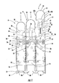
- FIG. 5 is an exploded view showing a transceiver module, actuator assembly, and receptacle cage in accordance with the present invention.
- the pluggable transceiver module of the instant invention is illustrated and generally indicated at 10 in FIGS. 1 - 5 .
- the instant small format pluggable (SFP) transceiver module 10 includes an integrated actuator assembly generally indicated at 12 for disengaging the transceiver 10 from a corresponding receptacle cage generally indicated at 14 .
- the optical transceiver module 10 is essentially an integrated fiber optic component including an optical transmitter and optical receiver (not shown).
- the pluggable transceiver 10 includes a plastic housing frame 16 having a first end 46 with fiber optic connector ports 18 located therein, and an opposite second end 48 with an electrical edge connector (not shown) projecting therefrom.
- the fiber optic connector ports 18 are an LC-type duplex connector.
- the housing 16 of the transceiver 10 includes an upper (top) surface 50 (FIG. 2) and a lower (bottom) surface 52 (FIG. 1).
- the bottom surface 52 of the housing 16 includes a slide member 28 and a locking detent 26 as illustrated in FIG. 1.
- the locking detent 26 secures the transceiver 10 within the receptacle cage 14 as described in further detail below.
- the optical transmitter and optical receiver are mounted on a circuit board (not shown) that is received inside the housing frame 16 of the transceiver 10 .
- the rear edge of the circuit board forms the electrical edge connector (not shown).
- a metallic cover encloses the top surface 50 of housing frame 16 and provides electromagnetic interference (EMI) shielding and case grounding to the chassis ground.
- a portion of the bottom surface 52 of the housing 16 is enclosed by a separate plastic cover (not shown).
- the outer dimensions of the male plug end of the LC-type duplex fiber optic cable are standard, and therefore the corresponding female fiber optic connector ports must also be standard dimensions.
- the first end 46 of the housing frame 16 is generally rectangular, slightly longer side-to-side, when viewed from the front. The width and height of the housing frame 16 are fixed by SFP standards.
- the two connector ports 18 are symmetrically positioned and arranged within the rectangular outline. Latching surfaces are provided within the connector ports 18 to permit engagement with the standard latch members of the fiber optic cable.
- the arrangement and operation of the actuator assembly 12 mounted on the first end 46 of the transceiver housing 16 is further described below.
- the electrical edge connector is received into a female electrical connector housed inside the receptacle assembly which is in turn mounted on a daughter card of a host system (not shown).
- the receptacle cage 14 includes kick-out springs 20 located at the rear end 54 of the cage 14 which engage the rear end 48 of the transceiver 10 and bias the transceiver 10 outwardly.
- a spring-loaded latching tab 22 is located at the open forward end 56 of the receptacle cage 14 .
- the latching tab 22 includes an opening or aperture 24 therein for locking the detent 26 of the transceiver 10 .
- the opening 24 is shown as having a triangular shape, but other designed openings may also be suitable.
- the transceiver 10 slides into the receptacle cage 14 and the locking detent 26 catches and locks with the opening 24 in the latching tab 22 .
- the transceiver 10 is secured to the receptacle 14 by means of locking detent 26 engaging and entering the opening 24 in the latching tab 22 . In this manner, the transceiver 10 is locked within the receptacle 14 .
- Transceiver “B” is shown locked in the receptacle cage 14 . With Transceiver B, the actuator handle 34 has been pulled outwardly, and the actuator assembly 12 is in an outer, locked position. The transceiver 10 and actuator assembly 12 are also shown in an outer, locked position in FIG. 3.
- a person can insert the transceiver module 10 into the receptacle cage 14 by pushing the transceiver 10 into the cage 14 until he or she feels the resistance of the kick-out springs 20 located at the rear of the cage 14 . Then, the person should push the transceiver 10 further until feeling the “click” of the detent 26 locking with the opening 24 . In the locked position, the cantilever spring arms 36 of the actuator assembly 12 are engaged with post members 38 on the transceiver housing 16 as further described below.
- the transceiver 10 of the present invention includes an actuator assembly 12 .
- the actuator assembly 12 comprises several components, particularly a slide member 28 and an actuator handle 34 .
- the slide member 28 is located adjacent to the locking detent 26 on the bottom surface 52 of the transceiver 10 . Particularly, the slide member 28 slides within channel structure 30 as shown in Transceiver “C” of FIG. 1 and in FIG. 4.
- the slide member 28 has a forward-facing end 58 , a rear-facing end 60 , and two opposing side ends 61 as illustrated in Transceiver C of FIG. 1.
- the rear end 60 of the slide member 28 has angled cam surfaces 32 which are operative for engaging the latching tab 22 to move the latching tab 22 out of engagement with the detent 26 .
- the forward end 58 of the slide member 28 includes an actuator handle or loop 34 projecting therefrom.
- the actuator handle 34 has a loop structure comprising two lateral (side) segments 62 a and 62 b integrally connected by a curved segment 64 .
- the actuator assembly 12 further comprises a pair of opposing cantilevered spring arms 36 , each spring arm 36 being adjacent to a side end 61 of the slide member 28 .
- the cantilevered spring arms 36 engage with triangular posts 38 on the housing in two positions, an inner position, as shown with Transceiver A in FIG. 1 and FIG. 4, and an outer position as shown with Transceiver B in FIG. 1 and FIG. 3.
- the posts 38 are formed within a channel on the bottom of the transceiver housing 16 and the spring arms 36 slide between positions forward (outer position) and rearward (inner position) of the posts 38 . In the outer position (FIG.
- the angled cam surfaces 32 of the slide member 28 are maintained forwardly of the latching tab 22 so that the latching tab 22 engages the latching detent 26 and the transceiver 10 remains engaged with the receptacle cage 14 .
- the angled cam surfaces 32 are moved to a rearward position where they engage with the latching tab 22 of the receptacle cage 14 and lift the latching tab 22 out of engagement with the detent 26 .
- the transceiver 10 can be locked in the receptacle cage 14 with the actuator assembly 12 in an outer, locked position.
- the cantilever spring arms 36 are engaged forwardly of the post members 38 on the transceiver housing 16 .
- the slide member 28 remains in this initial locked position until sufficient force is exerted on the slide member 28 to cause it to slide rearwardly or inwardly as further described below.
- the angled cam surfaces 32 at the rear end 60 of the slide member 28 engage the under surface of the latching tab 22 , lifting the latching tab upwardly, and thereby causing the locking detent 26 to become separated from the opening 24 and releasing the transceiver 10 from the receptacle cage 14 .
- the transceiver 10 is unlocked from the receptacle cage 14 .
- the Transceiver “A” is shown in an unlocked or released position. With transceiver A, the slide member 28 has been pushed inwardly, and the actuator assembly 12 is in an inner, released position. The transceiver 10 and actuator assembly 12 are also shown in an inner, unlocked position in FIG. 4.
- the kick-out springs 20 automatically force the transceiver 10 to spring outwardly. The user can then simply pull on the curved actuator handle 34 to remove the transceiver 10 from the receptacle cage 14 .
- the actuator assembly 12 further comprises a compression spring 40 .
- the compression spring 40 is captured within a channel 42 within the slide member 28 and a retainer post 44 located on the bottom surface 52 of the transceiver housing 16 as illustrated in FIG. 5.
- the transceiver 10 is locked in the receptacle cage 14 with the curved actuator handle 34 and slide member 28 of the actuator assembly 12 in an outer, locked position.
- the compression spring 40 is compressed.
- the slide member 28 moves and contacts the latching tab 22 in the receptacle cage 14 to disengage the locking detent 26 from the opening 24 , thereby releasing the transceiver 10 from the cage 14 .
Landscapes
- Physics & Mathematics (AREA)
- General Physics & Mathematics (AREA)
- Optics & Photonics (AREA)
- Electromagnetism (AREA)
- Optical Couplings Of Light Guides (AREA)
Abstract
A pluggable optical transceiver having a having a slidable actuator assembly for quickly and easily removing the transceiver from a receptacle cage assembly is provided. The actuator assembly includes a curved actuator handle and slide member that can slide in a forward and rearward direction. As force is exerted on slide member, the actuator and slide member slide rearwardly causing the transceiver to become disengaged from the receptacle. In this manner, the transceiver is released and can be removed easily from the receptacle.
Description
- This application claims the benefit of U.S. Provisional Application No. 60/373,898 having a filing date of Apr. 19, 2002.
- The present invention relates generally to pluggable optical transceivers.
- Particularly, the invention relates to a push-pull actuator handle for quickly and easily removing a small form factor pluggable (SFP) transceiver from a transceiver-receptacle cage assembly.
- Pluggable optical transceivers are known in the art, and have been the subject of various industry standards and sourcing agreements between common vendors. In particular, multiple vendors have entered into a multi-source agreement (MSA) setting forth common standards and specifications for small form factor pluggable (SFP) transceivers. By way of review, an optical transceiver is an integrated fiber optic component including an optical transmitter and an optical receiver. The pluggable transceiver includes a first end with a fiber optic connector and a second end with an electrical connector. For the SFP transceiver, the fiber optical connector is a LC-type duplex connector. The electrical connector is a card edge connector that is received into a female electrical connector housed inside a receptacle. The receptacle assembly is mounted on a daughter card of a host system. A common mechanical and electrical outline for the SFP transceiver is defined by the MSA. However, each individual manufacturer (vendor) is responsible for its own development and manufacturing of the SFP transceiver including developing a method for releasing and removing the transceiver from the receptacle assembly.
- The MSA provides some specifications for securing the transceiver to the receptacle cage. Particularly, the MSA specifies a spring-loaded latching tab in the receptacle that engages a standard locking detent on the bottom surface of the transceiver. When the transceiver is slidably inserted into the receptacle, the detent engages the latching tab and the transceiver is physically retained in place by the interlocking engagement of the detent to the latching tab.
- Turning to the subject of the present invention, the MSA does not provide any standard mechanisms for releasing and removing the transceiver from the receptacle cage. In this regard, the present invention provides a novel actuator assembly for disengaging the latching tab from the detent, thus allowing a person to easily remove the transceiver from the receptacle.
- The actuator assembly of the present invention comprises several components. One component is a slide member slidably mounted on the bottom surface of the transceiver. The slide member is located adjacent to a locking detent on the transceiver housing. The slide member has a forward-facing end, a rear-facing end, and two opposing side portions. The rear end of the slide member has angled cam surfaces for selectively engaging the latching tab on the receptacle cage. The forward end of the slide member has an actuator handle projecting therefrom. The actuator handle has a loop structure comprising two lateral (side) segments integrally connected by a curved segment.
- The actuator assembly further comprises a pair of opposing cantilevered spring arms, each spring arm extending along a side portion of the slide member. The cantilevered spring arms engage with posts on the housing in two positions, an inner position and an outer position. The posts are formed within a channel on the bottom of the transceiver housing and the spring arms slide between positions forward and rearward of the posts. In the outer position, the angled cam surfaces of the slide member are maintained forwardly of the latching tab so that the latching tab engages the latching detent and the transceiver remains engaged with the receptacle cage. In the inner position, the angled cam surfaces are maintained in a rearward position for engagement with the latching tab of the receptacle cage. Initially, the actuator handle, i.e. spring arms are, are locked in this outer position (spring arms forward of the post) wherein the transceiver module can be locked in the receptacle cage. The slide member remains in this initial locked (outer) position, until sufficient force is applied to the slide member that causes it to slide rearward over the posts and into the inner position wherein the angled cam surfaces engage the latching tab in the receptacle cage.
- More specifically, to remove the transceiver from the receptacle cage, a person first pushes on the body of the slide member, thereby causing the slide member to move in a linear direction rearwardly towards the latching tab in the receptacle cage. The angled cam-surfaces of the slide member engage the latching tab causing the locking detent to become disengaged from the opening in the latching tab. The spring arms move of the post and are held in the inner position. In this manner, the transceiver is released from the receptacle cage. After the transceiver is released, kick-out springs in the receptacle cage automatically force the transceiver to slide forward. The user can then pull on the actuator handle to remove the transceiver from the receptacle cage easily and quickly. To re-engage the transceiver, the actuator is snapped back to the outer position an re-inserted into the receptacle.
- Among the objects of the instant invention are: providing an optical transceiver module having an integrated actuator assembly; providing an actuator assembly having an actuator handle with a loop structure; providing an actuator assembly that can be pushed and pulled in a linear direction; providing an actuator assembly having a slide member that can engage a latching tab in a receptacle cage to unlock a transceiver module from the cage; and providing an actuator assembly, wherein the profile of the assembly is substantially within the defined dimensions of the transceiver module.
- Other objects, features, and advantages of the invention shall become apparent as the description thereof proceeds when considered in connection with the accompanying illustrative drawings.
- In the drawings which illustrate the best mode presently contemplated for carrying out the present invention:
- FIG. 1 is a bottom perspective view showing three (3) separate transceiver modules, A, B, and C, inserted in three (3) separate receptacle cages in a side-by-side arrangement, wherein each transceiver has an actuator assembly in accordance with the present invention and the actuator assemblies are shown in different positions;
- FIG. 2 is a top and side perspective view of the three (3) transceiver modules and receptacle cages illustrated in FIG. 1;
- FIG. 3 is a bottom perspective view showing a transceiver module of the present invention in a locked, position in a receptacle cage;
- FIG. 4 is a bottom perspective view showing a transceiver module of the present invention in an unlocked position in a receptacle cage; and
- FIG. 5 is an exploded view showing a transceiver module, actuator assembly, and receptacle cage in accordance with the present invention.
- Referring now to the drawings, the pluggable transceiver module of the instant invention is illustrated and generally indicated at 10 in FIGS. 1-5. As will be hereinafter more fully described, the instant small format pluggable (SFP)
transceiver module 10 includes an integrated actuator assembly generally indicated at 12 for disengaging thetransceiver 10 from a corresponding receptacle cage generally indicated at 14. - Referring to FIG. 1, the
optical transceiver module 10 is essentially an integrated fiber optic component including an optical transmitter and optical receiver (not shown). Thepluggable transceiver 10 includes aplastic housing frame 16 having afirst end 46 with fiberoptic connector ports 18 located therein, and an oppositesecond end 48 with an electrical edge connector (not shown) projecting therefrom. For thepluggable transceiver 10, the fiberoptic connector ports 18 are an LC-type duplex connector. - The
housing 16 of thetransceiver 10 includes an upper (top) surface 50 (FIG. 2) and a lower (bottom) surface 52 (FIG. 1). Thebottom surface 52 of thehousing 16 includes aslide member 28 and a locking detent 26 as illustrated in FIG. 1. Thelocking detent 26 secures thetransceiver 10 within thereceptacle cage 14 as described in further detail below. - The optical transmitter and optical receiver are mounted on a circuit board (not shown) that is received inside the
housing frame 16 of thetransceiver 10. The rear edge of the circuit board forms the electrical edge connector (not shown). A metallic cover encloses thetop surface 50 ofhousing frame 16 and provides electromagnetic interference (EMI) shielding and case grounding to the chassis ground. A portion of thebottom surface 52 of thehousing 16 is enclosed by a separate plastic cover (not shown). The outer dimensions of the male plug end of the LC-type duplex fiber optic cable are standard, and therefore the corresponding female fiber optic connector ports must also be standard dimensions. Thefirst end 46 of thehousing frame 16 is generally rectangular, slightly longer side-to-side, when viewed from the front. The width and height of thehousing frame 16 are fixed by SFP standards. The twoconnector ports 18 are symmetrically positioned and arranged within the rectangular outline. Latching surfaces are provided within theconnector ports 18 to permit engagement with the standard latch members of the fiber optic cable. The arrangement and operation of theactuator assembly 12 mounted on thefirst end 46 of thetransceiver housing 16 is further described below. - The electrical edge connector is received into a female electrical connector housed inside the receptacle assembly which is in turn mounted on a daughter card of a host system (not shown). The
receptacle cage 14 includes kick-outsprings 20 located at therear end 54 of thecage 14 which engage therear end 48 of thetransceiver 10 and bias thetransceiver 10 outwardly. A spring-loadedlatching tab 22 is located at the openforward end 56 of thereceptacle cage 14. The latchingtab 22 includes an opening oraperture 24 therein for locking thedetent 26 of thetransceiver 10. In FIG. 1, theopening 24 is shown as having a triangular shape, but other designed openings may also be suitable. - During insertion of the
transceiver module 10 into thereceptacle cage 14, thetransceiver 10 slides into thereceptacle cage 14 and thelocking detent 26 catches and locks with theopening 24 in thelatching tab 22. Thetransceiver 10 is secured to thereceptacle 14 by means of lockingdetent 26 engaging and entering theopening 24 in thelatching tab 22. In this manner, thetransceiver 10 is locked within thereceptacle 14. In FIG. 1, Transceiver “B” is shown locked in thereceptacle cage 14. With Transceiver B, theactuator handle 34 has been pulled outwardly, and theactuator assembly 12 is in an outer, locked position. Thetransceiver 10 andactuator assembly 12 are also shown in an outer, locked position in FIG. 3. - Basically, a person can insert the
transceiver module 10 into thereceptacle cage 14 by pushing thetransceiver 10 into thecage 14 until he or she feels the resistance of the kick-outsprings 20 located at the rear of thecage 14. Then, the person should push thetransceiver 10 further until feeling the “click” of thedetent 26 locking with theopening 24. In the locked position, thecantilever spring arms 36 of theactuator assembly 12 are engaged withpost members 38 on thetransceiver housing 16 as further described below. - In order to release and remove the
transceiver module 10 from thereceptacle 14, thetransceiver 10 of the present invention includes anactuator assembly 12. - The
actuator assembly 12 comprises several components, particularly aslide member 28 and anactuator handle 34. - The
slide member 28 is located adjacent to thelocking detent 26 on thebottom surface 52 of thetransceiver 10. Particularly, theslide member 28 slides withinchannel structure 30 as shown in Transceiver “C” of FIG. 1 and in FIG. 4. Theslide member 28 has a forward-facingend 58, a rear-facingend 60, and two opposing side ends 61 as illustrated in Transceiver C of FIG. 1. Therear end 60 of theslide member 28 has angled cam surfaces 32 which are operative for engaging the latchingtab 22 to move thelatching tab 22 out of engagement with thedetent 26. Theforward end 58 of theslide member 28 includes an actuator handle orloop 34 projecting therefrom. The actuator handle 34 has a loop structure comprising two lateral (side)segments curved segment 64. - The
actuator assembly 12 further comprises a pair of opposing cantileveredspring arms 36, eachspring arm 36 being adjacent to aside end 61 of theslide member 28. The cantileveredspring arms 36 engage withtriangular posts 38 on the housing in two positions, an inner position, as shown with Transceiver A in FIG. 1 and FIG. 4, and an outer position as shown with Transceiver B in FIG. 1 and FIG. 3. Theposts 38 are formed within a channel on the bottom of thetransceiver housing 16 and thespring arms 36 slide between positions forward (outer position) and rearward (inner position) of theposts 38. In the outer position (FIG. 3), the angled cam surfaces 32 of theslide member 28 are maintained forwardly of the latchingtab 22 so that the latchingtab 22 engages thelatching detent 26 and thetransceiver 10 remains engaged with thereceptacle cage 14. In the inner position (FIG. 4), the angled cam surfaces 32 are moved to a rearward position where they engage with the latchingtab 22 of thereceptacle cage 14 and lift thelatching tab 22 out of engagement with thedetent 26. - As illustrated in FIG. 3, the
transceiver 10 can be locked in thereceptacle cage 14 with theactuator assembly 12 in an outer, locked position. Thecantilever spring arms 36 are engaged forwardly of thepost members 38 on thetransceiver housing 16. Theslide member 28 remains in this initial locked position until sufficient force is exerted on theslide member 28 to cause it to slide rearwardly or inwardly as further described below. - To remove the
transceiver 10 from thereceptacle cage 14, a the operator pushes inwardly on thefront end 58 of theslide member 28. The force applied to theslide member 28 causes thecantilever spring arms 36 to snap over theposts 38 on thetransceiver housing 16 to the rearward or inner position (FIG. 4). The force exerted on theslide member 28 also causes themember 28 to slide in a linear direction rearwardly towards the latchingtab 22 in thereceptacle cage 14. In this regard, the angled cam surfaces 32 at therear end 60 of theslide member 28 engage the under surface of the latchingtab 22, lifting the latching tab upwardly, and thereby causing thelocking detent 26 to become separated from theopening 24 and releasing thetransceiver 10 from thereceptacle cage 14. In this manner, thetransceiver 10 is unlocked from thereceptacle cage 14. In FIG. 1, the Transceiver “A” is shown in an unlocked or released position. With transceiver A, theslide member 28 has been pushed inwardly, and theactuator assembly 12 is in an inner, released position. Thetransceiver 10 andactuator assembly 12 are also shown in an inner, unlocked position in FIG. 4. - With the
locking detent 26 and latchingtab 22 disengaged, the kick-outsprings 20 automatically force thetransceiver 10 to spring outwardly. The user can then simply pull on the curved actuator handle 34 to remove thetransceiver 10 from thereceptacle cage 14. - As shown in Transceiver “C” of FIG. 1, the
actuator assembly 12 further comprises acompression spring 40. Thecompression spring 40 is captured within achannel 42 within theslide member 28 and aretainer post 44 located on thebottom surface 52 of thetransceiver housing 16 as illustrated in FIG. 5. Initially, thetransceiver 10 is locked in thereceptacle cage 14 with thecurved actuator handle 34 andslide member 28 of theactuator assembly 12 in an outer, locked position. When an operator pushes theslide member 28 inwardly and causes theslide member 28 to move in a rearward direction, thecompression spring 40 is compressed. Theslide member 28 moves and contacts thelatching tab 22 in thereceptacle cage 14 to disengage thelocking detent 26 from theopening 24, thereby releasing thetransceiver 10 from thecage 14. - While there is shown and described herein certain specific structures embodying the invention, it will be manifest to those skilled in the art that various modifications and rearrangements of the parts may be made without departing from the spirit and scope of the underlying inventive concept and that the same is not limited to the particular forms herein shown and described except insofar as indicated by the scope of the appended claims.
Claims (11)
1. A pluggable optical transceiver module, comprising:
a housing having a first end, an opposing second end, an upper surface, and a lower surface, said lower surface having a locking detent projecting therefrom for engaging an opening in a latching tab located in a receptacle cage; and
an actuator assembly comprising:
(i) an actuator handle attached to a slide member, wherein force exerted on the actuator handle causes the handle to slide; and
(ii) a slide member adapted to slide towards and engage the latching tab in the receptacle as force is applied to the actuator handle, thereby causing the detent to become disengaged from the opening and releasing the transceiver from the receptacle.
2. The transceiver module of claim 1 , wherein the actuator handle comprises two side segments integrally connected by a curved segment.
3. The transceiver module of claim 1 , wherein the actuator handle and slide member are adapted to slide in a forward and rearward direction.
4. The transceiver module of claim 1 , wherein the actuator assembly further comprises a spring biasing means for forcing the slide member in a forward and rearward direction.
5. The transceiver module of claim 1 , wherein the slide member has an angled surface for engaging the latching tab.
6. The transceiver module of claim 1 , wherein the slide member further comprises a pair of opposing cantilevered spring arms.
7. The transceiver module of claim 1 , wherein the first end of the transceiver housing has a pair of fiber optic connector ports located therein and the second end of the housing has an electrical edge connector projecting therefrom.
8. The transceiver module of claim 1 , wherein a metallic cover encloses the upper surface of the transceiver housing.
9. A pluggable optical transceiver and receptacle package assembly, comprising:
a receptacle cage for receiving the transceiver, said cage having a first end and an opposing second end, wherein the first end has a latching tab containing an opening therein; and
a housing having a first end, an opposing second end, an upper surface, and a lower surface, said lower surface having a locking detent projecting therefrom for engaging an opening in a latching tab located in a receptacle cage; and
an actuator assembly comprising:
(i) an actuator handle attached to a slide member, wherein force exerted on the actuator handle causes the handle to slide; and
(ii) a slide member adapted to slide towards and engage the latching tab in the receptacle as force is applied to the actuator handle, thereby causing the detent to become disengaged from the opening and releasing the transceiver from the receptacle.
10. The transceiver and receptacle package assembly of claim 9 , wherein the second end of the receptacle cage has a pair of kick-out springs for releasing the transceiver.
11. The transceiver and receptacle package assembly of claim 9 , wherein the assembly is mounted on a circuit board.
Priority Applications (1)
| Application Number | Priority Date | Filing Date | Title |
|---|---|---|---|
| US10/249,249 US6885560B2 (en) | 2002-04-19 | 2003-03-26 | Pluggable optical transceiver with push-pull actuator handle |
Applications Claiming Priority (2)
| Application Number | Priority Date | Filing Date | Title |
|---|---|---|---|
| US37389802P | 2002-04-19 | 2002-04-19 | |
| US10/249,249 US6885560B2 (en) | 2002-04-19 | 2003-03-26 | Pluggable optical transceiver with push-pull actuator handle |
Publications (2)
| Publication Number | Publication Date |
|---|---|
| US20030198029A1 true US20030198029A1 (en) | 2003-10-23 |
| US6885560B2 US6885560B2 (en) | 2005-04-26 |
Family
ID=29218524
Family Applications (1)
| Application Number | Title | Priority Date | Filing Date |
|---|---|---|---|
| US10/249,249 Expired - Lifetime US6885560B2 (en) | 2002-04-19 | 2003-03-26 | Pluggable optical transceiver with push-pull actuator handle |
Country Status (1)
| Country | Link |
|---|---|
| US (1) | US6885560B2 (en) |
Cited By (12)
| Publication number | Priority date | Publication date | Assignee | Title |
|---|---|---|---|---|
| USD496907S1 (en) | 2002-10-17 | 2004-10-05 | Hon Hai Precision Ind. Co., Ltd. | Small form-factor pluggable transceiver cage |
| US20050158051A1 (en) * | 2004-01-16 | 2005-07-21 | Infineon Technologies North America Corp. | Dual configuration transceiver housing |
| US7033191B1 (en) | 2004-12-02 | 2006-04-25 | Optical Communication Products, Inc. | Pluggable optical transceiver with sliding actuator |
| KR100703288B1 (en) * | 2004-11-03 | 2007-04-03 | 삼성전자주식회사 | Fastening device for pluggable optical transceiver module |
| US20070140626A1 (en) * | 2005-12-19 | 2007-06-21 | Emcore Corporation | Latching mechanism for pluggable transceiver |
| CN100466397C (en) * | 2005-02-15 | 2009-03-04 | 富士康(昆山)电脑接插件有限公司 | Connector Module |
| US20110221601A1 (en) * | 2010-03-12 | 2011-09-15 | Jerry Aguren | Detecting Engagement Conditions Of A Fiber Optic Connector |
| US20130028611A1 (en) * | 2011-07-28 | 2013-01-31 | Moshe Amit | Apparatuses for Reducing the Sensitivity of an Optical Signal to Polarization and Methods of Making and Using the Same |
| US20140321493A1 (en) * | 2010-03-19 | 2014-10-30 | Fujitsu Limited | Optical semiconductor device and method for fabricating the optical semiconductor device |
| CN104183982A (en) * | 2013-05-22 | 2014-12-03 | 中航光电科技股份有限公司 | Locking assembly for connectors |
| EP2748898A4 (en) * | 2011-10-05 | 2015-01-21 | Senko Advanced Components Inc | REMOTE TRIGGER LOCKING CONNECTOR |
| WO2015142950A1 (en) * | 2014-03-17 | 2015-09-24 | Finisar Corporation | Latch mechanisms for modules |
Families Citing this family (13)
| Publication number | Priority date | Publication date | Assignee | Title |
|---|---|---|---|---|
| US7422464B2 (en) * | 2004-07-07 | 2008-09-09 | Molex Incorporated | Mechanism for delatching small size plug connectors |
| JP4614803B2 (en) * | 2005-03-25 | 2011-01-19 | 富士通株式会社 | Mounting structure of SFP module |
| US7160135B1 (en) * | 2005-12-30 | 2007-01-09 | Hon Hai Precision Ind. Co., Ltd. | Stacked connector assembly |
| CN201774093U (en) * | 2010-07-26 | 2011-03-23 | 富士康(昆山)电脑接插件有限公司 | Connectors and their components |
| ES2395358B1 (en) | 2011-02-08 | 2014-04-25 | Tyco Electronics Corporation | SINGLE ACTION CONNECTOR |
| ES2402632B1 (en) | 2011-02-08 | 2014-05-14 | Tyco Electronics Raychem Bvba | RELEASE TONGUE FOR AN ELECTRICAL CONNECTOR AND ELECTRICAL CONNECTOR THAT INCLUDES SUCH RELEASE TONGUE |
| US9001515B2 (en) * | 2012-04-20 | 2015-04-07 | Cisco Technology, Inc. | Universal pull tab release for modules including fiber optic and cable accessibilities |
| EP3907541B1 (en) | 2014-01-13 | 2023-12-27 | CommScope Telecommunications (Shanghai) Co. Ltd. | Fiber optic connector |
| WO2018226959A1 (en) | 2017-06-07 | 2018-12-13 | Commscope Technologies Llc | Fiber optic adapter and cassette |
| US11327240B2 (en) | 2017-09-15 | 2022-05-10 | Commscope Technologies Llc | Fiber optic connector with boot-integrated release and related assemblies |
| US11390509B2 (en) | 2020-01-02 | 2022-07-19 | Cisco Technology, Inc. | Removable pluggable module pull tabs |
| US12345925B2 (en) | 2020-05-29 | 2025-07-01 | Commscope Technologies Llc | Telecommunications connector with latch release mechanism |
| US12523821B2 (en) | 2021-04-08 | 2026-01-13 | Commscope Technologies Llc | Telecommunications connector with latch release mechanism |
Citations (6)
| Publication number | Priority date | Publication date | Assignee | Title |
|---|---|---|---|---|
| US6229708B1 (en) * | 1999-03-25 | 2001-05-08 | International Business Machines Corporation | Multi-axis microprocess or docking mechanism |
| US6343950B1 (en) * | 1999-02-23 | 2002-02-05 | Mark E. Eginton | Connector arrays |
| US6430053B1 (en) * | 2001-12-13 | 2002-08-06 | Stratos Lightwave | Pluggable transceiver module having rotatable release and removal lever with living hinge |
| US6524134B2 (en) * | 1999-12-01 | 2003-02-25 | Tyco Electronics Corporation | Pluggable module and receptacle |
| US6530785B1 (en) * | 2001-12-18 | 2003-03-11 | Hon Hai Precision Ind. Co., Ltd. | Packing means for small form-factor module |
| US6556445B2 (en) * | 2000-11-30 | 2003-04-29 | Raul Medina | Transceiver module with extended release lever |
Family Cites Families (1)
| Publication number | Priority date | Publication date | Assignee | Title |
|---|---|---|---|---|
| US6570768B2 (en) | 2000-11-30 | 2003-05-27 | Stratos Lightwave | Pluggable transceiver module with extended release and removal lever |
-
2003
- 2003-03-26 US US10/249,249 patent/US6885560B2/en not_active Expired - Lifetime
Patent Citations (6)
| Publication number | Priority date | Publication date | Assignee | Title |
|---|---|---|---|---|
| US6343950B1 (en) * | 1999-02-23 | 2002-02-05 | Mark E. Eginton | Connector arrays |
| US6229708B1 (en) * | 1999-03-25 | 2001-05-08 | International Business Machines Corporation | Multi-axis microprocess or docking mechanism |
| US6524134B2 (en) * | 1999-12-01 | 2003-02-25 | Tyco Electronics Corporation | Pluggable module and receptacle |
| US6556445B2 (en) * | 2000-11-30 | 2003-04-29 | Raul Medina | Transceiver module with extended release lever |
| US6430053B1 (en) * | 2001-12-13 | 2002-08-06 | Stratos Lightwave | Pluggable transceiver module having rotatable release and removal lever with living hinge |
| US6530785B1 (en) * | 2001-12-18 | 2003-03-11 | Hon Hai Precision Ind. Co., Ltd. | Packing means for small form-factor module |
Cited By (21)
| Publication number | Priority date | Publication date | Assignee | Title |
|---|---|---|---|---|
| USD496907S1 (en) | 2002-10-17 | 2004-10-05 | Hon Hai Precision Ind. Co., Ltd. | Small form-factor pluggable transceiver cage |
| US20050158051A1 (en) * | 2004-01-16 | 2005-07-21 | Infineon Technologies North America Corp. | Dual configuration transceiver housing |
| US7625135B2 (en) * | 2004-01-16 | 2009-12-01 | Finisar Corporation | Dual configuration transceiver housing |
| KR100703288B1 (en) * | 2004-11-03 | 2007-04-03 | 삼성전자주식회사 | Fastening device for pluggable optical transceiver module |
| US7033191B1 (en) | 2004-12-02 | 2006-04-25 | Optical Communication Products, Inc. | Pluggable optical transceiver with sliding actuator |
| CN100466397C (en) * | 2005-02-15 | 2009-03-04 | 富士康(昆山)电脑接插件有限公司 | Connector Module |
| US20070140626A1 (en) * | 2005-12-19 | 2007-06-21 | Emcore Corporation | Latching mechanism for pluggable transceiver |
| US7380995B2 (en) | 2005-12-19 | 2008-06-03 | Emcore Corporation | Latching mechanism for pluggable transceiver |
| US20110221601A1 (en) * | 2010-03-12 | 2011-09-15 | Jerry Aguren | Detecting Engagement Conditions Of A Fiber Optic Connector |
| US20140321493A1 (en) * | 2010-03-19 | 2014-10-30 | Fujitsu Limited | Optical semiconductor device and method for fabricating the optical semiconductor device |
| US9184558B2 (en) * | 2010-03-19 | 2015-11-10 | Fujitsu Limited | Optical semiconductor device and method for fabricating the optical semiconductor device |
| US20130028611A1 (en) * | 2011-07-28 | 2013-01-31 | Moshe Amit | Apparatuses for Reducing the Sensitivity of an Optical Signal to Polarization and Methods of Making and Using the Same |
| US9164247B2 (en) * | 2011-07-28 | 2015-10-20 | Source Photonics, Inc. | Apparatuses for reducing the sensitivity of an optical signal to polarization and methods of making and using the same |
| EP2748898A4 (en) * | 2011-10-05 | 2015-01-21 | Senko Advanced Components Inc | REMOTE TRIGGER LOCKING CONNECTOR |
| CN104183982A (en) * | 2013-05-22 | 2014-12-03 | 中航光电科技股份有限公司 | Locking assembly for connectors |
| WO2015142950A1 (en) * | 2014-03-17 | 2015-09-24 | Finisar Corporation | Latch mechanisms for modules |
| US9348101B2 (en) | 2014-03-17 | 2016-05-24 | Finisar Corporation | Latch mechanisms for modules |
| US20160341913A1 (en) * | 2014-03-17 | 2016-11-24 | Finisar Corporation | Latch mechanisms for modules |
| CN106461884A (en) * | 2014-03-17 | 2017-02-22 | 菲尼萨公司 | Latch mechanisms for modules |
| US9841568B2 (en) * | 2014-03-17 | 2017-12-12 | Finisar Corporation | Latch mechanisms for modules |
| CN106461884B (en) * | 2014-03-17 | 2018-11-23 | 菲尼萨公司 | Latch mechanism for module |
Also Published As
| Publication number | Publication date |
|---|---|
| US6885560B2 (en) | 2005-04-26 |
Similar Documents
| Publication | Publication Date | Title |
|---|---|---|
| US6885560B2 (en) | Pluggable optical transceiver with push-pull actuator handle | |
| US6762940B2 (en) | Pluggable optical transceiver with push-pull actuator release collar | |
| US6819568B2 (en) | Pluggable optical transceiver with pivoting release actuator | |
| US6771511B2 (en) | Pluggable optical transceiver with pivoting actuator lever | |
| US6789958B2 (en) | Release mechanism for pluggable fiber optic transceiver | |
| US7090523B2 (en) | Release mechanism for transceiver module assembly | |
| US7033191B1 (en) | Pluggable optical transceiver with sliding actuator | |
| US6494623B1 (en) | Release mechanism for pluggable fiber optic transceiver | |
| US8814229B2 (en) | Latching mechanism for an electronic module | |
| EP0997753B1 (en) | Fiber optic connector assembly | |
| US7841887B2 (en) | Pluggable module having ejector device | |
| US6744963B2 (en) | Optoelectrical transceiver module with de-latching mechanism | |
| EP0117022B1 (en) | Fiber optic connector assembly | |
| US8292518B2 (en) | Communications module integrated boot and release slide | |
| US9541719B2 (en) | Pluggable optical transceiver having pull-pull-tab | |
| US6776645B2 (en) | Latch and release system for a connector | |
| US7347633B2 (en) | Optical module capable of facilitating release from locking state with cage which accommodates optical module | |
| US4547039A (en) | Housing mountable on printed circuit board to interconnect fiber optic connectors | |
| KR101590089B1 (en) | Latching mechanisms for pluggable electronic devices | |
| US20090188106A1 (en) | Delatching of Transceiver Module from Transceiver Module Cage | |
| US6991481B1 (en) | Method and apparatus for a latchable and pluggable electronic and optical module | |
| US20060078259A1 (en) | Latching mechanism for small form factor pluggable modules | |
| EP2089939A2 (en) | Latching mechanism for a module | |
| US7108523B2 (en) | Pluggable transceiver with cover resilient member | |
| KR101747798B1 (en) | Latch Mechanism for Communications Module |
Legal Events
| Date | Code | Title | Description |
|---|---|---|---|
| STCF | Information on status: patent grant |
Free format text: PATENTED CASE |
|
| FPAY | Fee payment |
Year of fee payment: 4 |
|
| AS | Assignment |
Owner name: OPTICAL COMMUNICATION PRODUCTS, INC., A CALIFORNIA Free format text: ASSIGNMENT OF ASSIGNORS INTEREST;ASSIGNOR:ZAREMBA, ADAM J;REEL/FRAME:024160/0180 Effective date: 20020419 |
|
| FPAY | Fee payment |
Year of fee payment: 8 |
|
| FPAY | Fee payment |
Year of fee payment: 12 |