US20030197972A1 - Control system for a data storage device with constraint - Google Patents
Control system for a data storage device with constraint Download PDFInfo
- Publication number
- US20030197972A1 US20030197972A1 US10/353,602 US35360203A US2003197972A1 US 20030197972 A1 US20030197972 A1 US 20030197972A1 US 35360203 A US35360203 A US 35360203A US 2003197972 A1 US2003197972 A1 US 2003197972A1
- Authority
- US
- United States
- Prior art keywords
- actuator
- constraint
- control
- head
- stroke
- Prior art date
- Legal status (The legal status is an assumption and is not a legal conclusion. Google has not performed a legal analysis and makes no representation as to the accuracy of the status listed.)
- Granted
Links
Images


Classifications
-
- G—PHYSICS
- G11—INFORMATION STORAGE
- G11B—INFORMATION STORAGE BASED ON RELATIVE MOVEMENT BETWEEN RECORD CARRIER AND TRANSDUCER
- G11B5/00—Recording by magnetisation or demagnetisation of a record carrier; Reproducing by magnetic means; Record carriers therefor
- G11B5/48—Disposition or mounting of heads or head supports relative to record carriers ; arrangements of heads, e.g. for scanning the record carrier to increase the relative speed
- G11B5/54—Disposition or mounting of heads or head supports relative to record carriers ; arrangements of heads, e.g. for scanning the record carrier to increase the relative speed with provision for moving the head into or out of its operative position or across tracks
- G11B5/55—Track change, selection or acquisition by displacement of the head
- G11B5/5521—Track change, selection or acquisition by displacement of the head across disk tracks
- G11B5/5552—Track change, selection or acquisition by displacement of the head across disk tracks using fine positioning means for track acquisition separate from the coarse (e.g. track changing) positioning means
Definitions
- the present invention relates generally to data storage devices, and more particularly but not by limitation to control systems for data storage devices.
- Data storage devices store digital information on a rotating disc or data storage medium.
- Data storage devices include a head having a transducer element to read data from or write data to the disc or data storage medium. Heads are coupled to a primary or first actuator assembly which is energized to position the head relative to the disc surface for read-write operations.
- the primary actuator is coupled to a servo control system to provide head position control. Areal density is increasing requiring improved position control. In particular, as tracks per inch increase, track positioning error must decrease.
- Secondary actuators or microactuators have been proposed to improve track misregistration or track positioning.
- the secondary actuator or microactuator moves the head over a smaller stroke or displacement to provide micropositioning for dual stage actuation.
- the primary, or first actuator, and the secondary actuator, or microactuator collectively provide head positioning.
- Control system architectures for single actuation devices are not designed to optimize servo control for the secondary actuator or microactuator relative to system constraints.
- Embodiments of the present invention provide solutions to these and other problems, and offer other advantages over the prior art.
- the present invention relates to a control system for a data storage device including a constraint or weight to control stroke utilization and/or closed loop response of the control system.
- the weight or constraint is used to limit stroke utilization for a microactuator having a smaller stroke than a primary actuator.
- the constraint or weight is used in conjunction with mathematical synthesis to synthesize a controller to optimize system performance.
- FIG. 1 is a perspective illustration of an embodiment of a data storage device.
- FIG. 2 is a schematic illustration of an embodiment of a control system for an actuator to position a head for read-write operations.
- FIG. 3 is a schematic illustration of an embodiment of a control system for a dual stage actuator assembly of the present invention.
- FIG. 4 is a schematic illustration of an embodiment of a control system incorporating a weight or constraint for a second actuator or microactuator for a dual stage actuator assembly.
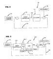
- FIG. 5 is an alternate embodiment of a control system incorporating a weight or constraint for a second actuator or microactuator for a dual stage actuator assembly.
- FIG. 6 is an alternate embodiment of a control system incorporating weights or constraints.
- FIG. 7 schematically illustrates uncertainty models for a primary actuator or voice coil motor (VCM) and a secondary actuator or microactuator.
- VCM voice coil motor
- FIGS. 8 - 9 illustrate frequency response models for the first actuator or voice coil motor and second actuator or microactuator, respectively including model uncertainty envelopes.
- FIG. 10 graphically illustrates control weights or constraints for different control designs for the second actuator or microactuator.
- FIGS. 11 - 12 graphically illustrate frequency response for desired servo performance transfer functions that result from constraints or weights illustrated in FIG. 6.
- FIG. 13 graphically illustrates sensitivity response for modeled control constraints as illustrated in FIGS. 6 , 8 - 9 and 10 - 12 .
- FIG. 14 graphically illustrates a ratio of the response for the control constraints illustrated in FIG. 13.
- FIG. 15 graphically illustrates relative contribution to disturbance rejection for the control constraints illustrated in FIGS. 6 , 8 - 9 and 10 - 12 .
- FIG. 16 graphically illustrates a ratio for stroke reduction for the control constraints illustrated in FIG. 15.
- FIG. 17 graphically illustrates non repeatable run out (NRRO) for the control constraints illustrated in FIGS. 6 , 8 - 9 and 10 - 12 .
- NRRO non repeatable run out
- FIG. 18 graphically illustrates a ratio of NRRO for the control constraints illustrated in FIG. 17.
- FIG. 19 graphically illustrates required stroke for different rotational vibration levels for the control constraints illustrated in FIGS. 6 , 8 - 9 and 10 - 12 .
- FIG. 20 graphically illustrates a ratio of the stroke for different rotational vibration levels for the control constraints illustrated in FIG. 19.
- FIG. 1 is a perspective illustration of an embodiment of a data storage device 100 for storing digital information.
- Device 100 includes a plurality of discs 102 (or single disc) to store digital information.
- the discs 102 are supported for rotation as illustrated by arrow 104 relative to a base chassis 106 by a spindle motor (not shown).
- Heads 108 (only one shown in FIG. 1) are coupled to an actuator assembly 110 including a voice coil motor or actuator 112 which is energized to position the heads 108 relative to data tracks on the disc to read data from or write data to the disc through interface with a host system 114 .
- Microactuators as illustrated in block 116 are coupled to the head to provide a smaller actuation stroke for fine head positioning control relative to the voice coil motor or primary actuator 112 .
- heads 108 are supported relative to an actuator E-block 120 rotationally coupled to the base chassis 106 .
- Energization of the voice coil motor 112 rotates the actuator E-block 120 to move the heads along a positioning stroke or arcuate path 122 between an inner diameter and outer diameter of the disc.
- Heads are coupled to suspension assemblies 124 (only one shown in FIG. 1) coupled to actuator arms 126 (only one shown in FIG. 1) of the actuator E-block 120 .
- microactuators 116 are coupled to suspension assemblies 124 to move the head 108 along a micro positioning stroke or smaller stroke than the primary actuator or voice coil motor 112 to provide fine head positioning along a relative small stroke.
- Microactuator 116 can be a piezoelectric microactuator, an electrostatic microactuator, an electromagnetic microactuator, or a shape memory actuator. Although a particular microactuator 116 is described and illustrated, application of the present invention is not limited to any particular microactuator structure or embodiment.
- operation of the actuator or voice coil motor 112 is controlled by a servo control system 130 using embedded servo positioning information.
- a servo controller 132 receives a seek or input command from the host system as illustrated by block 134 .
- the servo controller 132 provides a current or input signal 136 to the actuator 112 to energize the actuator to move the head 108 to a target position or data track.
- the control system 130 provides position feedback to the controller 132 of the actual position of the head 108 in response to displacement of the actuator 112 and system disturbances 140 .
- the present invention provides a control system for an actuator assembly with multiple or dual stage actuators some of which have less displacement capability than others, an embodiment of which is illustrated in FIG. 3 where like numbers are used to refer to like parts in the previous figures.
- the controller 132 - 1 receives an input or seek command 134 and provides a signal or current 136 - 1 to energize the primary actuator or voice coil motor 112 and a signal 136 - 2 to energize the microactuator 116 to position the head 108 for read/write operations.
- signals 136 - 1 , 136 - 2 energize actuators 112 , 116 to collectively move the head 108 to the desired position.
- the control system includes a feedback loop 138 to provide position feedback to control the position of the head 108 in response to movement of the actuators 112 , 116 and system disturbances 140 based upon servo position data.
- a feedback loop 138 to provide position feedback to control the position of the head 108 in response to movement of the actuators 112 , 116 and system disturbances 140 based upon servo position data.
- application of the present invention is not limited to the specific system illustrated in FIG. 3 and the present invention can be applied to any dual stage servo system including a master/slave interconnect for the actuators 112 , 116 .
- a position feedback 138 is shown, the present invention relates to any feedback architecture containing two or more actuators and one or more feedback signals.
- FIG. 4 illustrates an embodiment of a control system 130 - 2 of the present invention.
- the control system 130 - 2 includes a control weight or constraint 142 to control performance response or minimize stroke utilization of the secondary actuator or microactuator 116 .
- the weight or constraint 142 limits or reduces microactuator stroke utilization as illustrated by block 143 so that the control system does not exceed performance parameters or physical limitations of the microactuator or secondary actuator 116 .
- the weight or constraint 142 consists of a frequency based filter that constrains the frequency content of the control signal 136 - 2 of the microactuator 116 as will be described.
- the microactuator control weight or constraint 142 - 3 is at the output of the microactuator 116 rather than at the input as illustrated in FIG. 4 and application is not limited to the specific embodiments shown, as previously described.
- FIG. 6 illustrates an alternate embodiment of a control system 130 - 3 including a control constraint or weight 142 for the microactuator 116 and a control constraint or weight 144 for the primary actuator or VCM 112 to control stoke utilization as illustrated by block 145 to facilitate improved transition between the primary actuator and the secondary actuator or microactuator 116 .
- FIG. 6 illustrates a constraint weight 142 , 144 for both the microactuator 116 and the primary actuator or VCM 112
- application is not limited to a constraint for both the primary actuator 112 and secondary actuator or microactuator 116 and the system can include a constraint for the primary actuator 112 or secondary actuator 116 or both.
- the control system includes at least one servo performance or control loop constraint such as 146 - 1 , 146 - 2 .
- the control assembly includes servo performance constraints 146 - 1 , 146 - 2 for system disturbances W d 148 and displacement W p 149 , respectively, to control closed loop response of the servo loop or bandwidth.
- additional constraints for example input disturbances to the VCM or primary actuator in block 112 , can be accommodated by the methods described herein, and application of the present invention is not limited to a particular servo constraint.
- the constraints or weights 142 , 144 or 146 are mathematical constraints which are mathematically determined.
- the constraints are mathematically derived using an iterative process to synthesize controller 132 .
- the constraints are determined from a control synthesis block 150 as illustrated in FIGS. 4 - 6 to optimize the control system using uncertainty models 112 - 1 , 116 - 1 for the actuators 112 , 116 including an uncertainty mathematical model with structured uncertainty operator Delta A as illustrated in FIG. 7.
- the control synthesis block 150 uses the uncertainty models 112 - 1 , 116 - 1 for the voice coil motor and microactuator as illustrated in 152 , 154 of FIGS. 8 - 9 to minimize utilized stroke and/or optimize control servo closed loop response.
- the uncertainty models as illustrated in FIGS. 8 - 9 provide a model uncertainty envelope for a frequency domain range to accommodate for design or dynamic variations of the actuators 112 , 116 .
- the model envelope consists of envelopes in the operating frequency domain of the system.
- the control synthesis block 150 uses a control synthesis or loop-shaping program such as that available from MathWorks Inc. of Natick, Mass. (www.MathWorks.com) to optimize performance response for the system constraints using an iterative process based upon the uncertainty models 112 - 1 , 116 - 1 for the voice coil motor and microactuator, respectively.
- FIG. 10 illustrates frequency response plots for modeling different control weights or constraints 142 - 1 , 142 - 2 for the microactuator to synthesize controller 132 - 1 .
- Control weight or constraints 142 - 1 , 142 - 2 are frequency domain constraints and first constraint 142 - 1 is for a first control design and second constraint or weight 142 - 2 is for a second control design.
- performance characteristics for different constraints or weights 142 - 1 , 142 - 2 as illustrated in FIG. 10 are modeled iteratively for system optimization using the uncertainty models for the actuators 112 , 116 .
- control weight 142 - 1 allows greater microactuator motion for a frequency range below approximately 1000 Hz while control weight 142 - 2 allows less microactuator motion below approximately 1000 Hz.
- FIGS. 11 - 12 illustrate frequency response plots for modeling servo performance constraint or weights 146 - 1 , 146 - 2 for sensitivity and open loop gain, respectively, to control response of the servo system and magnitude and frequency of the disturbance components.
- FIG. 13 illustrates a synthesized sensitivity frequency response 160 corresponding to microactuator control constraints 142 - 1 , 142 - 2 , performance weight 146 - 1 , 146 - 2 and uncertainty models 112 - 1 , 116 - 1 and
- FIG. 14 illustrates a ratio in the frequency domain of sensitivity response 162 corresponding to constraint or design 142 - 2 versus constraint 142 - 1 .
- design 142 - 2 has less than 1 db worse performance than constraint or design 142 - 1 .
- FIG. 15 illustrates a comparison of utilization of the voice coil motor and microactuator for constraints 142 - 1 , 142 - 2 .
- constraint 142 - 2 utilizes significantly less stroke compared to constraint 142 - 1 below 1000 Hz.
- Line 170 in FIG. 16 represents a ratio of microactuation stroke utilization for constraint 142 - 2 relative to constraint 142 - 1 .
- constraint 142 - 1 requires as much as 25 db more microactuator stroke than control design 142 - 2 .
- FIGS. 17 - 18 illustrate performance for control systems synthesized with the two constraints or weights 142 - 1 , 142 - 2 in a drive or device under rotational vibration or RV excitation.
- FIG. 17 illustrates non repeatable run-out (NRRO) for constraints 142 - 1 , 142 - 2 and line 172 in FIG. 18 illustrates a ratio of NRRO for constraint 142 - 2 relative to constraint 142 - 1 .
- NRRO non repeatable run-out
- line 172 in FIG. 18 illustrates a ratio of NRRO for constraint 142 - 2 relative to constraint 142 - 1 .
- constraint 142 - 1 enters stroke saturation at approximately 50 rad/sec 2 and requires anti-windup to preserve stability.
- FIG. 17 illustrates non repeatable run-out
- the control design for constraint 142 - 2 is less than 1.3 db (16%) worse than the control design for constraint 142 - 1 up to 50 rad/sec 2 disturbance. Above 50 rad/sec 2 , constraint 142 - 2 is significantly better than constraint 142 - 1 since the control design using constraint 142 - 1 enters stroke saturation whereas the control design using constraint 142 - 2 never enters saturation.
- FIGS. 19 - 20 illustrate stroke comparisons for constraints or weights 142 - 1 , 142 - 2 at different excitation levels.
- constraint 142 - 1 enters stroke saturation at approximately 50 rad/sec 2 and requires anti-windup to preserve stability.
- the control design using constraint 142 - 1 requires 12 db (4 times) more stroke than the control design using constraint 142 - 2 at 21 rad/sec 2 which corresponds to the typical operational RV requirements for enterprise class disc drives. This reduction in stroke was obtained with less than a 12% increase in NRRO (or 1.3% track pitch) and as described constraint 142 - 2 provides optimum system performance relative to constraint 142 - 1 for head positioning control.
- a control system (such as 130 - 1 , 130 - 2 , 130 - 3 ) for a data storage device is disclosed which includes a control constraint or weight (such as 142 , 144 , 146 ).
- the constraint or weight (such as 142 , 144 , 146 ) is a frequency based constraint and is used to control performance of one or more actuators.
- the weight or constraint (such as 142 ) is used to limit stroke utilization for a microactuator (such as 116 ) having a smaller stroke than a primary actuator.
- a controller for a control system is synthesized using uncertain actuator models (such as 152 , 154 ) and actuator utilization constraints (such as 142 ) or other constraints to optimize system performance and in a particular embodiment to minimize stroke utilized by the microactuator (such as 116 ) without compromising system performance.
Landscapes
- Moving Of The Head To Find And Align With The Track (AREA)
Abstract
Description
- This application claims priority from U.S. Provisional Application No. 60/374,081 filed on Apr. 18, 2002 entitled “MINIMIZING REQUIRED STROKE OF MICROACTUATOR FOR DUAL-STAGE DISC DRIVE”.
- The present invention relates generally to data storage devices, and more particularly but not by limitation to control systems for data storage devices.
- Data storage devices store digital information on a rotating disc or data storage medium. Data storage devices include a head having a transducer element to read data from or write data to the disc or data storage medium. Heads are coupled to a primary or first actuator assembly which is energized to position the head relative to the disc surface for read-write operations. The primary actuator is coupled to a servo control system to provide head position control. Areal density is increasing requiring improved position control. In particular, as tracks per inch increase, track positioning error must decrease.
- Secondary actuators or microactuators have been proposed to improve track misregistration or track positioning. Typically, the secondary actuator or microactuator moves the head over a smaller stroke or displacement to provide micropositioning for dual stage actuation. The primary, or first actuator, and the secondary actuator, or microactuator, collectively provide head positioning. Control system architectures for single actuation devices are not designed to optimize servo control for the secondary actuator or microactuator relative to system constraints. Embodiments of the present invention provide solutions to these and other problems, and offer other advantages over the prior art.
- The present invention relates to a control system for a data storage device including a constraint or weight to control stroke utilization and/or closed loop response of the control system. In particular, in one embodiment described, the weight or constraint is used to limit stroke utilization for a microactuator having a smaller stroke than a primary actuator. As described, the constraint or weight is used in conjunction with mathematical synthesis to synthesize a controller to optimize system performance. These and other features and benefits that characterize embodiments of the present invention will be apparent upon reading the following detailed description and review of the associated drawings.
- FIG. 1 is a perspective illustration of an embodiment of a data storage device.
- FIG. 2 is a schematic illustration of an embodiment of a control system for an actuator to position a head for read-write operations.
- FIG. 3 is a schematic illustration of an embodiment of a control system for a dual stage actuator assembly of the present invention.
- FIG. 4 is a schematic illustration of an embodiment of a control system incorporating a weight or constraint for a second actuator or microactuator for a dual stage actuator assembly.
- FIG. 5 is an alternate embodiment of a control system incorporating a weight or constraint for a second actuator or microactuator for a dual stage actuator assembly.
- FIG. 6 is an alternate embodiment of a control system incorporating weights or constraints.
- FIG. 7 schematically illustrates uncertainty models for a primary actuator or voice coil motor (VCM) and a secondary actuator or microactuator.
- FIGS. 8-9 illustrate frequency response models for the first actuator or voice coil motor and second actuator or microactuator, respectively including model uncertainty envelopes.
- FIG. 10 graphically illustrates control weights or constraints for different control designs for the second actuator or microactuator.
- FIGS. 11-12 graphically illustrate frequency response for desired servo performance transfer functions that result from constraints or weights illustrated in FIG. 6.
- FIG. 13 graphically illustrates sensitivity response for modeled control constraints as illustrated in FIGS. 6, 8-9 and 10-12.
- FIG. 14 graphically illustrates a ratio of the response for the control constraints illustrated in FIG. 13.
- FIG. 15 graphically illustrates relative contribution to disturbance rejection for the control constraints illustrated in FIGS. 6, 8-9 and 10-12.
- FIG. 16 graphically illustrates a ratio for stroke reduction for the control constraints illustrated in FIG. 15.
- FIG. 17 graphically illustrates non repeatable run out (NRRO) for the control constraints illustrated in FIGS. 6, 8-9 and 10-12.
- FIG. 18 graphically illustrates a ratio of NRRO for the control constraints illustrated in FIG. 17.
- FIG. 19 graphically illustrates required stroke for different rotational vibration levels for the control constraints illustrated in FIGS. 6, 8-9 and 10-12.
- FIG. 20 graphically illustrates a ratio of the stroke for different rotational vibration levels for the control constraints illustrated in FIG. 19.
- FIG. 1 is a perspective illustration of an embodiment of a
data storage device 100 for storing digital information.Device 100 includes a plurality of discs 102 (or single disc) to store digital information. Thediscs 102 are supported for rotation as illustrated byarrow 104 relative to abase chassis 106 by a spindle motor (not shown). Heads 108 (only one shown in FIG. 1) are coupled to anactuator assembly 110 including a voice coil motor oractuator 112 which is energized to position theheads 108 relative to data tracks on the disc to read data from or write data to the disc through interface with ahost system 114. - As previously described, areal density and tracks per inch is increasing, demanding improved head positioning control. The size and response of the
actuator 112 limits response or positioning control of thehead 108. Microactuators as illustrated inblock 116 are coupled to the head to provide a smaller actuation stroke for fine head positioning control relative to the voice coil motor orprimary actuator 112. - In particular, in the illustrated embodiment,
heads 108 are supported relative to anactuator E-block 120 rotationally coupled to thebase chassis 106. Energization of thevoice coil motor 112 rotates theactuator E-block 120 to move the heads along a positioning stroke orarcuate path 122 between an inner diameter and outer diameter of the disc. Heads are coupled to suspension assemblies 124 (only one shown in FIG. 1) coupled to actuator arms 126 (only one shown in FIG. 1) of theactuator E-block 120. - In the illustrated embodiment,
microactuators 116 are coupled tosuspension assemblies 124 to move thehead 108 along a micro positioning stroke or smaller stroke than the primary actuator orvoice coil motor 112 to provide fine head positioning along a relative small stroke.Microactuator 116 can be a piezoelectric microactuator, an electrostatic microactuator, an electromagnetic microactuator, or a shape memory actuator. Although aparticular microactuator 116 is described and illustrated, application of the present invention is not limited to any particular microactuator structure or embodiment. - As shown in FIG. 2, operation of the actuator or
voice coil motor 112 is controlled by aservo control system 130 using embedded servo positioning information. As shown in FIG. 2, aservo controller 132 receives a seek or input command from the host system as illustrated byblock 134. Theservo controller 132 provides a current orinput signal 136 to theactuator 112 to energize the actuator to move thehead 108 to a target position or data track. As illustrated byline 138, thecontrol system 130 provides position feedback to thecontroller 132 of the actual position of thehead 108 in response to displacement of theactuator 112 andsystem disturbances 140. Feedback of the actual position of thehead 108 relative to the target position of the head is used to provide a position error signal to energize or control theactuator 112 for desired head placement. As previously discussed, to improve head positioning control, a secondary actuator or microactuator is included to provide dual stage actuation. The present invention provides a control system for an actuator assembly with multiple or dual stage actuators some of which have less displacement capability than others, an embodiment of which is illustrated in FIG. 3 where like numbers are used to refer to like parts in the previous figures. As shown, the controller 132-1 receives an input or seekcommand 134 and provides a signal or current 136-1 to energize the primary actuator orvoice coil motor 112 and a signal 136-2 to energize themicroactuator 116 to position thehead 108 for read/write operations. As shown, signals 136-1, 136-2energize actuators head 108 to the desired position. - As previously described, the control system includes a
feedback loop 138 to provide position feedback to control the position of thehead 108 in response to movement of theactuators system disturbances 140 based upon servo position data. Although a particular control system is illustrated, application of the present invention is not limited to the specific system illustrated in FIG. 3 and the present invention can be applied to any dual stage servo system including a master/slave interconnect for theactuators position feedback 138 is shown, the present invention relates to any feedback architecture containing two or more actuators and one or more feedback signals. - FIG. 4 illustrates an embodiment of a control system 130-2 of the present invention. As illustrated the control system 130-2 includes a control weight or
constraint 142 to control performance response or minimize stroke utilization of the secondary actuator ormicroactuator 116. The weight orconstraint 142 limits or reduces microactuator stroke utilization as illustrated byblock 143 so that the control system does not exceed performance parameters or physical limitations of the microactuator orsecondary actuator 116. - In a preferred embodiment, the weight or
constraint 142 consists of a frequency based filter that constrains the frequency content of the control signal 136-2 of themicroactuator 116 as will be described. In an alternative embodiment illustrated in FIG. 5, the microactuator control weight or constraint 142-3 is at the output of themicroactuator 116 rather than at the input as illustrated in FIG. 4 and application is not limited to the specific embodiments shown, as previously described. - FIG. 6 illustrates an alternate embodiment of a control system 130-3 including a control constraint or
weight 142 for themicroactuator 116 and a control constraint orweight 144 for the primary actuator orVCM 112 to control stoke utilization as illustrated byblock 145 to facilitate improved transition between the primary actuator and the secondary actuator ormicroactuator 116. Although, FIG. 6 illustrates aconstraint weight microactuator 116 and the primary actuator orVCM 112, application is not limited to a constraint for both theprimary actuator 112 and secondary actuator ormicroactuator 116 and the system can include a constraint for theprimary actuator 112 orsecondary actuator 116 or both. - Also in the embodiment shown in FIG. 6, the control system includes at least one servo performance or control loop constraint such as 146-1, 146-2. In a particular or preferred embodiment shown, the control assembly includes servo performance constraints 146-1, 146-2 for
system disturbances W d 148 anddisplacement W p 149, respectively, to control closed loop response of the servo loop or bandwidth. As will be appreciated by those skilled in the art, additional constraints, for example input disturbances to the VCM or primary actuator inblock 112, can be accommodated by the methods described herein, and application of the present invention is not limited to a particular servo constraint. - The constraints or
weights controller 132. In particular, the constraints are determined from acontrol synthesis block 150 as illustrated in FIGS. 4-6 to optimize the control system using uncertainty models 112-1, 116-1 for theactuators control synthesis block 150 uses the uncertainty models 112-1, 116-1 for the voice coil motor and microactuator as illustrated in 152, 154 of FIGS. 8-9 to minimize utilized stroke and/or optimize control servo closed loop response. - The uncertainty models as illustrated in FIGS. 8-9 provide a model uncertainty envelope for a frequency domain range to accommodate for design or dynamic variations of the
actuators control synthesis block 150 uses a control synthesis or loop-shaping program such as that available from MathWorks Inc. of Natick, Mass. (www.MathWorks.com) to optimize performance response for the system constraints using an iterative process based upon the uncertainty models 112-1, 116-1 for the voice coil motor and microactuator, respectively. - FIG. 10 illustrates frequency response plots for modeling different control weights or constraints 142-1, 142-2 for the microactuator to synthesize controller 132-1. Control weight or constraints 142-1, 142-2 are frequency domain constraints and first constraint 142-1 is for a first control design and second constraint or weight 142-2 is for a second control design. As previously described, performance characteristics for different constraints or weights 142-1, 142-2 as illustrated in FIG. 10 are modeled iteratively for system optimization using the uncertainty models for the
actuators - FIGS. 11-12 illustrate frequency response plots for modeling servo performance constraint or weights 146-1, 146-2 for sensitivity and open loop gain, respectively, to control response of the servo system and magnitude and frequency of the disturbance components. In particular FIG. 11 illustrates an inverse weight or constraint=(WdWp)−1 for the frequency domain.
- FIG. 13 illustrates a synthesized
sensitivity frequency response 160 corresponding to microactuator control constraints 142-1, 142-2, performance weight 146-1, 146-2 and uncertainty models 112-1, 116-1 and FIG. 14 illustrates a ratio in the frequency domain ofsensitivity response 162 corresponding to constraint or design 142-2 versus constraint 142-1. As illustrated at a low frequency range (<approximately 1000 Hz), design 142-2 has less than 1 db worse performance than constraint or design 142-1. - FIG. 15 illustrates a comparison of utilization of the voice coil motor and microactuator for constraints 142-1, 142-2. As shown, constraint 142-2 utilizes significantly less stroke compared to constraint 142-1 below 1000 Hz.
Line 170 in FIG. 16 represents a ratio of microactuation stroke utilization for constraint 142-2 relative to constraint 142-1. As illustrated, constraint 142-1 requires as much as 25 db more microactuator stroke than control design 142-2. - FIGS. 17-18 illustrate performance for control systems synthesized with the two constraints or weights 142-1, 142-2 in a drive or device under rotational vibration or RV excitation. FIG. 17 illustrates non repeatable run-out (NRRO) for constraints 142-1, 142-2 and
line 172 in FIG. 18 illustrates a ratio of NRRO for constraint 142-2 relative to constraint 142-1. As shown in FIG. 17, constraint 142-1 enters stroke saturation at approximately 50 rad/sec2 and requires anti-windup to preserve stability. As illustrated in FIG. 18, the control design for constraint 142-2 is less than 1.3 db (16%) worse than the control design for constraint 142-1 up to 50 rad/sec2 disturbance. Above 50 rad/sec2, constraint 142-2 is significantly better than constraint 142-1 since the control design using constraint 142-1 enters stroke saturation whereas the control design using constraint 142-2 never enters saturation. - FIGS. 19-20 illustrate stroke comparisons for constraints or weights 142-1, 142-2 at different excitation levels. As shown, constraint 142-1 enters stroke saturation at approximately 50 rad/sec2 and requires anti-windup to preserve stability. As shown by the
ratio 180 in FIG. 20, the control design using constraint 142-1 requires 12 db (4 times) more stroke than the control design using constraint 142-2 at 21 rad/sec2 which corresponds to the typical operational RV requirements for enterprise class disc drives. This reduction in stroke was obtained with less than a 12% increase in NRRO (or 1.3% track pitch) and as described constraint 142-2 provides optimum system performance relative to constraint 142-1 for head positioning control. - A control system (such as 130-1, 130-2, 130-3) for a data storage device is disclosed which includes a control constraint or weight (such as 142, 144, 146). In illustrated embodiments, the constraint or weight (such as 142, 144, 146) is a frequency based constraint and is used to control performance of one or more actuators. In particular, in the embodiments described, the weight or constraint (such as 142) is used to limit stroke utilization for a microactuator (such as 116) having a smaller stroke than a primary actuator. As described, a controller for a control system is synthesized using uncertain actuator models (such as 152, 154) and actuator utilization constraints (such as 142) or other constraints to optimize system performance and in a particular embodiment to minimize stroke utilized by the microactuator (such as 116) without compromising system performance.
- It is to be understood that even though numerous characteristics and advantages of various embodiments of the invention have been set forth in the foregoing description, together with details of the structure and function of various embodiments of the invention, this disclosure is illustrative only, and changes may be made in detail, especially in matters of structure and arrangement of parts within the principles of the present invention to the full extent indicated by the broad general meaning of the terms in which the appended claims are expressed. For example, the particular elements may vary depending on the particular application while maintaining substantially the same functionality without departing from the scope and spirit of the present invention. In addition, although the preferred embodiment described herein is directed to a particular control system for particular application, it will be appreciated by those skilled in the art that the teachings of the present invention can be applied to other systems, without departing from the scope and spirit of the present invention.
Claims (25)
Priority Applications (1)
| Application Number | Priority Date | Filing Date | Title |
|---|---|---|---|
| US10/353,602 US7038876B2 (en) | 2002-04-18 | 2003-01-29 | Control system for a data storage device with constraint |
Applications Claiming Priority (2)
| Application Number | Priority Date | Filing Date | Title |
|---|---|---|---|
| US37408102P | 2002-04-18 | 2002-04-18 | |
| US10/353,602 US7038876B2 (en) | 2002-04-18 | 2003-01-29 | Control system for a data storage device with constraint |
Publications (2)
| Publication Number | Publication Date |
|---|---|
| US20030197972A1 true US20030197972A1 (en) | 2003-10-23 |
| US7038876B2 US7038876B2 (en) | 2006-05-02 |
Family
ID=29251132
Family Applications (1)
| Application Number | Title | Priority Date | Filing Date |
|---|---|---|---|
| US10/353,602 Expired - Fee Related US7038876B2 (en) | 2002-04-18 | 2003-01-29 | Control system for a data storage device with constraint |
Country Status (3)
| Country | Link |
|---|---|
| US (1) | US7038876B2 (en) |
| AU (1) | AU2003210697A1 (en) |
| WO (1) | WO2003090212A1 (en) |
Cited By (3)
| Publication number | Priority date | Publication date | Assignee | Title |
|---|---|---|---|---|
| US6975482B1 (en) * | 2003-03-06 | 2005-12-13 | Maxtor Corporation | Settle control systems and methods for the second stage of a dual stage actuator |
| WO2010051171A1 (en) * | 2008-10-27 | 2010-05-06 | Schlumberger Canada Limited | Process and apparatus for processing signals |
| US8886467B2 (en) | 2008-10-27 | 2014-11-11 | Schlumberger Technology Corporation | Process and apparatus for processing signals |
Families Citing this family (7)
| Publication number | Priority date | Publication date | Assignee | Title |
|---|---|---|---|---|
| WO2006058000A1 (en) | 2004-11-24 | 2006-06-01 | Shell Internationale Research Maatschappij B.V. | Separator for multi-phase slug flow and method of designing same |
| JP4783248B2 (en) | 2006-09-12 | 2011-09-28 | 東芝ストレージデバイス株式会社 | POSITION CONTROL METHOD, POSITION CONTROL DEVICE, AND MEDIUM STORAGE DEVICE WITH DISTURBANCE SUPPRESSING FUNCTION |
| US8553368B2 (en) | 2007-11-19 | 2013-10-08 | HGST Netherlands B.V. | High aspect ratio motion limiter of a microactuator and method for fabrication |
| US7595956B2 (en) * | 2007-12-31 | 2009-09-29 | Hitachi Global Storage Technologies Netherlands B.V. | Microactuator reference input limit to prevent internal states over-accumulation |
| US9025273B1 (en) | 2013-08-28 | 2015-05-05 | Western Digital Technologies, Inc. | Disk drive employing digital accumulators to limit velocity and/or acceleration of microactuator |
| US9142225B1 (en) | 2014-03-21 | 2015-09-22 | Western Digital Technologies, Inc. | Electronic system with actuator control mechanism and method of operation thereof |
| US9007714B1 (en) | 2014-07-18 | 2015-04-14 | Western Digital Technologies Inc. | Data storage device comprising slew rate anti-windup compensation for microactuator |
Citations (11)
| Publication number | Priority date | Publication date | Assignee | Title |
|---|---|---|---|---|
| US5978752A (en) * | 1997-08-07 | 1999-11-02 | Seagate Technology, Inc. | Model validation algorithm for characterizing parameters and uncertainty in a disc drive |
| US6005742A (en) * | 1995-09-22 | 1999-12-21 | International Business Machines Corporation | Method and apparatus for controlling a multiple-stage actuator for a disk drive |
| US6101058A (en) * | 1997-08-07 | 2000-08-08 | Seagate Technology, Inc. | Method of implementing a linear discrete-time state-space servo control system on a fixed-point digital signal processor in a disc drive |
| US6166890A (en) * | 1998-07-24 | 2000-12-26 | Seagate Technology Llc | In plane, push-pull parallel force microactuator |
| US6266205B1 (en) * | 1998-03-10 | 2001-07-24 | Maxtor Corporation | Parallel servo with ultra high bandwidth off-track detection |
| US6519109B1 (en) * | 2000-07-21 | 2003-02-11 | International Business Machines Corporation | Method and apparatus for providing feedforward control of two interacting actuators |
| US6600622B1 (en) * | 2000-02-11 | 2003-07-29 | Hitachi Global Storage Technologies Netherlands B.V. | System and method for detecting displacement of disk drive heads on micro actuators due to contact with disks |
| US6618221B2 (en) * | 2001-05-07 | 2003-09-09 | International Business Machines Corporation | System and method for utilizing an actuator-activated pumping mechanism for reducing the operating pressure of a disk drive assembly |
| US6621653B1 (en) * | 2000-06-09 | 2003-09-16 | Hitachi Global Storage Technologies Netherlands B.V. | Secondary actuator system for mode compensation |
| US6700736B1 (en) * | 2002-03-29 | 2004-03-02 | Western Digital Technologies, Inc. | Airflow spoiler between co-rotating disks |
| US6738229B2 (en) * | 2000-12-29 | 2004-05-18 | Maxtor Corporation | Head stack assembly having decreased track misregistration characteristics |
Family Cites Families (2)
| Publication number | Priority date | Publication date | Assignee | Title |
|---|---|---|---|---|
| GB2366658B (en) * | 1999-06-24 | 2003-11-05 | Seagate Technology Llc | Method and apparatus for maintaining servo stability during actuator saturation |
| SG106039A1 (en) * | 2000-01-11 | 2004-09-30 | Univ Singapore | Robust triple-mode compensator for hard disk drives with dynamic friction |
-
2003
- 2003-01-29 AU AU2003210697A patent/AU2003210697A1/en not_active Abandoned
- 2003-01-29 US US10/353,602 patent/US7038876B2/en not_active Expired - Fee Related
- 2003-01-29 WO PCT/US2003/002521 patent/WO2003090212A1/en not_active Ceased
Patent Citations (11)
| Publication number | Priority date | Publication date | Assignee | Title |
|---|---|---|---|---|
| US6005742A (en) * | 1995-09-22 | 1999-12-21 | International Business Machines Corporation | Method and apparatus for controlling a multiple-stage actuator for a disk drive |
| US5978752A (en) * | 1997-08-07 | 1999-11-02 | Seagate Technology, Inc. | Model validation algorithm for characterizing parameters and uncertainty in a disc drive |
| US6101058A (en) * | 1997-08-07 | 2000-08-08 | Seagate Technology, Inc. | Method of implementing a linear discrete-time state-space servo control system on a fixed-point digital signal processor in a disc drive |
| US6266205B1 (en) * | 1998-03-10 | 2001-07-24 | Maxtor Corporation | Parallel servo with ultra high bandwidth off-track detection |
| US6166890A (en) * | 1998-07-24 | 2000-12-26 | Seagate Technology Llc | In plane, push-pull parallel force microactuator |
| US6600622B1 (en) * | 2000-02-11 | 2003-07-29 | Hitachi Global Storage Technologies Netherlands B.V. | System and method for detecting displacement of disk drive heads on micro actuators due to contact with disks |
| US6621653B1 (en) * | 2000-06-09 | 2003-09-16 | Hitachi Global Storage Technologies Netherlands B.V. | Secondary actuator system for mode compensation |
| US6519109B1 (en) * | 2000-07-21 | 2003-02-11 | International Business Machines Corporation | Method and apparatus for providing feedforward control of two interacting actuators |
| US6738229B2 (en) * | 2000-12-29 | 2004-05-18 | Maxtor Corporation | Head stack assembly having decreased track misregistration characteristics |
| US6618221B2 (en) * | 2001-05-07 | 2003-09-09 | International Business Machines Corporation | System and method for utilizing an actuator-activated pumping mechanism for reducing the operating pressure of a disk drive assembly |
| US6700736B1 (en) * | 2002-03-29 | 2004-03-02 | Western Digital Technologies, Inc. | Airflow spoiler between co-rotating disks |
Cited By (4)
| Publication number | Priority date | Publication date | Assignee | Title |
|---|---|---|---|---|
| US6975482B1 (en) * | 2003-03-06 | 2005-12-13 | Maxtor Corporation | Settle control systems and methods for the second stage of a dual stage actuator |
| WO2010051171A1 (en) * | 2008-10-27 | 2010-05-06 | Schlumberger Canada Limited | Process and apparatus for processing signals |
| US8649984B2 (en) | 2008-10-27 | 2014-02-11 | Schlumberger Technology Corporation | Process and apparatus for processing signals |
| US8886467B2 (en) | 2008-10-27 | 2014-11-11 | Schlumberger Technology Corporation | Process and apparatus for processing signals |
Also Published As
| Publication number | Publication date |
|---|---|
| US7038876B2 (en) | 2006-05-02 |
| WO2003090212A1 (en) | 2003-10-30 |
| AU2003210697A1 (en) | 2003-11-03 |
Similar Documents
| Publication | Publication Date | Title |
|---|---|---|
| US6710966B1 (en) | Method for reducing an effect of vibration on a disk drive during a track following operation by adjusting an adaptive-filter gain applied to an acceleration sensor signal | |
| US5978752A (en) | Model validation algorithm for characterizing parameters and uncertainty in a disc drive | |
| US6522494B1 (en) | Apparatus and method for writing servo patterns on a computer hard disk | |
| US5991114A (en) | Disc drive having gram load reducer and method of operating gram load reducer | |
| US6519109B1 (en) | Method and apparatus for providing feedforward control of two interacting actuators | |
| US6768610B1 (en) | Microactuator servo system in a disc drive | |
| CN101882444A (en) | Correction of hard drive write head positioning errors | |
| WO1999044194A1 (en) | Minimizing settling time in a disc drive servo system | |
| US7038876B2 (en) | Control system for a data storage device with constraint | |
| US6721124B2 (en) | Method and apparatus for providing an intelligent settle scheme for a hard disk drive with dual stage actuators | |
| US20230238024A1 (en) | Split actuator drive that limits slew rate of aggressor vcm to reduce victim disturbances | |
| US6594106B1 (en) | Adaptive servo estimator and compensator for coil and carriage deformation in voice coil motor driven hard disk drive | |
| KR100290604B1 (en) | Intelligent track pitch adjustment method for magnetic disk drive | |
| US6414827B1 (en) | Closed-loop scaling for discrete-time servo controller in a disc drive | |
| US6490120B1 (en) | Servo gain optimization using a variable convergence factor | |
| EP0969465A1 (en) | Apparatus for recording and reproducing information | |
| US6301080B1 (en) | Dither method to unload negative suction air bearings | |
| US6153998A (en) | Method of controlling a two-degree-of-freedom control system | |
| US6476998B2 (en) | Enhanced settling control in hard disk drive | |
| US9805750B1 (en) | Data storage loadbeam stiffening feature | |
| KR20010105409A (en) | Disc drive with actuator arm configured for reduced out-of-phase motion | |
| EP1422695B1 (en) | Head switching method using track number matching | |
| US6667845B1 (en) | Method and system for compensating for actuator resonances | |
| US20100079902A1 (en) | Controller and storage device | |
| US6538837B1 (en) | Method of aligning servo wedges in a disc drive |
Legal Events
| Date | Code | Title | Description |
|---|---|---|---|
| AS | Assignment |
Owner name: SEAGATE TECHNOLOGY LLC, CALIFORNIA Free format text: ASSIGNMENT OF ASSIGNORS INTEREST;ASSIGNOR:MORRIS, JOHN C.;REEL/FRAME:013722/0404 Effective date: 20030122 |
|
| FEPP | Fee payment procedure |
Free format text: PAYOR NUMBER ASSIGNED (ORIGINAL EVENT CODE: ASPN); ENTITY STATUS OF PATENT OWNER: LARGE ENTITY |
|
| AS | Assignment |
Owner name: WELLS FARGO BANK, NATIONAL ASSOCIATION, AS COLLATERAL AGENT AND SECOND PRIORITY REPRESENTATIVE, CALIFORNIA Free format text: SECURITY AGREEMENT;ASSIGNORS:MAXTOR CORPORATION;SEAGATE TECHNOLOGY LLC;SEAGATE TECHNOLOGY INTERNATIONAL;REEL/FRAME:022757/0017 Effective date: 20090507 Owner name: JPMORGAN CHASE BANK, N.A., AS ADMINISTRATIVE AGENT AND FIRST PRIORITY REPRESENTATIVE, NEW YORK Free format text: SECURITY AGREEMENT;ASSIGNORS:MAXTOR CORPORATION;SEAGATE TECHNOLOGY LLC;SEAGATE TECHNOLOGY INTERNATIONAL;REEL/FRAME:022757/0017 Effective date: 20090507 Owner name: JPMORGAN CHASE BANK, N.A., AS ADMINISTRATIVE AGENT Free format text: SECURITY AGREEMENT;ASSIGNORS:MAXTOR CORPORATION;SEAGATE TECHNOLOGY LLC;SEAGATE TECHNOLOGY INTERNATIONAL;REEL/FRAME:022757/0017 Effective date: 20090507 Owner name: WELLS FARGO BANK, NATIONAL ASSOCIATION, AS COLLATE Free format text: SECURITY AGREEMENT;ASSIGNORS:MAXTOR CORPORATION;SEAGATE TECHNOLOGY LLC;SEAGATE TECHNOLOGY INTERNATIONAL;REEL/FRAME:022757/0017 Effective date: 20090507 |
|
| FPAY | Fee payment |
Year of fee payment: 4 |
|
| AS | Assignment |
Owner name: MAXTOR CORPORATION, CALIFORNIA Free format text: RELEASE;ASSIGNOR:JPMORGAN CHASE BANK, N.A., AS ADMINISTRATIVE AGENT;REEL/FRAME:025662/0001 Effective date: 20110114 Owner name: SEAGATE TECHNOLOGY LLC, CALIFORNIA Free format text: RELEASE;ASSIGNOR:JPMORGAN CHASE BANK, N.A., AS ADMINISTRATIVE AGENT;REEL/FRAME:025662/0001 Effective date: 20110114 Owner name: SEAGATE TECHNOLOGY INTERNATIONAL, CALIFORNIA Free format text: RELEASE;ASSIGNOR:JPMORGAN CHASE BANK, N.A., AS ADMINISTRATIVE AGENT;REEL/FRAME:025662/0001 Effective date: 20110114 Owner name: SEAGATE TECHNOLOGY HDD HOLDINGS, CALIFORNIA Free format text: RELEASE;ASSIGNOR:JPMORGAN CHASE BANK, N.A., AS ADMINISTRATIVE AGENT;REEL/FRAME:025662/0001 Effective date: 20110114 |
|
| AS | Assignment |
Owner name: THE BANK OF NOVA SCOTIA, AS ADMINISTRATIVE AGENT, CANADA Free format text: SECURITY AGREEMENT;ASSIGNOR:SEAGATE TECHNOLOGY LLC;REEL/FRAME:026010/0350 Effective date: 20110118 Owner name: THE BANK OF NOVA SCOTIA, AS ADMINISTRATIVE AGENT, Free format text: SECURITY AGREEMENT;ASSIGNOR:SEAGATE TECHNOLOGY LLC;REEL/FRAME:026010/0350 Effective date: 20110118 |
|
| AS | Assignment |
Owner name: EVAULT INC. (F/K/A I365 INC.), CALIFORNIA Free format text: TERMINATION AND RELEASE OF SECURITY INTEREST IN PATENT RIGHTS;ASSIGNOR:WELLS FARGO BANK, NATIONAL ASSOCIATION, AS COLLATERAL AGENT AND SECOND PRIORITY REPRESENTATIVE;REEL/FRAME:030833/0001 Effective date: 20130312 Owner name: SEAGATE TECHNOLOGY LLC, CALIFORNIA Free format text: TERMINATION AND RELEASE OF SECURITY INTEREST IN PATENT RIGHTS;ASSIGNOR:WELLS FARGO BANK, NATIONAL ASSOCIATION, AS COLLATERAL AGENT AND SECOND PRIORITY REPRESENTATIVE;REEL/FRAME:030833/0001 Effective date: 20130312 Owner name: SEAGATE TECHNOLOGY INTERNATIONAL, CAYMAN ISLANDS Free format text: TERMINATION AND RELEASE OF SECURITY INTEREST IN PATENT RIGHTS;ASSIGNOR:WELLS FARGO BANK, NATIONAL ASSOCIATION, AS COLLATERAL AGENT AND SECOND PRIORITY REPRESENTATIVE;REEL/FRAME:030833/0001 Effective date: 20130312 Owner name: SEAGATE TECHNOLOGY US HOLDINGS, INC., CALIFORNIA Free format text: TERMINATION AND RELEASE OF SECURITY INTEREST IN PATENT RIGHTS;ASSIGNOR:WELLS FARGO BANK, NATIONAL ASSOCIATION, AS COLLATERAL AGENT AND SECOND PRIORITY REPRESENTATIVE;REEL/FRAME:030833/0001 Effective date: 20130312 |
|
| FPAY | Fee payment |
Year of fee payment: 8 |
|
| FEPP | Fee payment procedure |
Free format text: MAINTENANCE FEE REMINDER MAILED (ORIGINAL EVENT CODE: REM.) |
|
| LAPS | Lapse for failure to pay maintenance fees |
Free format text: PATENT EXPIRED FOR FAILURE TO PAY MAINTENANCE FEES (ORIGINAL EVENT CODE: EXP.) |
|
| STCH | Information on status: patent discontinuation |
Free format text: PATENT EXPIRED DUE TO NONPAYMENT OF MAINTENANCE FEES UNDER 37 CFR 1.362 |
|
| FP | Lapsed due to failure to pay maintenance fee |
Effective date: 20180502 |
|
| AS | Assignment |
Owner name: SEAGATE TECHNOLOGY PUBLIC LIMITED COMPANY, CALIFORNIA Free format text: RELEASE BY SECURED PARTY;ASSIGNOR:THE BANK OF NOVA SCOTIA;REEL/FRAME:072193/0001 Effective date: 20250303 Owner name: SEAGATE TECHNOLOGY, CALIFORNIA Free format text: RELEASE BY SECURED PARTY;ASSIGNOR:THE BANK OF NOVA SCOTIA;REEL/FRAME:072193/0001 Effective date: 20250303 Owner name: SEAGATE TECHNOLOGY HDD HOLDINGS, CALIFORNIA Free format text: RELEASE BY SECURED PARTY;ASSIGNOR:THE BANK OF NOVA SCOTIA;REEL/FRAME:072193/0001 Effective date: 20250303 Owner name: I365 INC., CALIFORNIA Free format text: RELEASE BY SECURED PARTY;ASSIGNOR:THE BANK OF NOVA SCOTIA;REEL/FRAME:072193/0001 Effective date: 20250303 Owner name: SEAGATE TECHNOLOGY LLC, CALIFORNIA Free format text: RELEASE BY SECURED PARTY;ASSIGNOR:THE BANK OF NOVA SCOTIA;REEL/FRAME:072193/0001 Effective date: 20250303 Owner name: SEAGATE TECHNOLOGY INTERNATIONAL, CAYMAN ISLANDS Free format text: RELEASE BY SECURED PARTY;ASSIGNOR:THE BANK OF NOVA SCOTIA;REEL/FRAME:072193/0001 Effective date: 20250303 Owner name: SEAGATE HDD CAYMAN, CAYMAN ISLANDS Free format text: RELEASE BY SECURED PARTY;ASSIGNOR:THE BANK OF NOVA SCOTIA;REEL/FRAME:072193/0001 Effective date: 20250303 Owner name: SEAGATE TECHNOLOGY (US) HOLDINGS, INC., CALIFORNIA Free format text: RELEASE BY SECURED PARTY;ASSIGNOR:THE BANK OF NOVA SCOTIA;REEL/FRAME:072193/0001 Effective date: 20250303 Owner name: SEAGATE TECHNOLOGY PUBLIC LIMITED COMPANY, CALIFORNIA Free format text: RELEASE OF SECURITY INTEREST;ASSIGNOR:THE BANK OF NOVA SCOTIA;REEL/FRAME:072193/0001 Effective date: 20250303 Owner name: SEAGATE TECHNOLOGY, CALIFORNIA Free format text: RELEASE OF SECURITY INTEREST;ASSIGNOR:THE BANK OF NOVA SCOTIA;REEL/FRAME:072193/0001 Effective date: 20250303 Owner name: SEAGATE TECHNOLOGY HDD HOLDINGS, CALIFORNIA Free format text: RELEASE OF SECURITY INTEREST;ASSIGNOR:THE BANK OF NOVA SCOTIA;REEL/FRAME:072193/0001 Effective date: 20250303 Owner name: I365 INC., CALIFORNIA Free format text: RELEASE OF SECURITY INTEREST;ASSIGNOR:THE BANK OF NOVA SCOTIA;REEL/FRAME:072193/0001 Effective date: 20250303 Owner name: SEAGATE TECHNOLOGY LLC, CALIFORNIA Free format text: RELEASE OF SECURITY INTEREST;ASSIGNOR:THE BANK OF NOVA SCOTIA;REEL/FRAME:072193/0001 Effective date: 20250303 Owner name: SEAGATE TECHNOLOGY INTERNATIONAL, CAYMAN ISLANDS Free format text: RELEASE OF SECURITY INTEREST;ASSIGNOR:THE BANK OF NOVA SCOTIA;REEL/FRAME:072193/0001 Effective date: 20250303 Owner name: SEAGATE HDD CAYMAN, CAYMAN ISLANDS Free format text: RELEASE OF SECURITY INTEREST;ASSIGNOR:THE BANK OF NOVA SCOTIA;REEL/FRAME:072193/0001 Effective date: 20250303 Owner name: SEAGATE TECHNOLOGY (US) HOLDINGS, INC., CALIFORNIA Free format text: RELEASE OF SECURITY INTEREST;ASSIGNOR:THE BANK OF NOVA SCOTIA;REEL/FRAME:072193/0001 Effective date: 20250303 |