US20030197829A1 - Method for preventing liquid from permeating - Google Patents
Method for preventing liquid from permeating Download PDFInfo
- Publication number
- US20030197829A1 US20030197829A1 US10/319,234 US31923402A US2003197829A1 US 20030197829 A1 US20030197829 A1 US 20030197829A1 US 31923402 A US31923402 A US 31923402A US 2003197829 A1 US2003197829 A1 US 2003197829A1
- Authority
- US
- United States
- Prior art keywords
- planels
- films
- liquid
- cell
- thickening
- Prior art date
- Legal status (The legal status is an assumption and is not a legal conclusion. Google has not performed a legal analysis and makes no representation as to the accuracy of the status listed.)
- Granted
Links
Images


Classifications
-
- G—PHYSICS
- G02—OPTICS
- G02F—OPTICAL DEVICES OR ARRANGEMENTS FOR THE CONTROL OF LIGHT BY MODIFICATION OF THE OPTICAL PROPERTIES OF THE MEDIA OF THE ELEMENTS INVOLVED THEREIN; NON-LINEAR OPTICS; FREQUENCY-CHANGING OF LIGHT; OPTICAL LOGIC ELEMENTS; OPTICAL ANALOGUE/DIGITAL CONVERTERS
- G02F1/00—Devices or arrangements for the control of the intensity, colour, phase, polarisation or direction of light arriving from an independent light source, e.g. switching, gating or modulating; Non-linear optics
- G02F1/01—Devices or arrangements for the control of the intensity, colour, phase, polarisation or direction of light arriving from an independent light source, e.g. switching, gating or modulating; Non-linear optics for the control of the intensity, phase, polarisation or colour
- G02F1/13—Devices or arrangements for the control of the intensity, colour, phase, polarisation or direction of light arriving from an independent light source, e.g. switching, gating or modulating; Non-linear optics for the control of the intensity, phase, polarisation or colour based on liquid crystals, e.g. single liquid crystal display cells
- G02F1/133—Constructional arrangements; Operation of liquid crystal cells; Circuit arrangements
- G02F1/1333—Constructional arrangements; Manufacturing methods
- G02F1/1341—Filling or closing of cells
-
- G—PHYSICS
- G02—OPTICS
- G02F—OPTICAL DEVICES OR ARRANGEMENTS FOR THE CONTROL OF LIGHT BY MODIFICATION OF THE OPTICAL PROPERTIES OF THE MEDIA OF THE ELEMENTS INVOLVED THEREIN; NON-LINEAR OPTICS; FREQUENCY-CHANGING OF LIGHT; OPTICAL LOGIC ELEMENTS; OPTICAL ANALOGUE/DIGITAL CONVERTERS
- G02F1/00—Devices or arrangements for the control of the intensity, colour, phase, polarisation or direction of light arriving from an independent light source, e.g. switching, gating or modulating; Non-linear optics
- G02F1/01—Devices or arrangements for the control of the intensity, colour, phase, polarisation or direction of light arriving from an independent light source, e.g. switching, gating or modulating; Non-linear optics for the control of the intensity, phase, polarisation or colour
- G02F1/13—Devices or arrangements for the control of the intensity, colour, phase, polarisation or direction of light arriving from an independent light source, e.g. switching, gating or modulating; Non-linear optics for the control of the intensity, phase, polarisation or colour based on liquid crystals, e.g. single liquid crystal display cells
- G02F1/133—Constructional arrangements; Operation of liquid crystal cells; Circuit arrangements
- G02F1/1333—Constructional arrangements; Manufacturing methods
- G02F1/133351—Manufacturing of individual cells out of a plurality of cells, e.g. by dicing
Definitions
- This invention relates to a method for preventing a liquid from permeating, and more particularly to a method for preventing a liquid from permeating into a cell which facilitates fabrication of a plurality of planels.
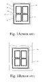
- FIGS. 1 A ⁇ 1 B illustrate a mechanical sealing method in the prior art.
- two liquid crystal substrates 10 (it only shows one liquid crystal substrate 10 in FIG. 1A) which are adhered to be opposed in parallel to each other to form a container 12 have to be thinned by a chemical etching or a Chemical Machine Polishing (CMP), thus the container 12 including a cell 11 needs to prevent a liquid 13 (especially a hydrofluoric acid, HF used in the chemical etching) from permeating into the cell 11 (between the two liquid crystal substrates 10 ). That means a layer or more dummy seal 14 must be coated around a periphery 15 of the substrate 10 for preventing the liquid 13 from permeating thereinto. Further, because a gas inside the container 12 must be exhausted through an exhaust 16 formed by the dummy seal 14 when assembling the two substrates 10 , the exhaust 16 will be sealed off by a sealing glue 17 after assembling.
- CMP Chemical Machine Polishing
- FIG. 1C illustrates another sealing method for the exhaust 16 of the container 12 according to the prior art.
- an obstructive seal 18 paralleled to the dummy seal 14 is utilized to form a narrow channel 19 inside the exhaust 16 for blocking and slowing down the liquid 13 , so that the time for the liquid 13 to permeate into the cell 11 will be extended.
- FIG. 1D illustrates the third sealing method for the exhaust 16 according to the prior art.
- a long seal 181 is utilized to from an extended channel 191 which will also increase the time for the liquid 13 to permeate into the cell.
- the extended channel 191 has a wider width than the narrow channel 19 in FIG. 1C.
- the first sealing off method will increase the complexity of the whole manufacturing processes.
- the second and third methods for forming a narrow channel and an extended channel, although these methods can extend the permeation time of the liquid, these will also increase the exhausting time of the gas in the cell at the same time and then reduce the yield. Furthermore, even though these methods are introduced, the liquid will still permeate into the cell.
- a method for preventing liquid from permeating into a cell for facilitating fabrication of a plurality of planels includes steps of providing a first substrate having a first exhaust area and a plurality of first portions of the planels, providing a second substrate having a second exhaust area and a plurality of second portions of the planels, printing a plurality of orienting films on the plurality of first and second portions of the planels, printing a plurality of thickening films respectively on the first and the second substrates for narrowing an intermediate distance of the first and second exhaust areas to prevent the liquid from permeating into the cell therethrough, coating a dummy seal around a periphery of the second substrate for preventing the liquid permeating into the cell, and assembling the first and the second substrates for forming the cell.
- the plurality of planels are filled therebetween with a plurality of liquid crystal molecules.
- the plurality of liquid crystal molecules can be arranged in response to the plurality of orienting films between the plurality of planels.
- the method further includes a step of coating a frame seal around a periphery of the plurality of planels for filling the plurality of liquid crystal molecules between the plurality of planels.
- the plurality of thickening films are polymer films.
- the plurality of orienting films and the plurality of thickening films are made of a polyimide (PI) and are printed on the first and the second substrates.
- PI polyimide
- each of the plurality of thickening films has a slant end on an inner side thereof with respect to the cell for gradually increasing an intermediate distance of the plurality of thickening films respectively on the first and the second substrates, so that a surface tension and capillarity are utilized to prevent the liquid from permeating into the cell.
- the plurality of thickening films and a surface of the liquid can form an included angle ⁇ c
- a surface on the slant end and a horizontal plane of the plurality of thickening films can form an included angle ⁇ .
- the included angle ⁇ can be greater than ( ⁇ /2 ⁇ c ).
- the first and the second substrates are LCD (Liquid Crystal Display) substrates
- the liquid is a HF (hydrofluoric acid) for proceeding a chemical etching process to reduce a weight of the LCD substrate.
- the first substrate is a TFT (Thin Film Transistor) substrate.
- TFT Thin Film Transistor
- the second substrate is a CF (Color Filter) substrate.
- a method for preventing a liquid from permeating into a cell for facilitating fabrication of a plurality of planels includes steps of providing a first substrate having a first encircling exhaust area and a plurality of first portions of the planels, providing a second substrate having a second encircling exhaust area and a plurality of second portions of the planels, printing a plurality of polyimides on the plurality of first and second portions of the planels, printing a plurality of encircling thickening films respectively on the first and the second substrates for narrowing an intermediate distance of the encircling exhaust areas to prevent the liquid from permeating into the cell therethrough, and assembling the first and the second substrates for forming the cell.
- the method further includes a step of coating a frame seal around a periphery of the plurality of planels for filling the plurality of liquid crystal molecules between the plurality of planels.
- the plurality of encircling thickening films are rectangular circles disposed at the encircling exhaust areas.
- each of the plurality of encircling thickening films has an inner slant circle thereof with respect to the cell for gradually increasing an intermediate distance of the plurality of thickening films respectively on the first and the second substrates, so that a surface tension and capillarity are utilized to prevent the liquid from permeating into the cell.
- the plurality of encircling thickening films and a surface of the liquid can form an included angle ⁇ c
- a surface on the slant circle and a horizontal plane of the plurality of encircling thickening films can form an included angle ⁇ .
- the included angle ⁇ can be greater than ( ⁇ /2 ⁇ c ).
- a structure for preventing a liquid from permeating into a cell with an exhaust outlet includes a first substrate having a plurality of first portions of a plurality of planels, a second substrate having a plurality of second portions of the plurality of planels, a printer for printing a plurality of orienting films on the plurality of first and second portions of the plurality of planels, and two thickening films respectively disposed on the first and the second substrates around the exhaust outlet for narrowing an intermediate distance of the two substrates around the exhaust outlet to prevent the cell from being permeated by the liquid through the exhaust outlet, wherein the first and the second substrates are assembled to form the cell.
- the method further includes a frame seal coated around the periphery of the plurality of planels for filling the plurality of liquid crystal molecules between the plurality of planels.
- each the two thickening films has a slant end on an inner side thereof with respect to the cell for gradually increasing an intermediate distance of the two thickening films, so that a surface tension and capillarity are utilized to prevent the liquid from permeating into the cell.
- the two thickening films and a surface of the liquid can form an included angle ⁇ c
- a surface on the slant end and a horizontal plane of the two thickening films can form an included angle ⁇ .
- the included angle P can be greater than ( ⁇ /2 ⁇ c ).
- the exhaust outlet is an encircling exhaust outlet and the two thickening films are encircling thickening films.
- FIG. 1A is a schematic view showing a method for sealing off the exhaust of the liquid crystal substrates in the prior art
- FIG. 1B is a schematic view showing the substrate immersed in HF according to the prior art
- FIG. 1C is schematic view showing a narrow channel inside the exhaust of the substrate according to the prior art
- FIG. 1D is a schematic view showing an extended channel inside the exhaust of the substrate according to the prior art
- FIGS. 2 A ⁇ 2 D show the manufacturing processes for preventing the cell from permeating in the first preferred embodiment according to the present invention
- FIG. 2E is a schematic view of the SS cross-section in FIG. 2D;
- FIGS. 3 A ⁇ 3 D show the manufacturing processes for preventing the cell from permeating in the second preferred embodiment according to the present invention
- FIG. 3E is a schematic view of the TT cross-section in FIG. 4D;
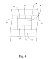
- FIG. 4 is the front view of the exhaust in FIG. 2D according to the present invention.
- FIG. 5 is the cross-section view of the exhaust to show how the liquid flows into the cell according to the present invention
- FIG. 6 is the cross-section view of the exhaust to illustrate how the liquid is blocked by the slant ends of the thickening films when the liquid flows into the cell according to the present invention.
- FIG. 7 shows the comparative plot of the angle ⁇ (in FIG. 5) vs. the liquid volume and the energy at the gas/liquid interface in the first preferred embodiment according to the present invention.
- FIGS. 2 A ⁇ 2 E illustrate a method for preventing liquid from permeating into a cell for facilitating fabrication of a plurality of planels in the first preferred embodiment according to the present invention.
- This method includes steps of (a) providing a first substrate 22 having a first exhaust area 28 and first portions 23 of a plurality of planels 21 ; (b) providing a second substrate 24 having a second exhaust area 29 and second portions 25 of the plurality of planels 21 ; (c) printing a plurality of orienting films 26 , 27 respectively on the first and the second portions 23 , 25 of the plurality of planels 21 (as shown in FIG.
- the method further includes a step (e′) of coating a frame seal 242 around the periphery of the second portions 25 of the plurality of planels 21 for filling the liquid crystal between the plurality of planels 21 .
- each of thickening films 281 , 291 has a slant end 221 , 243 on an inner side thereof with respect to the cell 20 (as shown in FIG. 2E) for gradually increasing the intermediate distance D between the first and the second exhaust areas 28 , 29 .
- the first and the second substrates 22 , 24 can be LCD (Liquid Crystal Display) substrates, and the liquid 13 can be a HF (hydrofluoric acid) for proceeding a chemical etching process to reduce a weight of the glass substrate of LCD.
- the first substrate 22 is a TFT (Thin Film Transistor) substrate
- the second substrate 24 is a CF (Color Filter) substrate.
- each of the plurality of planels 21 comprises the first and the second portions 23 , 25 and the frame seal 242 .
- FIGS. 3 A ⁇ 3 E illustrate the second preferred embodiment according to the present invention which are the method for preventing a liquid from permeating into a cell for facilitating fabrication of a plurality of planels.
- the manufacturing process includes steps of (a) providing a first substrate 32 having a first encircling exhaust area 38 and first portions 33 of a plurality of planels 31 ; (b) providing a second substrate 34 having a second encircling exhaust area 39 and second portions 35 of the plurality of planels 31 ; (c) printing a plurality of orienting films 36 , 37 respectively on the first and the second portions 33 , 35 of the plurality of planels 31 (as shown in FIG.
- each encircling thickening films 381 , 391 is a rectangular circle disposed at the encircling exhaust areas 38 , 39 around the periphery of the first and the second substrates 32 , 34 .
- the method further includes a step (d′) of coating a frame seal 341 around the periphery of the second portions 35 of the plurality of planels 31 for filling the liquid crystal between the plurality of planels 31 .
- each of the encircling thickening films 381 , 391 has an inner slant circle thereof with respect to the cell for gradually increasing the intermediate distance DC between the first and the second exhaust areas 38 , 39 . Consequently, as described above, the dummy seal 241 in FIGS. 2C and 2D are replaced by the encircling thickening films 381 , 391 in FIGS. 3 B ⁇ 3 D for simplifying the whole manufacturing process.
- FIG. 4 shows the front view of the exhaust in FIG. 2D according to the present invention.
- Each of the thickening films 281 , 291 has a thickness greater than 300 ⁇ but less than half the distance between two walls 41 , 42 of the exhaust outlet 40 .
- each of the ends 52 , 53 opposite to the slant ends 50 , 51 of the thickening films 281 , 291 can have a thickness lessened to 500 ⁇ .
- FIGS. 5 and 6 show how the liquid flows into the cell (FIG. 5) and how the liquid is blocked by the slant ends of the thickening films (FIG. 6) when the liquid flows into the cell according to the present invention.
- one of the thickening films 281 , 291 and a surface of the liquid 13 form an included angle ⁇ c
- one of the slant ends 50 , 51 and a horizontal plane of the thickening films 281 , 291 form an included angle ⁇ , wherein the included angle ⁇ is greater than ( ⁇ /2 ⁇ c ).
- FIG. 7 shows the comparative plot of the angle ⁇ (in FIG. 5) vs. the liquid volume and the energy at the gas/liquid interface.
- the intermediate distance h n between the two thickening films is 5 ⁇ m
- ⁇ c is 20°
- w the thickness of the thickening film
- the liquid volume (pL) is greater than 2.00 pL
- the energy (pJ) at the gas/liquid interface will be increased by the increasing ⁇ (the angle ⁇ is increased from 0° to 90°).
- ⁇ ⁇ ⁇ P 2 ⁇ ⁇ la h n ⁇ ( cos ⁇ ⁇ ⁇ c - ⁇ sin ⁇ ⁇ ⁇ ⁇ sin ⁇ ⁇ ⁇ cos ⁇ ⁇ ⁇ + sin ⁇ ⁇ ⁇ sin ⁇ ⁇ ⁇ ⁇ [ ⁇ sin ⁇ ⁇ ⁇ - cos ⁇ ⁇ ⁇ ] )
- h n is the intermediate distance between the two thickening films
- ⁇ la is the energy at the gas/liquid interface
- ⁇ c is the included angle of the liquid surface and the thickening film
- 2 ⁇ is the arc angle of the liquid surface
- ⁇ is the inclined angle of the slant end of the thickening film.
- the slant ends of the thickening films may have different slopes and is unnecessary to be symmetrical, and the shape of the exhaust constituted by the thickening films (and the dummy seals) will not be limited.
- the thickening films can be an encircling one for replacing the dummy seal.
- both the thickening films and the dummy seal are hydrophobic, no matter the liquid is hydrophilic or hydrophobic, it will be blocked at the exhaust.
- the present invention provides a new method and structure for preventing the liquid from permeating through the balance of the surface tension and capillarity at the exhaust which has an imcreasing intermediate distance. And because of this design, the conventional sealing off process can be abbreviated, as well as making a narrow channel and an extended channel. Therefore, the fabrication efficiency of the liquid crystal substrate can be greatly promoted. Consequently, the present invention is suitable for the industrial production, so that it owns the industrial value extremely.
Landscapes
- Physics & Mathematics (AREA)
- Nonlinear Science (AREA)
- Mathematical Physics (AREA)
- Chemical & Material Sciences (AREA)
- Crystallography & Structural Chemistry (AREA)
- General Physics & Mathematics (AREA)
- Optics & Photonics (AREA)
- Engineering & Computer Science (AREA)
- Manufacturing & Machinery (AREA)
- Liquid Crystal (AREA)
Abstract
A method for preventing a liquid from permeating into a cell for facilitating fabrication of a plurality of planels is provided. The method includes steps of providing a first substrate having a first exhaust area and a plurality of first portions of the planels, providing a second substrate having a second exhaust area and a plurality of second portions of the planels, printing a plurality of orienting films on the plurality of first and second portions of the planels, printing a plurality of thickening films respectively on the first and the second substrates for narrowing an intermediate distance of the first and second exhaust areas to prevent the liquid from permeating into the cell therethrough, coating a dummy seal around a periphery of the second substrate for preventing the liquid permeating into the cell, and assembling the first and the second substrates for forming the cell.
Description
- This invention relates to a method for preventing a liquid from permeating, and more particularly to a method for preventing a liquid from permeating into a cell which facilitates fabrication of a plurality of planels.
- Generally, when a container has to be processed in a liquid without being permeated thereby, a sealing for an outlet of the container is always necessary.
- Please refer to FIGS. 1A˜1B which illustrate a mechanical sealing method in the prior art. In some conditions, two liquid crystal substrates 10 (it only shows one
liquid crystal substrate 10 in FIG. 1A) which are adhered to be opposed in parallel to each other to form acontainer 12 have to be thinned by a chemical etching or a Chemical Machine Polishing (CMP), thus thecontainer 12 including acell 11 needs to prevent a liquid 13 (especially a hydrofluoric acid, HF used in the chemical etching) from permeating into the cell 11 (between the two liquid crystal substrates 10). That means a layer or moredummy seal 14 must be coated around aperiphery 15 of thesubstrate 10 for preventing theliquid 13 from permeating thereinto. Further, because a gas inside thecontainer 12 must be exhausted through anexhaust 16 formed by thedummy seal 14 when assembling the twosubstrates 10, theexhaust 16 will be sealed off by asealing glue 17 after assembling. - Please refer to FIG. 1C. FIG. 1C illustrates another sealing method for the
exhaust 16 of thecontainer 12 according to the prior art. In FIG. 1C, anobstructive seal 18 paralleled to thedummy seal 14 is utilized to form anarrow channel 19 inside theexhaust 16 for blocking and slowing down theliquid 13, so that the time for theliquid 13 to permeate into thecell 11 will be extended. And please further refer to FIG. 1D which illustrates the third sealing method for theexhaust 16 according to the prior art. In FIG. 1D, along seal 181 is utilized to from an extendedchannel 191 which will also increase the time for theliquid 13 to permeate into the cell. Thus, the extendedchannel 191 has a wider width than thenarrow channel 19 in FIG. 1C. - However, these three methods described above still have some cons. The first sealing off method will increase the complexity of the whole manufacturing processes. As to the second and third methods, for forming a narrow channel and an extended channel, although these methods can extend the permeation time of the liquid, these will also increase the exhausting time of the gas in the cell at the same time and then reduce the yield. Furthermore, even though these methods are introduced, the liquid will still permeate into the cell.
- Because of the defects described above, the applicant keeps on carving unflaggingly to develop “method for preventing liquid from permeating” through wholehearted experience and research.
- It is an object of the present invention to provide a method for preventing liquid from permeating into a cell by printing a thickening film on an exhaust area of a substrate.
- It is another object of the present invention to narrow and then increase an intermediate distance of the thickening films printed on the two substrates, so that a surface tension and capillarity will be utilized to resist the liquid to permeate into the cell.
- According to an aspect of the present invention, a method for preventing liquid from permeating into a cell for facilitating fabrication of a plurality of planels includes steps of providing a first substrate having a first exhaust area and a plurality of first portions of the planels, providing a second substrate having a second exhaust area and a plurality of second portions of the planels, printing a plurality of orienting films on the plurality of first and second portions of the planels, printing a plurality of thickening films respectively on the first and the second substrates for narrowing an intermediate distance of the first and second exhaust areas to prevent the liquid from permeating into the cell therethrough, coating a dummy seal around a periphery of the second substrate for preventing the liquid permeating into the cell, and assembling the first and the second substrates for forming the cell.
- Preferably, the plurality of planels are filled therebetween with a plurality of liquid crystal molecules.
- Certainly, the plurality of liquid crystal molecules can be arranged in response to the plurality of orienting films between the plurality of planels.
- Preferably, the method further includes a step of coating a frame seal around a periphery of the plurality of planels for filling the plurality of liquid crystal molecules between the plurality of planels.
- Preferably, the plurality of thickening films are polymer films.
- Preferably, the plurality of orienting films and the plurality of thickening films are made of a polyimide (PI) and are printed on the first and the second substrates.
- Preferably, each of the plurality of thickening films has a slant end on an inner side thereof with respect to the cell for gradually increasing an intermediate distance of the plurality of thickening films respectively on the first and the second substrates, so that a surface tension and capillarity are utilized to prevent the liquid from permeating into the cell.
- Certainly, the plurality of thickening films and a surface of the liquid can form an included angle θ c, and a surface on the slant end and a horizontal plane of the plurality of thickening films can form an included angle β.
- Certainly, the included angle β can be greater than (π/2−θ c).
- Preferably, the first and the second substrates are LCD (Liquid Crystal Display) substrates, and the liquid is a HF (hydrofluoric acid) for proceeding a chemical etching process to reduce a weight of the LCD substrate.
- Preferably, the first substrate is a TFT (Thin Film Transistor) substrate.
- Preferably, the second substrate is a CF (Color Filter) substrate.
- In accordance with another aspect of the present invention, a method for preventing a liquid from permeating into a cell for facilitating fabrication of a plurality of planels includes steps of providing a first substrate having a first encircling exhaust area and a plurality of first portions of the planels, providing a second substrate having a second encircling exhaust area and a plurality of second portions of the planels, printing a plurality of polyimides on the plurality of first and second portions of the planels, printing a plurality of encircling thickening films respectively on the first and the second substrates for narrowing an intermediate distance of the encircling exhaust areas to prevent the liquid from permeating into the cell therethrough, and assembling the first and the second substrates for forming the cell.
- Preferably, the method further includes a step of coating a frame seal around a periphery of the plurality of planels for filling the plurality of liquid crystal molecules between the plurality of planels.
- Preferably, the plurality of encircling thickening films are rectangular circles disposed at the encircling exhaust areas.
- Preferably, each of the plurality of encircling thickening films has an inner slant circle thereof with respect to the cell for gradually increasing an intermediate distance of the plurality of thickening films respectively on the first and the second substrates, so that a surface tension and capillarity are utilized to prevent the liquid from permeating into the cell.
- Certainly, the plurality of encircling thickening films and a surface of the liquid can form an included angle θ c, and a surface on the slant circle and a horizontal plane of the plurality of encircling thickening films can form an included angle β.
- Certainly, the included angle β can be greater than (π/2−θ c).
- In accordance with a further aspect of the present invention, a structure for preventing a liquid from permeating into a cell with an exhaust outlet includes a first substrate having a plurality of first portions of a plurality of planels, a second substrate having a plurality of second portions of the plurality of planels, a printer for printing a plurality of orienting films on the plurality of first and second portions of the plurality of planels, and two thickening films respectively disposed on the first and the second substrates around the exhaust outlet for narrowing an intermediate distance of the two substrates around the exhaust outlet to prevent the cell from being permeated by the liquid through the exhaust outlet, wherein the first and the second substrates are assembled to form the cell.
- Preferably, the method further includes a frame seal coated around the periphery of the plurality of planels for filling the plurality of liquid crystal molecules between the plurality of planels.
- Preferably, each the two thickening films has a slant end on an inner side thereof with respect to the cell for gradually increasing an intermediate distance of the two thickening films, so that a surface tension and capillarity are utilized to prevent the liquid from permeating into the cell.
- Certainly, the two thickening films and a surface of the liquid can form an included angle θ c, and a surface on the slant end and a horizontal plane of the two thickening films can form an included angle β.
- Certainly, the included angle P can be greater than (π/2−θ c).
- Preferably, the exhaust outlet is an encircling exhaust outlet and the two thickening films are encircling thickening films.
- The above objects and advantages of the present invention will become more readily apparent to those ordinarily skilled in the art after reviewing the following detailed descriptions and accompanying drawings, in which:
- FIG. 1A is a schematic view showing a method for sealing off the exhaust of the liquid crystal substrates in the prior art;
- FIG. 1B is a schematic view showing the substrate immersed in HF according to the prior art;
- FIG. 1C is schematic view showing a narrow channel inside the exhaust of the substrate according to the prior art;
- FIG. 1D is a schematic view showing an extended channel inside the exhaust of the substrate according to the prior art;
- FIGS. 2A˜2D show the manufacturing processes for preventing the cell from permeating in the first preferred embodiment according to the present invention;
- FIG. 2E is a schematic view of the SS cross-section in FIG. 2D;
- FIGS. 3A˜3D show the manufacturing processes for preventing the cell from permeating in the second preferred embodiment according to the present invention;
- FIG. 3E is a schematic view of the TT cross-section in FIG. 4D;
- FIG. 4 is the front view of the exhaust in FIG. 2D according to the present invention.
- FIG. 5 is the cross-section view of the exhaust to show how the liquid flows into the cell according to the present invention;
- FIG. 6 is the cross-section view of the exhaust to illustrate how the liquid is blocked by the slant ends of the thickening films when the liquid flows into the cell according to the present invention; and
- FIG. 7 shows the comparative plot of the angle β (in FIG. 5) vs. the liquid volume and the energy at the gas/liquid interface in the first preferred embodiment according to the present invention.
- Please refer to FIGS. 2A˜2E which illustrate a method for preventing liquid from permeating into a cell for facilitating fabrication of a plurality of planels in the first preferred embodiment according to the present invention. This method includes steps of (a) providing a
first substrate 22 having afirst exhaust area 28 andfirst portions 23 of a plurality ofplanels 21; (b) providing asecond substrate 24 having asecond exhaust area 29 andsecond portions 25 of the plurality ofplanels 21; (c) printing a plurality of orientingfilms second portions films second exhaust areas 28, 29 (as shown in FIG. 2B) for narrowing an intermediate distance of the exhaust areas to prevent thecell 20 from being permeated by the liquid 13 therethrough; (e) coating a dummy seal 241 (as shown in FIG. 2C) around a periphery of thesecond substrate 24 for preventing the liquid 13 permeating into thecell 20; and (f) assembling the first and thesecond substrates cell 20, wherein the plurality ofplanels 21 are filled therebetween with liquid crystals, the liquid crystals are arranged in response to thickeningfilms planels 21, and the plurality of orientingfilms films second substrates frame seal 242 around the periphery of thesecond portions 25 of the plurality of planels 21 for filling the liquid crystal between the plurality ofplanels 21. Furthermore, each of thickeningfilms slant end second exhaust areas - Of course, the first and the
second substrates first substrate 22 is a TFT (Thin Film Transistor) substrate, and thesecond substrate 24 is a CF (Color Filter) substrate. And, each of the plurality ofplanels 21 comprises the first and thesecond portions frame seal 242. - Please refer to FIGS. 3A˜3E. FIGS. 3A˜3E illustrate the second preferred embodiment according to the present invention which are the method for preventing a liquid from permeating into a cell for facilitating fabrication of a plurality of planels. In this preferred embodiment, the manufacturing process includes steps of (a) providing a
first substrate 32 having a first encirclingexhaust area 38 andfirst portions 33 of a plurality ofplanels 31; (b) providing asecond substrate 34 having a second encirclingexhaust area 39 andsecond portions 35 of the plurality ofplanels 31; (c) printing a plurality of orientingfilms second portions films exhaust areas cell 30 from being permeated by the liquid 13 therethrough; and (e) assembling the first and thesecond substrates cell 30, wherein the plurality ofplanels 31 are filled therebetween with liquid crystals, the liquid crystals are arranged in response to theencircling thickening films planels 31, and the plurality of orientingfilms encircling thickening films second substrates films exhaust areas second substrates frame seal 341 around the periphery of thesecond portions 35 of the plurality of planels 31 for filling the liquid crystal between the plurality ofplanels 31. Furthermore, each of theencircling thickening films second exhaust areas dummy seal 241 in FIGS. 2C and 2D are replaced by the encircling thickeningfilms - Please refer to FIG. 4 which shows the front view of the exhaust in FIG. 2D according to the present invention. Each of the thickening
films walls exhaust outlet 40. However, as shown in FIG. 5, when the thickness of the thickening films is larger than 500 Å, each of theends films - Please refer to FIGS. 5 and 6 which show how the liquid flows into the cell (FIG. 5) and how the liquid is blocked by the slant ends of the thickening films (FIG. 6) when the liquid flows into the cell according to the present invention. In FIG. 5, one of the thickening
films films films cell 20. That means the liquid 13 is blocked thereby. In addition, the theory of the present invention describes above can be seen in U.S. Pat. No. 6,143,248 which described the balance of the surface tension and the capillarity. - Please refer to FIG. 7 which shows the comparative plot of the angle β (in FIG. 5) vs. the liquid volume and the energy at the gas/liquid interface. Take water as an example, under the conditions that the intermediate distance h n between the two thickening films is 5 μm, θc is 20°, and w (the thickness of the thickening film) is 100 μm, and the liquid volume (pL) is greater than 2.00 pL, the energy (pJ) at the gas/liquid interface will be increased by the increasing β (the angle β is increased from 0° to 90°). According to the calculation of Man et al. (P. F. Man et al., MENS Conference, 1998), the lowest difference of the pressure (AP) for overcoming the resistance (produced by the balance of the surface tension and the capillarity for blocking the liquid to further flow in the cell) is:

- Where h n is the intermediate distance between the two thickening films, γla is the energy at the gas/liquid interface, θc is the included angle of the liquid surface and the thickening film, 2α is the arc angle of the liquid surface, and β is the inclined angle of the slant end of the thickening film.
- Thus, in this equation, when h n=5 mm, θc=20°, and β=90°, ΔP will be 10 kPa (1.4 m H2O) which is sufficient for resisting the liquid (water) to flow into the container (namely the cell 20).
- Consequently, because of the resistance described above, the whole manufacturing process will be simplified by abbreviating the sealing off process at the
exhaust areas - Besides, the slant ends of the thickening films may have different slopes and is unnecessary to be symmetrical, and the shape of the exhaust constituted by the thickening films (and the dummy seals) will not be limited. And also, the thickening films can be an encircling one for replacing the dummy seal. Furthermore, because both the thickening films and the dummy seal are hydrophobic, no matter the liquid is hydrophilic or hydrophobic, it will be blocked at the exhaust.
- In view of the aforesaid, the present invention provides a new method and structure for preventing the liquid from permeating through the balance of the surface tension and capillarity at the exhaust which has an imcreasing intermediate distance. And because of this design, the conventional sealing off process can be abbreviated, as well as making a narrow channel and an extended channel. Therefore, the fabrication efficiency of the liquid crystal substrate can be greatly promoted. Consequently, the present invention is suitable for the industrial production, so that it owns the industrial value extremely.
- While the invention has been described in terms of what is presently considered to be the most practical and preferred embodiments, it is to be understood that the invention needs not be limited to the disclosed embodiment. On the contrary, it is intended to cover various modifications and similar arrangements included within the spirit and scope of the appended claims which are to be accorded with the broadest interpretation so as to encompass all such modifications and similar structures.
Claims (32)
1. A method for preventing a liquid from permeating into a cell for facilitating fabrication of a plurality of planels, comprising steps of:
providing a first substrate having a first exhaust area and a plurality of first portions of said planels;
providing a second substrate having a second exhaust area and a plurality of second portions of said planels;
printing a plurality of orienting films on said plurality of first and second portions of said planels;
printing a plurality of thickening films respectively on said first and said second substrates for narrowing an intermediate distance of said first and second exhaust areas to prevent said liquid from permeating into said cell therethrough;
coating a dummy seal around a periphery of said second substrate for preventing said liquid permeating into said cell; and
assembling said first and said second substrates for forming said cell.
2. A method according to claim 1 , wherein said plurality of planels are filled therebetween with a plurality of liquid crystal molecules.
3. A method according to claim 2 , wherein said plurality of liquid crystal molecules are arranged in response to said plurality of orienting films between said plurality of planels.
4. A method according to claim 1 , further comprising a step of coating a frame seal around a periphery of said plurality of planels for filling said plurality of liquid crystal molecules between said plurality of planels.
5. A method according to claim 1 , wherein said plurality of thickening films are polymer films.
6. A method according to claim 1 , wherein said plurality of orienting films and said plurality of thickening films are made of a polyimide (PI) and are printed on said first and said second substrates.
7. A method according to claim 1 , wherein each of said plurality of thickening films has a slant end on an inner side thereof with respect to said cell for gradually increasing an intermediate distance of said plurality of thickening films respectively on said first and said second substrates, so that a surface tension and capillarity are utilized to prevent said liquid from permeating into said cell.
8. A method according to claim 7 , wherein said plurality of thickening films and a surface of said liquid form an included angle θc, and a surface on said slant end and a horizontal plane of said plurality of thickening films form an included angle β.
9. A method according to claim 8 , wherein said included angle β is greater than (π/2−θc).
10. A method according to claim 1 , wherein said first and said second substrates are LCD (Liquid Crystal Display) substrates, and said liquid is a HF (hydrofluoric acid) for proceeding a chemical etching process to reduce a weight of said LCD substrate.
11. A method according to claim 1 , wherein said first substrate is a TFT (Thin Film Transistor) substrate.
12. A method according to claim 1 , wherein said second substrate is a CF (Color Filter) substrate.
13. A method for preventing a liquid from permeating into a cell for facilitating fabrication of a plurality of planels, comprising steps of:
providing a first substrate having a first encircling exhaust area and a plurality of first portions of said planels;
providing a second substrate having a second encircling exhaust area and a plurality of second portions of said planels;
printing a plurality of polyimides on said plurality of first and second portions of said planels;
printing a plurality of encircling thickening films respectively on said first and said second substrates for narrowing an intermediate distance of said encircling exhaust areas to prevent said liquid from permeating into said cell therethrough; and
assembling said first and said second substrates for forming said cell.
14. A method according to claim 13 , wherein said plurality of planels are filled therebetween with a plurality of liquid crystal molecules.
15. A method according to claim 13 , wherein said plurality of liquid crystal molecules are arranged in response to said plurality of polyimides between said plurality of planels.
16. A method according to claim 13 , further comprising a step of coating a frame seal around a periphery of said plurality of planels for filling said plurality of liquid crystal molecules between said plurality of planels.
17. A method according to claim 13 , wherein said plurality of encircling thickening films are encircling polymer films.
18. A method according to claim 13 , wherein said plurality of polyimides and said plurality of encircling thickening films are made of a polyimide (PI) and are all printed on said first and said second substrates.
19. A method according to claim 13 , wherein said plurality of encircling thickening films are rectangular circles disposed at said encircling exhaust areas.
20. A method according to claim 13 , wherein each of said plurality of encircling thickening films has an inner slant circle thereof with respect to said cell for gradually increasing an intermediate distance of said plurality of thickening films respectively on said first and said second substrates, so that a surface tension and capillarity are utilized to prevent said liquid from permeating into said cell.
21. A method according to claim 20 , wherein said plurality of encircling thickening films and a surface of said liquid form an included angle θc, and a surface on said slant circle and a horizontal plane of said plurality of encircling thickening films form an included angle β.
22. A method according to claim 21 , wherein said included angle β is greater than (π/2−θc).
23. A structure for preventing a liquid from permeating into a cell having an exhaust outlet, comprising:
a first substrate having a plurality of first portions of a plurality of planels;
a second substrate having a plurality of second portions of said plurality of planels;
a printer for printing a plurality of orienting films on said plurality of first and second portions of said plurality of planels; and
two thickening films respectively disposed on said first and said second substrates around said exhaust outlet for narrowing an intermediate distance of said two substrates around said exhaust outlet to prevent said cell from being permeated by said liquid through said exhaust outlet,
wherein said first and said second substrates are assembled to form said cell.
24. A structure according to claim 23 , wherein said plurality of planels are filled with a plurality of liquid crystal molecules.
25. A structure according to claim 23 , wherein said plurality of liquid crystal molecules are arranged in response to said plurality of orienting films between said plurality of planels.
26. A structure according to claim 23 , further comprising a frame seal coated around said periphery of said plurality of planels for filling said plurality of liquid crystal molecules between said plurality of planels.
27. A structure according to claim 23 , wherein said two thickening films are two polymer films.
28. A structure according to claim 23 , wherein said plurality of orienting films and said two thickening films are made of a polyimide (PI) and are all printed on said first and said second substrates.
29. A structure according to claim 23 , wherein each said two thickening films has a slant end on an inner side thereof with respect to said cell for gradually increasing an intermediate distance of said two thickening films, so that a surface tension and capillarity are utilized to prevent said liquid from permeating into said cell.
30. A structure according to claim 29 , wherein said two thickening films and a surface of said liquid form an included angle θc, and a surface on said slant end and a horizontal plane of said two thickening films form an included angle β.
31. A method according to claim 30 , wherein said included angle β is greater than (π/2−θc).
32. A structure according to claim 23 , wherein said exhaust outlet is an encircling exhaust outlet and said two thickening films are encircling thickening films.
Applications Claiming Priority (3)
| Application Number | Priority Date | Filing Date | Title |
|---|---|---|---|
| TW091108012A TW594145B (en) | 2002-04-18 | 2002-04-18 | Method for preventing liquid from permeating |
| TW91108012 | 2002-04-18 | ||
| TW91108012A | 2002-04-18 |
Publications (2)
| Publication Number | Publication Date |
|---|---|
| US20030197829A1 true US20030197829A1 (en) | 2003-10-23 |
| US6833902B2 US6833902B2 (en) | 2004-12-21 |
Family
ID=29213283
Family Applications (1)
| Application Number | Title | Priority Date | Filing Date |
|---|---|---|---|
| US10/319,234 Expired - Fee Related US6833902B2 (en) | 2002-04-18 | 2002-12-13 | Structure for preventing a liquid from permeating into a cell |
Country Status (2)
| Country | Link |
|---|---|
| US (1) | US6833902B2 (en) |
| TW (1) | TW594145B (en) |
Cited By (5)
| Publication number | Priority date | Publication date | Assignee | Title |
|---|---|---|---|---|
| US20100033667A1 (en) * | 2008-08-07 | 2010-02-11 | Dongsheng Huang | Substrate for liquid crystal display, manufacturing method thereof and panel |
| US20130027854A1 (en) * | 2011-07-29 | 2013-01-31 | Sony Corporation | Display and electronic unit |
| CN106773333A (en) * | 2016-12-26 | 2017-05-31 | 武汉华星光电技术有限公司 | A kind of display panel to box assemble method |
| CN107991815A (en) * | 2018-01-29 | 2018-05-04 | 深圳市华星光电技术有限公司 | A kind of production method of alignment film, liquid crystal display panel and liquid crystal display |
| US10341663B2 (en) | 2012-01-20 | 2019-07-02 | Sony Corporation | Coefficient coding harmonization in HEVC |
Citations (3)
| Publication number | Priority date | Publication date | Assignee | Title |
|---|---|---|---|---|
| US5464490A (en) * | 1993-08-18 | 1995-11-07 | Casio Computer Co., Ltd. | Process for manufacturing liquid crystal display |
| US5798813A (en) * | 1995-09-21 | 1998-08-25 | Ipics Corporation | Liquid crystal cell and method for producing the same in which a liquid crystal inlet port opening width is larger than an effective display area width |
| US6678029B2 (en) * | 2000-07-28 | 2004-01-13 | International Business Machines Corporation | Liquid crystal cell, display device, and method of fabricating liquid crystal cell with special fill ports |
-
2002
- 2002-04-18 TW TW091108012A patent/TW594145B/en not_active IP Right Cessation
- 2002-12-13 US US10/319,234 patent/US6833902B2/en not_active Expired - Fee Related
Patent Citations (3)
| Publication number | Priority date | Publication date | Assignee | Title |
|---|---|---|---|---|
| US5464490A (en) * | 1993-08-18 | 1995-11-07 | Casio Computer Co., Ltd. | Process for manufacturing liquid crystal display |
| US5798813A (en) * | 1995-09-21 | 1998-08-25 | Ipics Corporation | Liquid crystal cell and method for producing the same in which a liquid crystal inlet port opening width is larger than an effective display area width |
| US6678029B2 (en) * | 2000-07-28 | 2004-01-13 | International Business Machines Corporation | Liquid crystal cell, display device, and method of fabricating liquid crystal cell with special fill ports |
Cited By (11)
| Publication number | Priority date | Publication date | Assignee | Title |
|---|---|---|---|---|
| US20100033667A1 (en) * | 2008-08-07 | 2010-02-11 | Dongsheng Huang | Substrate for liquid crystal display, manufacturing method thereof and panel |
| US8305543B2 (en) * | 2008-08-07 | 2012-11-06 | Beijing Boe Optoelectronics Technology Co., Ltd. | Substrate for liquid crystal display and sealants at opening region with different hardness, manufacturing method thereof and panel |
| US20130027854A1 (en) * | 2011-07-29 | 2013-01-31 | Sony Corporation | Display and electronic unit |
| US9110313B2 (en) * | 2011-07-29 | 2015-08-18 | Sony Corporation | Display and electronic unit |
| US20150277486A1 (en) * | 2011-07-29 | 2015-10-01 | Sony Corporation | Display and electronic unit |
| US9766653B2 (en) * | 2011-07-29 | 2017-09-19 | Sony Corporation | Display and electronic unit |
| US10073490B2 (en) | 2011-07-29 | 2018-09-11 | Sony Corporation | Display and electronic unit |
| US10341663B2 (en) | 2012-01-20 | 2019-07-02 | Sony Corporation | Coefficient coding harmonization in HEVC |
| CN106773333A (en) * | 2016-12-26 | 2017-05-31 | 武汉华星光电技术有限公司 | A kind of display panel to box assemble method |
| CN107991815A (en) * | 2018-01-29 | 2018-05-04 | 深圳市华星光电技术有限公司 | A kind of production method of alignment film, liquid crystal display panel and liquid crystal display |
| WO2019144454A1 (en) * | 2018-01-29 | 2019-08-01 | 深圳市华星光电技术有限公司 | Method for fabricating alignment film and liquid crystal display |
Also Published As
| Publication number | Publication date |
|---|---|
| US6833902B2 (en) | 2004-12-21 |
| TW594145B (en) | 2004-06-21 |
Similar Documents
| Publication | Publication Date | Title |
|---|---|---|
| US9268169B2 (en) | Display panel with pixel define layer, manufacturing method of pixel define layer of display panel, and display device | |
| US6337730B1 (en) | Non-uniformly-rigid barrier wall spacers used to correct problems caused by thermal contraction of smectic liquid crystal material | |
| US7813030B2 (en) | Display and fabricating method thereof | |
| US8755018B2 (en) | Liquid crystal display mother panel comprising primary spacers and secondary spacers wherein the primary spacers are surrounded by a primary sealant element | |
| JP5232498B2 (en) | Liquid crystal display device and manufacturing method thereof | |
| US20080171209A1 (en) | Method for cutting glass laminate | |
| CN113675357A (en) | Shadow mask for patterned vapor deposition of organic light emitting diode material, shadow mask module including the same, and method of manufacturing shadow mask module | |
| US6833902B2 (en) | Structure for preventing a liquid from permeating into a cell | |
| US7867408B2 (en) | Anisotropic wet etching of silicon | |
| CN106853341A (en) | The anode oxide film of fluid penetrable and the fluid penetrable body with anode oxide film | |
| WO2020253327A1 (en) | Display substrate, preparation method thereof and display device | |
| US7760280B2 (en) | Thin film transistor array substrate and method for manufacturing same | |
| US8598581B2 (en) | Thin film transistor substrate and method for manufacturing the same | |
| US6108063A (en) | Method of manufacturing liquid crystal panel using etching to form microlenses, a heat resisting porous substrate, or a barrier film preventing sodium diffusion | |
| US20120113368A1 (en) | Array substrate, liquid crystal panel, and manufacturing method thereof | |
| US20070039920A1 (en) | Method of fabricating nanochannels and nanochannels thus fabricated | |
| US11119352B2 (en) | Color filter substrate and manufacturing method thereof | |
| US7314783B2 (en) | Method of fabricating contact line of liquid crystal display device | |
| US20090022946A1 (en) | Membrane Structure and Method for Manufacturing the Same | |
| US7388642B2 (en) | Seal pattern for liquid crystal display device and forming method thereof | |
| JP4515291B2 (en) | Liquid crystal display | |
| US8089595B2 (en) | Transflective liquid crystal display devices and fabrication methods thereof | |
| WO2011118273A1 (en) | Liquid crystal display device and manufacturing method thereof | |
| WO2011125284A1 (en) | Method for producing lcd panel | |
| US20060139558A1 (en) | Liquid crystal panel with internal baffle-wall |
Legal Events
| Date | Code | Title | Description |
|---|---|---|---|
| AS | Assignment |
Owner name: HANNSTAR DISPLAY CORP., TAIWAN Free format text: ASSIGNMENT OF ASSIGNORS INTEREST;ASSIGNOR:LIANG, GOU-TSAU;REEL/FRAME:013584/0172 Effective date: 20021211 |
|
| FPAY | Fee payment |
Year of fee payment: 4 |
|
| REMI | Maintenance fee reminder mailed | ||
| FPAY | Fee payment |
Year of fee payment: 8 |
|
| REMI | Maintenance fee reminder mailed | ||
| LAPS | Lapse for failure to pay maintenance fees | ||
| STCH | Information on status: patent discontinuation |
Free format text: PATENT EXPIRED DUE TO NONPAYMENT OF MAINTENANCE FEES UNDER 37 CFR 1.362 |
|
| STCH | Information on status: patent discontinuation |
Free format text: PATENT EXPIRED DUE TO NONPAYMENT OF MAINTENANCE FEES UNDER 37 CFR 1.362 |
|
| FP | Lapsed due to failure to pay maintenance fee |
Effective date: 20161221 |