US20030197581A1 - Magnetic device for a magnetic trip unit - Google Patents
Magnetic device for a magnetic trip unit Download PDFInfo
- Publication number
- US20030197581A1 US20030197581A1 US10/063,401 US6340102A US2003197581A1 US 20030197581 A1 US20030197581 A1 US 20030197581A1 US 6340102 A US6340102 A US 6340102A US 2003197581 A1 US2003197581 A1 US 2003197581A1
- Authority
- US
- United States
- Prior art keywords
- magnetic
- circuit breaker
- current
- armature
- reluctance
- Prior art date
- Legal status (The legal status is an assumption and is not a legal conclusion. Google has not performed a legal analysis and makes no representation as to the accuracy of the status listed.)
- Granted
Links
- 230000004907 flux Effects 0.000 claims abstract description 73
- 230000007246 mechanism Effects 0.000 claims abstract description 18
- 238000000034 method Methods 0.000 claims abstract description 9
- 238000004891 communication Methods 0.000 claims abstract description 4
- 239000000463 material Substances 0.000 claims description 10
- 230000035699 permeability Effects 0.000 claims description 9
- 229910000831 Steel Inorganic materials 0.000 claims description 4
- 239000002184 metal Substances 0.000 claims description 4
- 229910052751 metal Inorganic materials 0.000 claims description 4
- 239000010959 steel Substances 0.000 claims description 4
- 238000013459 approach Methods 0.000 claims description 3
- 229920006395 saturated elastomer Polymers 0.000 claims description 2
- 238000009738 saturating Methods 0.000 claims 2
- 230000033001 locomotion Effects 0.000 description 6
- 230000009467 reduction Effects 0.000 description 3
- XEEYBQQBJWHFJM-UHFFFAOYSA-N Iron Chemical compound [Fe] XEEYBQQBJWHFJM-UHFFFAOYSA-N 0.000 description 2
- CWYNVVGOOAEACU-UHFFFAOYSA-N Fe2+ Chemical compound [Fe+2] CWYNVVGOOAEACU-UHFFFAOYSA-N 0.000 description 1
- 230000009286 beneficial effect Effects 0.000 description 1
- 230000008859 change Effects 0.000 description 1
- 230000007812 deficiency Effects 0.000 description 1
- 230000001419 dependent effect Effects 0.000 description 1
- 230000000694 effects Effects 0.000 description 1
- 230000002349 favourable effect Effects 0.000 description 1
- 238000009434 installation Methods 0.000 description 1
- 229910052742 iron Inorganic materials 0.000 description 1
- 238000012986 modification Methods 0.000 description 1
- 230000004048 modification Effects 0.000 description 1
- 230000005405 multipole Effects 0.000 description 1
- 239000012466 permeate Substances 0.000 description 1
- 230000008569 process Effects 0.000 description 1
- 230000035945 sensitivity Effects 0.000 description 1
- 238000001228 spectrum Methods 0.000 description 1
Images


Classifications
-
- H—ELECTRICITY
- H01—ELECTRIC ELEMENTS
- H01H—ELECTRIC SWITCHES; RELAYS; SELECTORS; EMERGENCY PROTECTIVE DEVICES
- H01H71/00—Details of the protective switches or relays covered by groups H01H73/00 - H01H83/00
- H01H71/10—Operating or release mechanisms
- H01H71/12—Automatic release mechanisms with or without manual release
- H01H71/24—Electromagnetic mechanisms
- H01H71/2472—Electromagnetic mechanisms with rotatable armatures
-
- H—ELECTRICITY
- H01—ELECTRIC ELEMENTS
- H01H—ELECTRIC SWITCHES; RELAYS; SELECTORS; EMERGENCY PROTECTIVE DEVICES
- H01H71/00—Details of the protective switches or relays covered by groups H01H73/00 - H01H83/00
- H01H71/10—Operating or release mechanisms
- H01H71/12—Automatic release mechanisms with or without manual release
- H01H71/24—Electromagnetic mechanisms
- H01H71/2436—Electromagnetic mechanisms with a holding and a releasing magnet, the holding force being limited due to saturation of the holding magnet
-
- H—ELECTRICITY
- H01—ELECTRIC ELEMENTS
- H01H—ELECTRIC SWITCHES; RELAYS; SELECTORS; EMERGENCY PROTECTIVE DEVICES
- H01H71/00—Details of the protective switches or relays covered by groups H01H73/00 - H01H83/00
- H01H71/74—Means for adjusting the conditions under which the device will function to provide protection
- H01H71/7463—Adjusting only the electromagnetic mechanism
Definitions
- Circuit breakers typically provide protection against the very high currents produced by short circuits. This type of protection is provided in many circuit breakers by a magnetic trip unit, which trips the circuit breaker's operating mechanism to open the circuit breaker's main current-carrying contacts upon a short circuit condition.
- Modern magnetic trip units include a magnet yoke (anvil) disposed about a current carrying strap, an armature (lever) pivotally disposed near the anvil, and a spring arranged to bias the armature away from the magnet yoke.
- a magnet yoke anvil
- armature an armature
- spring arranged to bias the armature away from the magnet yoke.
- very high currents pass through the strap.
- the increased current causes an increase in the magnetic field about the magnet yoke.
- the magnetic field acts to rapidly draw the armature towards the magnet yoke, against the bias of the spring.
- the end of the armature contacts a trip lever, which is mechanically linked to the circuit breaker operating mechanism. Movement of the trip lever trips the operating mechanism, causing the main current-carrying contacts to open and stop the flow of electrical current to a protected circuit.
- circuit breakers having a magnetic trip unit described above allow for adjusting the air gap distance between the magnet yoke and the armature to obtain different trip set points.
- the trip set point range offered by adjusting the distance between the magnet yoke and the armature is limited because a large trip set point range requires a large air gap adjustment range. Because available space is often limited, a smaller than desired adjustment range results.
- overcurrent protection at a low current trip setting e.g., three times the rated current of the circuit breaker
- the magnetically induced force acting on the armature isn't significant enough to trip the latch system.
- the electrical load of a motor is characterized by a starting (run-up) current and a running current.
- the starting current averages about six times the full load current of the motor, but the peak of the first half cycle, the so-called “inrush” current, can reach values of up to twenty times the full load current.
- the lower overcurrent range for motor protection is commonly 3 ⁇ the full load current of the motor.
- magnetic trip units It is necessary for such magnetic trip units to be reliable at a low overcurrent setting without altering the magnetically induced force acting on the armature at high overcurrent settings.
- magnetic trip units offer a broader spectrum of overcurrent ranges (e.g., for use in motor protection), so that the breaker can offer a broader range to trip at different levels of overcurrent. It is also desired that the magnetic trip units be compact.
- a magnetic trip unit for actuating a latching mechanism to trip a circuit breaker upon an overcurrent condition
- the magnetic trip unit including: a first electrically conductive strap configured to conduct an electrical current; a first magnet yoke disposed proximate to the first electrically conductive strap; and a first armature pivotally disposed proximate to the first magnetic yoke in operable communication with the latching mechanism; the first armature providing a magnetic path having a reluctance to magnetic flux; and the reluctance is adjusted to prevent saturation of the magnetic flux when the current through the strap is a first number times a rated current of the circuit breaker and the reluctance is adjusted to promote saturation of magnetic flux when the current through the strap is a second number times the rated current of the circuit breaker, wherein the first number is a number smaller than the second number.
- a method of increasing an induced magnetic force from a magnet yoke on a pivotally mounted armature of a trip unit in a circuit breaker at a low current without substantially altering the induced magnetic force acting on the armature at a high current comprising: configuring the armature to provide a magnetic path having a reluctance to a magnetic flux; and adjusting the reluctance of the magnetic path to prevent saturation of the magnetic flux when a current through the trip unit is a first number times a rated current of the circuit breaker, and the magnetic path is generally saturated when the current through the circuit breaker is a second number times the rated current, wherein the first number is a number smaller than the second number.
- FIG. 1 is an elevation view of a circuit breaker with a magnetic trip unit
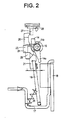
- FIG. 2 is an elevation view of the magnetic trip unit from the circuit breaker of FIG. 1;
- FIG. 3 is a perspective view of a multi-pole circuit breaker including the magnetic trip unit of FIG. 2;
- FIG. 4 is a perspective view of an armature and yoke of the magnetic trip unit in FIG. 3;
- FIG. 5 is a perspective view of an alternative embodiment of the yoke shown in FIG. 4.
- FIG. 6 is a graph illustrating the relationship between the induced force and gap distance of two different armature configurations shown in FIGS. 4 and 5.
- FIG. 1 A circuit breaker 1 equipped with an adjustable magnetic trip unit of the present disclosure is shown in FIG. 1.
- the circuit breaker 1 has a rotary contact arm 2 , which is mounted on an axis 3 of a rotor 4 such that it can rotate.
- the rotor 4 itself is mounted in a terminal housing or cassette (not shown) and has two diametrically opposed satellite axes 5 and 6 , which are also rotated about the axis 3 when the rotor 4 rotates.
- the axis 5 is the point of engagement for a linkage 7 , which is connected to a latch 8 .
- the latch 8 is mounted, such that it can pivot, on an axis 10 positioned on the circuit breaker housing 9 . In the event of an overcurrent or short circuit condition, the latch 8 is released by a latching mechanism 11 , moving the contact arm 2 to the open position shown in FIG. 1.
- the latching mechanism 11 can be actuated by a trip lever 13 that pivots about an axis of rotation 12 .
- the other end of the trip lever 13 contacts a trip shaft 14 , which is mounted on an axis 15 supported by the circuit breaker housing 9 .
- a cam 14 a Disposed on the trip shaft 14 is a cam 14 a, which can be pivoted clockwise in opposition to the force of a torsional spring 14 b wound about the axis 15 .
- a rotational solenoid type magnetic assembly comprising a magnet yoke 16 and a biased armature 18 .
- Magnet yoke 16 encircles a current carrying strap 17 electrically connected to one of the contacts of the circuit breaker 1 .
- the armature 18 Arranged facing the magnet yoke is the armature 18 in the form of a metallic lever, which is hinge-mounted by means of hinge pin sections 19 to hinge knuckles (not shown) formed on the circuit breaker housing 9 .
- the armature 18 is also connected to strap 17 by a spring 20 , which biases the armature 18 in the clockwise direction, away from the magnet yoke 16 .
- armature 18 In its upper region, armature 18 is equipped with a clip 21 rigidly mounted thereon, which can be brought into contact with the cam 14 a by pivoting of the armature in a counter-clockwise direction. Movement of cam 14 a by the armature 18 causes the trip shaft 14 to rotate about axis 15 and thereby actuate the latching mechanism 11 by means of the trip lever 13 . Once actuated, latching mechanism 11 releases latch 8 to initiate the tripping process in circuit breaker 1 . While the clip 21 is described herein as being mounted to armature 18 , the clip 21 can also be formed as one piece with the armature 18 , preferably of metal.
- an adjusting bar 23 extends parallel to the axis 15 and is mounted on the axis 15 , by means of support arms 22 .
- the adjusting bar 23 has an adjusting arm 24 which is threadably engaged to an adjusting screw 25 for calibrating the trip unit.
- Adjusting bar 23 also includes a lever arm 26 which extends to a side of the adjusting bar 23 diametrically opposite adjusting arm 24 .
- a top end of the lever arm 26 is in contact with a cam pin 27 of a rotary knob 28 , which is mounted in a hole in the upper wall of the circuit breaker housing 9 (FIG. 1).
- the surface of the rotary knob 28 is equipped with a slot 29 to make it possible to adjust the rotary knob 28 with the aid of a suitable tool, such as a screwdriver.
- the circuit breaker with adjustable magnetic trip unit shown in FIGS. 1, 2, and 3 operates as follows. First, a person adjusting the circuit breaker 1 by turning rotary egg knob 28 sets the position of the adjusting bar 23 on the axis 15 and thus the distance between the armature 18 and the magnet yoke 16 , as shown in detail in FIG. 2. Because of the relatively greater length of the lever arm 26 as compared to the adjustable arm 24 , the adjustment made by rotary knob 28 is fine. It must be noted here that a coarser adjustment of the gap L between the magnet yoke 16 and the armature 18 can be accomplished by turning the adjusting screw 25 during installation of the trip unit in the circuit breaker housing 9 .
- the trip unit can be arranged for use in a circuit breaker 1 having a plurality of breaker cassettes 30 , with each cassette 30 having its own contact arm 2 and rotor 4 arrangements. While only one cassette 30 is shown, it will be understood that one cassette 30 is used for each phase in the electrical distribution circuit.
- Adjusting bar 23 extends along the row of circuit breaker cassettes 30 , parallel to the axis 15 of the trip shaft 14 . Extending from adjusting bar 23 are several adjusting arms 24 corresponding to the number of circuit breaker cassettes 30 . Also formed on the adjusting bar 23 is one lever arm 26 , which is sufficient to rotate the adjusting bar 23 about axis 15 and, thus, pivot the armatures 18 .
- the tripping sensitivity in each circuit breaker cassette 30 can be adjusted separately by means of the screws 25 carried by each adjusting arm 24 . As a result, individual calibration of each circuit breaker cassette 30 can be undertaken independently of the adjustment of rotary knob 28 .
- FIG. 4 a perspective view of an exemplary embodiment of armature 18 and yoke 16 of a magnetic trip unit assembly is illustrated.
- the magnet yoke 16 is shaped from a ferrous steel plate to define a backwall 40 having side arms 42 , 44 extending generally perpendicularly from backwall 40 towards armature 18 .
- Each of side arms 42 , 44 includes a flange 46 , 48 extending generally perpendicularly therefrom to form a four-sided enclosure.
- Flanges 46 and 48 form an increased pole face area over that offered by side arms 42 , 44 .
- Flanges 46 , 48 further include a gap ‘z’ (pole face gap z) between edges 50 , 52 of the flanges 46 , 48 .
- the armature 18 comprises of generally a flat metallic plate having a portion of material removed in the form of a rectangle 60 .
- a crossbeam component 62 of armature 18 that joins legs 64 , 66 .
- Crossbeam 62 includes an aperture 68 formed therein for attaching one end of spring 20 .
- Clip 21 is formed at a top edge 70 of armature 18 .
- yoke 16 shunts the magnetic flux from yoke 16 onto itself because the flux seeks the path of least magnetic reluctance. Accordingly, the magnetic force of yoke 16 on armature 18 is reduced. However, a further reduction in magnetic force may be needed. To achieve this reduction, an amount of material is removed from armature 18 such that armature 18 does not saturate at low current settings (e.g., having a maximum flux density of approximately 1.9 T (B MAX ) before saturation flux density (B SAT ) of steel at 2.0 T) and saturates at high current settings. Because the armature does not saturate at low current settings, armature 18 does not affect the increase of the magnetically induced force due to the increased pole face area of flanges 46 , 48 acting on cross beam component 62 at low current settings.
- B MAX maximum flux density of approximately 1.9 T
- B SAT saturation flux density
- the reluctance of a magnetic circuit is analogous to the resistance of an electric circuit. Reluctance depends on the geometrical and material properties of the circuit that offer opposition to the presence of magnetic flux. Reluctance of a given part of a magnetic circuit is proportional to its length and inversely proportional to its cross-sectional area and a magnetic property of the given material called its permeability ( ⁇ ). Iron, for example, has an extremely high permeability as compared to air so that it has a comparatively small reluctance, or it offers relatively little opposition to the presence of magnetic flux.
- opposition to an increase in magnetic flux and hence reaching saturation is optionally controlled by selecting the length and cross-sectional area of the magnetic path or selecting a material with a permeability that is near saturation when the gap is small and approaches saturation as the gap increases.
- the magnetic path length is defined by the width of armature 18 and a cross section area 63 of cross beam 62 .
- Cross section area 63 of cross beam 62 is selected to obtain a reluctance that provides favorable magnetic properties at both small gaps L and large gaps L (i.e., first distances and second distances larger than first distances).
- FIG. 5 illustrates a yoke 16 without an increase in pole face area provided by flanges 46 and 48 extending from side arms 42 and 44 .
- FIG. 6 illustrates the relationship between the induced force/torque and gap distance of the two different yoke configurations shown in FIGS. 4 and 5.
- the force/torque versus gap graph 72 shows the different electromagnetic force levels recorded at different magnetic force levels (F m ) (I ⁇ N ampere-turns) at different gap distances (L) utilizing two different yoke 16 configurations (FIGS. 4 and 5).
- the magnetically induced force/torque is substantially increased at small gap distances with a yoke 16 configured having inwardly facing flanges 46 and 48 , while at larger gap distances the magnetically induced force is basically unchanged between the two configurations. More specifically, curves 72 , 76 , and 78 indicate a yoke with flanges 46 and 48 . Curves 84 , 86 , and 88 indicate a yoke without flanges 46 and 48 .
- Curves 74 and 84 illustrate the torque at 3 ⁇ the rated current
- curves 76 and 86 illustrate the torque at 4.5 ⁇ the rated current
- curves 78 and 88 illustrate the torque characteristic at 7.5 ⁇ the rated current.
- the torque at a specific gap was substantially larger, about 10 N mm more, using a yoke with flanges 46 , 48 (FIG. 4) than a yoke 16 without flanges 46 , 48 (FIG. 5) at a first distance such as a low gap setting, i.e., about 2 mm.
- the resultant torque is substantially the same between the two yoke configurations.
- the above described yoke-armature system having a yoke with inwardly facing flanges with a gap z therebetween provides the necessary torque to trip the latch mechanism at small gaps (low current setting), while providing a torque that remains virtually unchanged at larger gaps (high current setting).
Landscapes
- Physics & Mathematics (AREA)
- Electromagnetism (AREA)
- Breakers (AREA)
Abstract
Description
- Circuit breakers typically provide protection against the very high currents produced by short circuits. This type of protection is provided in many circuit breakers by a magnetic trip unit, which trips the circuit breaker's operating mechanism to open the circuit breaker's main current-carrying contacts upon a short circuit condition.
- Modern magnetic trip units include a magnet yoke (anvil) disposed about a current carrying strap, an armature (lever) pivotally disposed near the anvil, and a spring arranged to bias the armature away from the magnet yoke. Upon the occurrence of a short circuit condition, very high currents pass through the strap. The increased current causes an increase in the magnetic field about the magnet yoke. The magnetic field acts to rapidly draw the armature towards the magnet yoke, against the bias of the spring. As the armature moves towards the yoke, the end of the armature contacts a trip lever, which is mechanically linked to the circuit breaker operating mechanism. Movement of the trip lever trips the operating mechanism, causing the main current-carrying contacts to open and stop the flow of electrical current to a protected circuit.
- Currently, circuit breakers having a magnetic trip unit described above allow for adjusting the air gap distance between the magnet yoke and the armature to obtain different trip set points. The trip set point range offered by adjusting the distance between the magnet yoke and the armature is limited because a large trip set point range requires a large air gap adjustment range. Because available space is often limited, a smaller than desired adjustment range results. Furthermore, overcurrent protection at a low current trip setting (e.g., three times the rated current of the circuit breaker) is inhibited because the magnetically induced force acting on the armature isn't significant enough to trip the latch system.
- Those skilled in the art will appreciate that the electrical load of a motor is characterized by a starting (run-up) current and a running current. The starting current averages about six times the full load current of the motor, but the peak of the first half cycle, the so-called “inrush” current, can reach values of up to twenty times the full load current. The lower overcurrent range for motor protection is commonly 3× the full load current of the motor.
- It is necessary for such magnetic trip units to be reliable at a low overcurrent setting without altering the magnetically induced force acting on the armature at high overcurrent settings. In addition, it is desired that magnetic trip units offer a broader spectrum of overcurrent ranges (e.g., for use in motor protection), so that the breaker can offer a broader range to trip at different levels of overcurrent. It is also desired that the magnetic trip units be compact.
- The above discussed and other drawbacks and deficiencies are overcome or alleviated by a magnetic trip unit for actuating a latching mechanism to trip a circuit breaker upon an overcurrent condition, the magnetic trip unit including: a first electrically conductive strap configured to conduct an electrical current; a first magnet yoke disposed proximate to the first electrically conductive strap; and a first armature pivotally disposed proximate to the first magnetic yoke in operable communication with the latching mechanism; the first armature providing a magnetic path having a reluctance to magnetic flux; and the reluctance is adjusted to prevent saturation of the magnetic flux when the current through the strap is a first number times a rated current of the circuit breaker and the reluctance is adjusted to promote saturation of magnetic flux when the current through the strap is a second number times the rated current of the circuit breaker, wherein the first number is a number smaller than the second number.
- In an alternative embodiment, a method of increasing an induced magnetic force from a magnet yoke on a pivotally mounted armature of a trip unit in a circuit breaker at a low current without substantially altering the induced magnetic force acting on the armature at a high current, the method comprising: configuring the armature to provide a magnetic path having a reluctance to a magnetic flux; and adjusting the reluctance of the magnetic path to prevent saturation of the magnetic flux when a current through the trip unit is a first number times a rated current of the circuit breaker, and the magnetic path is generally saturated when the current through the circuit breaker is a second number times the rated current, wherein the first number is a number smaller than the second number.
- Referring to the drawings wherein like elements are numbered alike in the several Figures:
- FIG. 1 is an elevation view of a circuit breaker with a magnetic trip unit;
- FIG. 2 is an elevation view of the magnetic trip unit from the circuit breaker of FIG. 1;
- FIG. 3 is a perspective view of a multi-pole circuit breaker including the magnetic trip unit of FIG. 2;
- FIG. 4 is a perspective view of an armature and yoke of the magnetic trip unit in FIG. 3;
- FIG. 5 is a perspective view of an alternative embodiment of the yoke shown in FIG. 4; and
- FIG. 6 is a graph illustrating the relationship between the induced force and gap distance of two different armature configurations shown in FIGS. 4 and 5.
- A
circuit breaker 1 equipped with an adjustable magnetic trip unit of the present disclosure is shown in FIG. 1. Thecircuit breaker 1 has arotary contact arm 2, which is mounted on an axis 3 of arotor 4 such that it can rotate. Therotor 4 itself is mounted in a terminal housing or cassette (not shown) and has two diametrically opposedsatellite axes 5 and 6, which are also rotated about the axis 3 when therotor 4 rotates. The axis 5 is the point of engagement for a linkage 7, which is connected to alatch 8. Thelatch 8 is mounted, such that it can pivot, on anaxis 10 positioned on the circuit breaker housing 9. In the event of an overcurrent or short circuit condition, thelatch 8 is released by a latching mechanism 11, moving thecontact arm 2 to the open position shown in FIG. 1. - The latching mechanism 11 can be actuated by a trip lever 13 that pivots about an axis of
rotation 12. The other end of the trip lever 13 contacts atrip shaft 14, which is mounted on anaxis 15 supported by the circuit breaker housing 9. Disposed on thetrip shaft 14 is acam 14 a, which can be pivoted clockwise in opposition to the force of atorsional spring 14 b wound about theaxis 15. - Mounted to the circuit breaker housing 9 in the bottom region of the circuit breaker is a rotational solenoid type magnetic assembly comprising a
magnet yoke 16 and abiased armature 18.Magnet yoke 16 encircles a current carryingstrap 17 electrically connected to one of the contacts of thecircuit breaker 1. Arranged facing the magnet yoke is thearmature 18 in the form of a metallic lever, which is hinge-mounted by means ofhinge pin sections 19 to hinge knuckles (not shown) formed on the circuit breaker housing 9. Thearmature 18 is also connected tostrap 17 by aspring 20, which biases thearmature 18 in the clockwise direction, away from themagnet yoke 16. In its upper region,armature 18 is equipped with aclip 21 rigidly mounted thereon, which can be brought into contact with thecam 14 a by pivoting of the armature in a counter-clockwise direction. Movement ofcam 14 a by thearmature 18 causes thetrip shaft 14 to rotate aboutaxis 15 and thereby actuate the latching mechanism 11 by means of the trip lever 13. Once actuated, latching mechanism 11 releaseslatch 8 to initiate the tripping process incircuit breaker 1. While theclip 21 is described herein as being mounted toarmature 18, theclip 21 can also be formed as one piece with thearmature 18, preferably of metal. - Referring now to FIG. 2 and FIG. 3, an adjusting
bar 23 extends parallel to theaxis 15 and is mounted on theaxis 15, by means ofsupport arms 22. The adjustingbar 23 has an adjustingarm 24 which is threadably engaged to an adjustingscrew 25 for calibrating the trip unit. Adjustingbar 23 also includes alever arm 26 which extends to a side of the adjustingbar 23 diametrically opposite adjustingarm 24. A top end of thelever arm 26 is in contact with acam pin 27 of arotary knob 28, which is mounted in a hole in the upper wall of the circuit breaker housing 9 (FIG. 1). The surface of therotary knob 28 is equipped with aslot 29 to make it possible to adjust therotary knob 28 with the aid of a suitable tool, such as a screwdriver. - In the unactuated state of the
magnet yoke 16, which is to say when the contact arm 2 (FIG. 1) is closed and an overcurrent is not present, the adjustingscrew 25 is in constant contact with an angled surface of theclip 21. Contact between adjustingscrew 25 and the angled surface of theclip 21 is ensured by a tensile force exerted by thespring 20 on thearmature 18. The force of the angled surface of theclip 21 on adjustingscrew 25 biases the adjustingbar 23 in a clockwise direction aboutaxis 15, thus forcinglever arm 26 away fromyoke 16 and againstpin 27. In this state, it is possible to change the tilt setting of thearmature 18 either by extending (or retracting) adjustingscrew 25 downward from (upward to) adjustingarm 24, or by rotating the adjustingbar 23 aboutaxis 15 by adjusting therotary knob 28. Thus, the distance L shown in FIG. 2 between thearmature 18 and themagnet yoke 16 is adjusted, thereby setting the current level at which the trip unit responds. - The circuit breaker with adjustable magnetic trip unit shown in FIGS. 1, 2, and 3 operates as follows. First, a person adjusting the
circuit breaker 1 by turningrotary egg knob 28 sets the position of the adjustingbar 23 on theaxis 15 and thus the distance between thearmature 18 and themagnet yoke 16, as shown in detail in FIG. 2. Because of the relatively greater length of thelever arm 26 as compared to theadjustable arm 24, the adjustment made byrotary knob 28 is fine. It must be noted here that a coarser adjustment of the gap L between themagnet yoke 16 and thearmature 18 can be accomplished by turning the adjustingscrew 25 during installation of the trip unit in the circuit breaker housing 9. - In the case of a short circuit, an overcurrent naturally occurs, which flows through the current carrying
strap 17. This activates themagnet yoke 16 to the extent that when a specific current is exceeded, the magnetic force generated by the magnet yoke is sufficient to attract thearmature 18 in opposition to the tensile force exerted by thespring 20.Armature 18 pivots towardsyoke 16, and thecam 14 a is pivoted clockwise in FIG. 1 (counter-clockwise in FIG. 2) by theclip 21 until the trip lever 13 is actuated. Actuation of the trip lever 13 then tilts the latching mechanism 11 such that it in turn can release thelatch 8 for a pivoting motion, upward in FIG. 1, about theaxis 10. This motion is caused by a spring, which is not shown in detail in FIG. 1. The motion of the linkage 7 that is coupled with the pivoting motion of thelatch 8 brings about a rotation of therotor 4 by means of the axis 5, and thus finally a disconnection of thecontact arm 2 from the current carrying straps. - As shown in FIG. 3, the trip unit can be arranged for use in a
circuit breaker 1 having a plurality ofbreaker cassettes 30, with eachcassette 30 having itsown contact arm 2 androtor 4 arrangements. While only onecassette 30 is shown, it will be understood that onecassette 30 is used for each phase in the electrical distribution circuit. Adjustingbar 23 extends along the row ofcircuit breaker cassettes 30, parallel to theaxis 15 of thetrip shaft 14. Extending from adjustingbar 23 are several adjustingarms 24 corresponding to the number ofcircuit breaker cassettes 30. Also formed on the adjustingbar 23 is onelever arm 26, which is sufficient to rotate the adjustingbar 23 aboutaxis 15 and, thus, pivot thearmatures 18. The tripping sensitivity in eachcircuit breaker cassette 30 can be adjusted separately by means of thescrews 25 carried by each adjustingarm 24. As a result, individual calibration of eachcircuit breaker cassette 30 can be undertaken independently of the adjustment ofrotary knob 28. - Referring to FIG. 4, a perspective view of an exemplary embodiment of
armature 18 andyoke 16 of a magnetic trip unit assembly is illustrated. Themagnet yoke 16 is shaped from a ferrous steel plate to define abackwall 40 havingside arms backwall 40 towardsarmature 18. Each ofside arms flange 46, 48 extending generally perpendicularly therefrom to form a four-sided enclosure.Flanges 46 and 48 form an increased pole face area over that offered byside arms Flanges 46, 48 further include a gap ‘z’ (pole face gap z) between edges 50, 52 of theflanges 46, 48. - The
armature 18 comprises of generally a flat metallic plate having a portion of material removed in the form of a rectangle 60. Above rectangle 60 is a crossbeam component 62 ofarmature 18 that joinslegs aperture 68 formed therein for attaching one end ofspring 20.Clip 21 is formed at atop edge 70 ofarmature 18. - Electrical current passing through strap 17 (FIG. 2) induces magnetic flux in
yoke 16 andarmature 18. Accordingly, a magnetic relationship exists between the length of theflanges 46 and 48 of themagnet yoke 16 andarmature 18 that is dependent on gap L that separates theflanges 46, 48 from thearmature 18 and gap z that separate edges 50, 52. The magnetic flux generated within the flux concentratingmagnet yoke 16 seeks the path of least magnetic reluctance. The path of least reluctance is the shorter of the gaps z or L. By maintaining the gap z greater than the gap L, the flux gathers between the flux concentratormagnet side arms arms - Because of the high flux concentration within
arms clip 21 to trip the latch mechanism (i.e.,cam 14 a). The added force is beneficial at low current trip settings (e.g., three times the rated current) where the low current is otherwise not enough to induce sufficient magnetic force onarmature 18 to trip the latch system. For higher trip settings, however, this added force is not needed and may cause damage to the trip latch system. Therefore, thearmature 18 is pivoted away fromyoke 16, thereby increasing gap L until it is greater than gap z. With gap L greater than gap z,yoke 16 shunts the magnetic flux fromyoke 16 onto itself because the flux seeks the path of least magnetic reluctance. Accordingly, the magnetic force ofyoke 16 onarmature 18 is reduced. However, a further reduction in magnetic force may be needed. To achieve this reduction, an amount of material is removed fromarmature 18 such thatarmature 18 does not saturate at low current settings (e.g., having a maximum flux density of approximately 1.9 T (BMAX) before saturation flux density (BSAT) of steel at 2.0 T) and saturates at high current settings. Because the armature does not saturate at low current settings,armature 18 does not affect the increase of the magnetically induced force due to the increased pole face area offlanges 46, 48 acting on cross beam component 62 at low current settings. - More specifically, the reluctance of a magnetic circuit is analogous to the resistance of an electric circuit. Reluctance depends on the geometrical and material properties of the circuit that offer opposition to the presence of magnetic flux. Reluctance of a given part of a magnetic circuit is proportional to its length and inversely proportional to its cross-sectional area and a magnetic property of the given material called its permeability (μ). Iron, for example, has an extremely high permeability as compared to air so that it has a comparatively small reluctance, or it offers relatively little opposition to the presence of magnetic flux. Thus, it will be appreciated that opposition to an increase in magnetic flux and hence reaching saturation, is optionally controlled by selecting the length and cross-sectional area of the magnetic path or selecting a material with a permeability that is near saturation when the gap is small and approaches saturation as the gap increases. The magnetic path length is defined by the width of
armature 18 and across section area 63 of cross beam 62.Cross section area 63 of cross beam 62 is selected to obtain a reluctance that provides favorable magnetic properties at both small gaps L and large gaps L (i.e., first distances and second distances larger than first distances). - By setting the
cross section area 63 based on low current requirements,armature 18 saturates at high current settings which results in a lower relative induced magnetic force. When an emanating magnetic field H permeates through a cross-section area of a medium (i.e., cross section area 63), it converts to magnetic flux density B according to the following formula: B magnetic flux density=μH magnetic field where μ is the permeability of the medium. Flux density (B) is simply the total flux (φ) divided by the cross sectional area (Ae) of the part through which it flows—B=φ/Ae teslas - Initially, as current is increased the flux (φ) increases in proportion to it. At some point, however, further increases in current lead to progressively smaller increases in flux. Eventually, the
armature 18 can make no further contribution to flux growth and any increase thereafter is limited to that provided by the permeability of free space (μ0)—perhaps three orders of magnitude smaller. It will be appreciated that the missing material to formaperture 68 must be accounted for in the minimum cross sectional area (Ae) calculation for the flux density (B) inarmature 18 cross beam component 62. - Turning to FIGS. 5 and 6, FIG. 5 illustrates a
yoke 16 without an increase in pole face area provided byflanges 46 and 48 extending fromside arms gap graph 72 shows the different electromagnetic force levels recorded at different magnetic force levels (Fm) (I×N ampere-turns) at different gap distances (L) utilizing twodifferent yoke 16 configurations (FIGS. 4 and 5). Based on the characteristic curves, one can easily see that the magnetically induced force/torque is substantially increased at small gap distances with ayoke 16 configured having inwardly facingflanges 46 and 48, while at larger gap distances the magnetically induced force is basically unchanged between the two configurations. More specifically, curves 72, 76, and 78 indicate a yoke withflanges 46 and 48.Curves 84, 86, and 88 indicate a yoke withoutflanges 46 and 48.Curves 74 and 84 illustrate the torque at 3× the rated current, curves 76 and 86 illustrate the torque at 4.5× the rated current, and curves 78 and 88 illustrate the torque characteristic at 7.5× the rated current. In each case tested, the torque at a specific gap was substantially larger, about 10 N mm more, using a yoke with flanges 46, 48 (FIG. 4) than ayoke 16 without flanges 46, 48 (FIG. 5) at a first distance such as a low gap setting, i.e., about 2 mm. However, as the gap L increased, the resultant torque is substantially the same between the two yoke configurations. The reduction in the magnetically induced force at the high current settings (large gaps) due to saturation and due to the flux shunt yoke effect described above, allows a magnetic force that remains unchanged at a second distance such as a high current setting (large gap). - Thus, the above described yoke-armature system having a yoke with inwardly facing flanges with a gap z therebetween provides the necessary torque to trip the latch mechanism at small gaps (low current setting), while providing a torque that remains virtually unchanged at larger gaps (high current setting).
- It will be understood that a person skilled in the art may make modifications to the preferred embodiment shown herein within the scope and intent of the claims. While the present invention has been described as carried out in a specific embodiment thereof, it is not intended to be limited thereby but is intended to cover the invention broadly within the scope and spirit of the claims.
Claims (38)
Priority Applications (1)
| Application Number | Priority Date | Filing Date | Title |
|---|---|---|---|
| US10/063,401 US6980069B2 (en) | 2002-04-18 | 2002-04-18 | Magnetic device for a magnetic trip unit |
Applications Claiming Priority (1)
| Application Number | Priority Date | Filing Date | Title |
|---|---|---|---|
| US10/063,401 US6980069B2 (en) | 2002-04-18 | 2002-04-18 | Magnetic device for a magnetic trip unit |
Publications (2)
| Publication Number | Publication Date |
|---|---|
| US20030197581A1 true US20030197581A1 (en) | 2003-10-23 |
| US6980069B2 US6980069B2 (en) | 2005-12-27 |
Family
ID=29214357
Family Applications (1)
| Application Number | Title | Priority Date | Filing Date |
|---|---|---|---|
| US10/063,401 Expired - Lifetime US6980069B2 (en) | 2002-04-18 | 2002-04-18 | Magnetic device for a magnetic trip unit |
Country Status (1)
| Country | Link |
|---|---|
| US (1) | US6980069B2 (en) |
Cited By (10)
| Publication number | Priority date | Publication date | Assignee | Title |
|---|---|---|---|---|
| US20080246565A1 (en) * | 2007-04-05 | 2008-10-09 | Spitsberg Yuri C | Electrical switching apparatus, and trip actuator assembly and reset assembly therefor |
| US20080245649A1 (en) * | 2007-04-05 | 2008-10-09 | Spitsberg Yuri C | Electrical switching apparatus and trip actuator reset assembly therefor |
| US20090115556A1 (en) * | 2007-11-05 | 2009-05-07 | Square D Company | Divided adjustable armature for a circuit breaker |
| US20130228428A1 (en) * | 2012-03-02 | 2013-09-05 | Siemens Aktiengesellshaft | Circuit breaker latching mechanism |
| US8542083B2 (en) * | 2011-09-23 | 2013-09-24 | Eaton Corporation | Collapsible mechanism for circuit breakers |
| US20150179360A1 (en) * | 2013-12-19 | 2015-06-25 | Lsis Co., Ltd. | Instant trip device of circuit breaker |
| US20160196945A1 (en) * | 2015-01-05 | 2016-07-07 | Lsis Co., Ltd. | Instant trip apparatus of molded case circuit breaker |
| US20160260570A1 (en) * | 2015-03-05 | 2016-09-08 | Siemens Industry, Inc. | Circuit breaker including adjustable instantaneous trip level and methods of operating same |
| DE102006042187B4 (en) * | 2006-09-08 | 2016-11-03 | Ls Industrial Systems Co., Ltd. | Immediate release mechanism for a molded case circuit breaker |
| US20170294282A1 (en) * | 2016-04-07 | 2017-10-12 | General Electric Company | Self-resetting biasing devices for current limiting circuit breaker trip systems |
Families Citing this family (5)
| Publication number | Priority date | Publication date | Assignee | Title |
|---|---|---|---|---|
| US20080122563A1 (en) * | 2006-08-28 | 2008-05-29 | Ls Industrial Systems Co., Ltd. | Instantaneous trip mechanism for mould cased circuit breaker |
| US7515025B2 (en) * | 2006-12-20 | 2009-04-07 | General Electric Company | Current trip unit for circuit breaker |
| US8134092B2 (en) * | 2009-08-21 | 2012-03-13 | Schneider Electric USA, Inc. | Circuit breaker cover attachment |
| DE102012200728A1 (en) * | 2012-01-19 | 2013-07-25 | Siemens Aktiengesellschaft | Electric switch |
| EP3373319B1 (en) | 2017-03-09 | 2021-11-10 | LSIS Co., Ltd. | Circuit breaker with instant trip mechanism |
Citations (12)
| Publication number | Priority date | Publication date | Assignee | Title |
|---|---|---|---|---|
| US2824191A (en) * | 1953-02-05 | 1958-02-18 | Fed Electric Prod Co | Circuit breakers |
| US3421123A (en) * | 1967-06-19 | 1969-01-07 | Gen Electric | Electric circuit breaker with magnetic tripping means |
| US4719438A (en) * | 1986-09-30 | 1988-01-12 | Westinghouse Electric Corp. | Circuit breaker with fast trip unit |
| US5250918A (en) * | 1992-05-05 | 1993-10-05 | Square D Company | Automatic miniature circuit breaker with Z-axis assemblage current response mechanism |
| US5381120A (en) * | 1993-11-15 | 1995-01-10 | General Electric Company | Molded case circuit breaker thermal-magnetic trip unit |
| US5394126A (en) * | 1994-04-18 | 1995-02-28 | Eaton Corporatiion | Circuit breaker with improved magnetic trip assembly |
| US5670922A (en) * | 1996-05-23 | 1997-09-23 | General Electric Company | Circuit breaker magnetic trip unit |
| US5870008A (en) * | 1997-02-21 | 1999-02-09 | General Electric Company | Residential circuit breaker having an enhanced thermal-magnetic trip unit |
| US6194982B1 (en) * | 2000-01-31 | 2001-02-27 | Eaton Corporation | Circuit interrupter with a magnetically-induced automatic trip assembly implementing a spring clamp |
| US6218920B1 (en) * | 1999-02-01 | 2001-04-17 | General Electric Company | Circuit breaker with adjustable magnetic trip unit |
| US20030174033A1 (en) * | 2002-03-12 | 2003-09-18 | Christian Daehler | Motor protection trip unit |
| US6636133B2 (en) * | 2001-09-14 | 2003-10-21 | Square D Company | PTC terminals |
-
2002
- 2002-04-18 US US10/063,401 patent/US6980069B2/en not_active Expired - Lifetime
Patent Citations (12)
| Publication number | Priority date | Publication date | Assignee | Title |
|---|---|---|---|---|
| US2824191A (en) * | 1953-02-05 | 1958-02-18 | Fed Electric Prod Co | Circuit breakers |
| US3421123A (en) * | 1967-06-19 | 1969-01-07 | Gen Electric | Electric circuit breaker with magnetic tripping means |
| US4719438A (en) * | 1986-09-30 | 1988-01-12 | Westinghouse Electric Corp. | Circuit breaker with fast trip unit |
| US5250918A (en) * | 1992-05-05 | 1993-10-05 | Square D Company | Automatic miniature circuit breaker with Z-axis assemblage current response mechanism |
| US5381120A (en) * | 1993-11-15 | 1995-01-10 | General Electric Company | Molded case circuit breaker thermal-magnetic trip unit |
| US5394126A (en) * | 1994-04-18 | 1995-02-28 | Eaton Corporatiion | Circuit breaker with improved magnetic trip assembly |
| US5670922A (en) * | 1996-05-23 | 1997-09-23 | General Electric Company | Circuit breaker magnetic trip unit |
| US5870008A (en) * | 1997-02-21 | 1999-02-09 | General Electric Company | Residential circuit breaker having an enhanced thermal-magnetic trip unit |
| US6218920B1 (en) * | 1999-02-01 | 2001-04-17 | General Electric Company | Circuit breaker with adjustable magnetic trip unit |
| US6194982B1 (en) * | 2000-01-31 | 2001-02-27 | Eaton Corporation | Circuit interrupter with a magnetically-induced automatic trip assembly implementing a spring clamp |
| US6636133B2 (en) * | 2001-09-14 | 2003-10-21 | Square D Company | PTC terminals |
| US20030174033A1 (en) * | 2002-03-12 | 2003-09-18 | Christian Daehler | Motor protection trip unit |
Cited By (19)
| Publication number | Priority date | Publication date | Assignee | Title |
|---|---|---|---|---|
| DE102006042187B4 (en) * | 2006-09-08 | 2016-11-03 | Ls Industrial Systems Co., Ltd. | Immediate release mechanism for a molded case circuit breaker |
| US20080246565A1 (en) * | 2007-04-05 | 2008-10-09 | Spitsberg Yuri C | Electrical switching apparatus, and trip actuator assembly and reset assembly therefor |
| US20080245649A1 (en) * | 2007-04-05 | 2008-10-09 | Spitsberg Yuri C | Electrical switching apparatus and trip actuator reset assembly therefor |
| US7518476B2 (en) * | 2007-04-05 | 2009-04-14 | Eaton Corporation | Electrical switching apparatus and trip actuator reset assembly therefor |
| US7570139B2 (en) * | 2007-04-05 | 2009-08-04 | Eaton Corporation | Electrical switching apparatus, and trip actuator assembly and reset assembly therefor |
| US20090115556A1 (en) * | 2007-11-05 | 2009-05-07 | Square D Company | Divided adjustable armature for a circuit breaker |
| US20100188176A1 (en) * | 2007-11-05 | 2010-07-29 | Schneider Electric USA, Inc. | Divided adjustable armature for a circuit breaker |
| US8040209B2 (en) * | 2007-11-05 | 2011-10-18 | Salaheddine Faik | Divided adjustable armature for a circuit breaker |
| US8542083B2 (en) * | 2011-09-23 | 2013-09-24 | Eaton Corporation | Collapsible mechanism for circuit breakers |
| US9171684B2 (en) * | 2012-03-02 | 2015-10-27 | Siemens Aktiengesellschaft | Circuit breaker latching mechanism |
| US20130228428A1 (en) * | 2012-03-02 | 2013-09-05 | Siemens Aktiengesellshaft | Circuit breaker latching mechanism |
| US20150179360A1 (en) * | 2013-12-19 | 2015-06-25 | Lsis Co., Ltd. | Instant trip device of circuit breaker |
| US9368305B2 (en) * | 2013-12-19 | 2016-06-14 | Lsis Co., Ltd. | Instant trip device of circuit breaker |
| US20160196945A1 (en) * | 2015-01-05 | 2016-07-07 | Lsis Co., Ltd. | Instant trip apparatus of molded case circuit breaker |
| US9711313B2 (en) * | 2015-01-05 | 2017-07-18 | Lsis Co., Ltd. | Instant trip apparatus of molded case circuit breaker |
| US20160260570A1 (en) * | 2015-03-05 | 2016-09-08 | Siemens Industry, Inc. | Circuit breaker including adjustable instantaneous trip level and methods of operating same |
| US9595410B2 (en) * | 2015-03-05 | 2017-03-14 | Siemens Industry, Inc. | Circuit breaker including adjustable instantaneous trip level and methods of operating same |
| US20170294282A1 (en) * | 2016-04-07 | 2017-10-12 | General Electric Company | Self-resetting biasing devices for current limiting circuit breaker trip systems |
| US9899176B2 (en) * | 2016-04-07 | 2018-02-20 | General Electric Company | Self-resetting biasing devices for current limiting circuit breaker trip systems |
Also Published As
| Publication number | Publication date |
|---|---|
| US6980069B2 (en) | 2005-12-27 |
Similar Documents
| Publication | Publication Date | Title |
|---|---|---|
| US6980069B2 (en) | Magnetic device for a magnetic trip unit | |
| US6218920B1 (en) | Circuit breaker with adjustable magnetic trip unit | |
| US5894259A (en) | Thermal trip unit with magnetic shield and circuit breaker incorporating same | |
| US5831501A (en) | Adjustable trip unit and circuit breaker incorporating same | |
| US4983939A (en) | Circuit breaker with adjustable low magnetic trip | |
| US5793026A (en) | Magnetic trip assembly and circuit breaker incorporating same | |
| US4951015A (en) | Circuit breaker with moving magnetic core for low current magnetic trip | |
| CA2899773C (en) | Bimetal and magnetic armature providing an arc splatter resistant offset therebetween, and circuit breaker including the same | |
| JPS63102118A (en) | circuit breaker | |
| US4267539A (en) | Circuit breaker having a cam for external adjustment of its trip point | |
| EP0276074A2 (en) | Circuit breaker with magnetic shunt hold back circuits | |
| CA2495605A1 (en) | An adjustable magnetic trip unit and a circuit breaker incorporating the same | |
| JP2000003655A (en) | Circuit breaker trip crossbar | |
| US5471184A (en) | Circuit breaker | |
| US6842096B2 (en) | Circuit breaker magnetic trip assembly | |
| US3959754A (en) | Circuit breaker with improved trip means | |
| CA2457512A1 (en) | Magnetic member, circuit breaker employing the same, and method of manufacturing the same | |
| JPS5815894B2 (en) | electromagnetic contactor | |
| KR100421909B1 (en) | circuit trip device with function for controlling trip time in MCCB | |
| US4630017A (en) | Magnetic structure for calibrating a circuit breaker | |
| US4326183A (en) | Circuit breaker with self contained adjustable bimetal | |
| US4521756A (en) | Circuit breaker having increased contact opening velocity at trip operation | |
| US5428329A (en) | Springclip means for a latchable operating mechanism on a circuit breaker | |
| JP3484028B2 (en) | Circuit breaker | |
| JPH0749714Y2 (en) | Electromagnetic trip device for circuit breaker |
Legal Events
| Date | Code | Title | Description |
|---|---|---|---|
| AS | Assignment |
Owner name: GENERAL ELECTRIC COMPANY, NEW YORK Free format text: ASSIGNMENT OF ASSIGNORS INTEREST;ASSIGNORS:O'KEEFFE, THOMAS GARY;DAEHLER, CHRISTIAN;SAHU, BIRANCHI NARAYANA;AND OTHERS;REEL/FRAME:012601/0137;SIGNING DATES FROM 20020322 TO 20020412 |
|
| FEPP | Fee payment procedure |
Free format text: PAYOR NUMBER ASSIGNED (ORIGINAL EVENT CODE: ASPN); ENTITY STATUS OF PATENT OWNER: LARGE ENTITY |
|
| STCF | Information on status: patent grant |
Free format text: PATENTED CASE |
|
| CC | Certificate of correction | ||
| FPAY | Fee payment |
Year of fee payment: 4 |
|
| FPAY | Fee payment |
Year of fee payment: 8 |
|
| FPAY | Fee payment |
Year of fee payment: 12 |
|
| AS | Assignment |
Owner name: ABB SCHWEIZ AG, SWITZERLAND Free format text: ASSIGNMENT OF ASSIGNORS INTEREST;ASSIGNOR:GENERAL ELECTRIC COMPANY;REEL/FRAME:052431/0538 Effective date: 20180720 |
|
| AS | Assignment |
Owner name: ABB S.P.A., ITALY Free format text: ASSIGNMENT OF ASSIGNORS INTEREST;ASSIGNOR:ABB SCHWEIZ AG;REEL/FRAME:058878/0740 Effective date: 20211108 |