US20030197082A1 - Magnetic tape drive for preventing a flange spacer from being stripped off - Google Patents
Magnetic tape drive for preventing a flange spacer from being stripped off Download PDFInfo
- Publication number
- US20030197082A1 US20030197082A1 US10/409,195 US40919503A US2003197082A1 US 20030197082 A1 US20030197082 A1 US 20030197082A1 US 40919503 A US40919503 A US 40919503A US 2003197082 A1 US2003197082 A1 US 2003197082A1
- Authority
- US
- United States
- Prior art keywords
- arm
- magnetic tape
- flange
- base
- medium
- Prior art date
- Legal status (The legal status is an assumption and is not a legal conclusion. Google has not performed a legal analysis and makes no representation as to the accuracy of the status listed.)
- Abandoned
Links
- 125000006850 spacer group Chemical group 0.000 title claims abstract description 31
- 239000002783 friction material Substances 0.000 claims description 8
- 239000000463 material Substances 0.000 claims description 4
- 229910052731 fluorine Inorganic materials 0.000 claims description 3
- 239000011737 fluorine Substances 0.000 claims description 3
- PXGOKWXKJXAPGV-UHFFFAOYSA-N Fluorine Chemical compound FF PXGOKWXKJXAPGV-UHFFFAOYSA-N 0.000 claims 2
- 238000010586 diagram Methods 0.000 description 8
- 239000000203 mixture Substances 0.000 description 2
- YCKRFDGAMUMZLT-UHFFFAOYSA-N Fluorine atom Chemical compound [F] YCKRFDGAMUMZLT-UHFFFAOYSA-N 0.000 description 1
- 238000004519 manufacturing process Methods 0.000 description 1
- 239000002184 metal Substances 0.000 description 1
- 238000000034 method Methods 0.000 description 1
- 239000000843 powder Substances 0.000 description 1
Images


Classifications
-
- G—PHYSICS
- G11—INFORMATION STORAGE
- G11B—INFORMATION STORAGE BASED ON RELATIVE MOVEMENT BETWEEN RECORD CARRIER AND TRANSDUCER
- G11B15/00—Driving, starting or stopping record carriers of filamentary or web form; Driving both such record carriers and heads; Guiding such record carriers or containers therefor; Control thereof; Control of operating function
- G11B15/60—Guiding record carrier
- G11B15/66—Threading; Loading; Automatic self-loading
- G11B15/67—Threading; Loading; Automatic self-loading by extracting end of record carrier from container or spool
- G11B15/673—Threading end of record carrier externally to single reel
-
- G—PHYSICS
- G11—INFORMATION STORAGE
- G11B—INFORMATION STORAGE BASED ON RELATIVE MOVEMENT BETWEEN RECORD CARRIER AND TRANSDUCER
- G11B15/00—Driving, starting or stopping record carriers of filamentary or web form; Driving both such record carriers and heads; Guiding such record carriers or containers therefor; Control thereof; Control of operating function
- G11B15/60—Guiding record carrier
- G11B15/66—Threading; Loading; Automatic self-loading
- G11B15/67—Threading; Loading; Automatic self-loading by extracting end of record carrier from container or spool
- G11B15/672—Extracting end of record carrier from container or single reel
Definitions
- the present invention relates to a magnetic tape drive, and more particularly, to a magnetic tape drive for writing data or reading recorded data by a magnetic head.
- a magnetic tape drive draws out a magnetic tape from a medium, and writes data or reads recorded data on the magnetic tape by a magnetic head. After the magnetic tape drive has performed a data writing operation and the like, it reels in and stores the magnetic tape into the medium.
- an arm motor 7 is fixed on a base 1 .
- the arm motor 7 has an arm 2 which turns round an axis of the arm motor 7 .
- the arm 2 has an arm pin 2 b fixed to it.
- the arm pin 2 b has a leader block 2 a which travels around the arm axis along an arm pin locus 4 .
- a take-up reel 6 and a guide roller 10 are attached to the base 1 .
- a medium 5 is set on the base 1 by a separate manual or automatic mechanism.
- a leader pin 5 a is fixed to the head end of a magnetic tape 5 b of the medium 5 .
- the base 1 and a base contact face 1 a are formed into one body.
- Flange spacers 8 and 9 for positioning the bottom face of the arm 2 are stuck to the base contact face 1 a so as to prevent wear powder from being generated by friction between the arm 2 and the base contact face 1 a.
- the arm motor 7 turns around the arm axis, and the arm pin 2 b passes before the guide roller 10 (FIG. 5( b )) and moves along the arm pin locus 4 , drawing the arm pin locus 4 from position “A” toward position “B” (FIG. 5( c )).
- the present invention has an object to provide a magnetic tape drive for preventing a flange spacer from being stripped off.
- a magnetic tape drive holds a leader pin provided on a head end of a magnetic tape stored in a medium.
- the drive includes an arm arranged to be rotatable about an axis and positioned so that the arm can draw out said magnetic tape from the medium by engaging the leader pin and rotating, a base to which the arm is rotatably attached, and a flange spacer arranged between the arm and the base. The flange surrounds the axis about which the arm is rotatable.
- FIG. 1( a ) is a plan view showing a schematic composition of a magnetic tape drive of an embodiment of the present invention
- FIG. 1( b ) is a side view of the vicinity of an arm 2 of FIG. 1( a );
- FIG. 2 is a side view of FIG. 3( b );
- FIG. 3( a ) is a diagram showing the movement of the arm 2 of FIG. 1( a );
- FIG. 3( b ) is a diagram showing the movement of the arm 2 of FIG. 1( a );
- FIG. 3( c ) is a diagram showing the movement of the arm 2 of FIG. 1( a );
- FIG. 3( d ) is a diagram showing the movement of the arm 2 of FIG. 1( a );
- FIG. 4( a ) is a plan view showing a schematic composition of a conventional magnetic tape drive
- FIG. 4( b ) is a side view of the vicinity of an arm of FIG. 4( a );
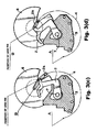
- FIG. 5( a ) is a diagram showing the movement of an arm 2 of FIG. 4( a );
- FIG. 5( b ) is a diagram showing the movement of an arm 2 of FIG. 4( a );
- FIG. 5( c ) is a diagram showing the movement of an arm 2 of FIG. 4( a );
- FIG. 5( d ) is a diagram showing the movement of an arm 2 of FIG. 4( a );
- FIG. 6 is side views showing states before and after FIG. 5( b );
- FIG. 7 is a plan view of the flange spacer 3 of FIG. 1
- an arm motor 7 is fixed on a base 1 .
- An arm 2 which rotates around an axis of the motor 7 , is attached to the arm motor 7 .
- An arm pin 2 b is fixed to the arm 2 .
- a leader block 2 a which travels around the arm axis along a locus 4 is fixed to the arm pin 2 b.
- a take-up reel 6 and a guide roller 10 are attached to the base 1 .
- a medium 5 is set on the base 1 by a separate manual or automatic mechanism.
- a leader pin 5 a is fixed to the head end of a magnetic tape 5 b of the medium 5 .
- the base 1 and a base contact face 1 a are formed into one body.
- a flange spacer 3 of a low-friction material is stuck to the base contact face 1 a .
- the flange spacer 3 may be of a rigid material such as a metal plate material having such a low-friction material as fluorine applied to it.
- the flange spacer 3 may be replaced with two or more separate flange spacers.
- the flange spacer 3 has an edge rounded according to the shape of the base contact face 1 a .
- the flange spacer may be made somewhat larger in size so as to cover the side face of the base contact face 1 a .
- the flange spacer 3 may be replaced with two or more separate flange spacers. Because of this structure, the flange spacer 3 is difficult to delaminate from the base contact face 1 a also in a process of manufacturing a magnetic tape drive.
- the leader block 2 a moves also from position “B” toward position “A” along the arm pin locus 4 .
- a magnetic tape reeling motor (not shown) is attached to the medium 5 so as to prevent the magnetic tape drawn out from the medium 5 from loosening at this time.
- the arm 2 since the arm 2 does not touch the side face of the flange spacer 3 , the flange spacer 3 does not to delaminate from the base contact face 1 a.
Landscapes
- Magnetic Record Carriers (AREA)
- Registering, Tensioning, Guiding Webs, And Rollers Therefor (AREA)
- Moving Of Heads (AREA)
Abstract
A magnetic tape drive prevents a flange spacer from being stripped off. The drive holds a leader pin provided on a head end of a magnetic tape stored in a medium. The drive includes an arm arranged to be rotatable about an axis and positioned so that the arm can draw out said magnetic tape from the medium by engaging the leader pin and rotating, a base to which the arm is rotatably attached, and the flange spacer arranged between the arm and the base. The flange surrounds the axis about which the arm is rotatable.
Description
- The present invention relates to a magnetic tape drive, and more particularly, to a magnetic tape drive for writing data or reading recorded data by a magnetic head.
- Normally, a magnetic tape drive draws out a magnetic tape from a medium, and writes data or reads recorded data on the magnetic tape by a magnetic head. After the magnetic tape drive has performed a data writing operation and the like, it reels in and stores the magnetic tape into the medium.
- It should be noted that an operation of moving a leader block provided on a head end of a magnetic tape from a medium in a state where the leader block is held by an arm being attachable to and detachable from the leader block at the time of drawing out the magnetic tape and thereby drawing out the magnetic tape from the medium and fixing it on a take-up reel is referred to as “threading”. On the other hand, an operation of moving the arm in the opposite direction to the direction of “threading” and storing the magnetic tape fixed on the take-up reel into the medium is referred to as “unthreading”.
- Referring to FIG. 4( a) and FIG. 4(b), in a conventional magnetic tape drive, an
arm motor 7 is fixed on abase 1. Thearm motor 7 has anarm 2 which turns round an axis of thearm motor 7. Thearm 2 has anarm pin 2 b fixed to it. Thearm pin 2 b has aleader block 2 a which travels around the arm axis along anarm pin locus 4. - A take-
up reel 6 and aguide roller 10 are attached to thebase 1. Amedium 5 is set on thebase 1 by a separate manual or automatic mechanism. Aleader pin 5 a is fixed to the head end of amagnetic tape 5 b of themedium 5. - The
base 1 and abase contact face 1 a are formed into one body.Flange spacers arm 2 are stuck to thebase contact face 1 a so as to prevent wear powder from being generated by friction between thearm 2 and thebase contact face 1 a. - In operation, referring to FIG. 5( a), first, when the
medium 5 is set on thebase 1, theleader block 2 a waiting at position “A” is engaged with theleader pin 5 a on the head end of themagnetic tape 5 b. - After this, the
arm motor 7 turns around the arm axis, and thearm pin 2 b passes before the guide roller 10 (FIG. 5(b)) and moves along thearm pin locus 4, drawing thearm pin locus 4 from position “A” toward position “B” (FIG. 5(c)). - Then, referring to FIG. 5( d), the
magnetic tape 5 b is fixed to the take-up reel 6 at position “B”. - However, the prior art has a problem. Referring to FIG. 5( b), there is space between the
flange spacers arm 2. Here, when there is a gap around the fulcrum of thearm 2, the arm2 is inclined downward by weight of theleader block 2 a. - Due to this, as shown in FIG. 6, “threading” or “unthreading” of the
arm 2 has been sometimes hindered by the fact that thearm 2 is caught by a side face of theflange spacer 9 and theflange spacer 9 is stripped off from thebase contact face 1 a. - The present invention has an object to provide a magnetic tape drive for preventing a flange spacer from being stripped off.
- According to one embodiment of the present invention, a magnetic tape drive holds a leader pin provided on a head end of a magnetic tape stored in a medium. The drive includes an arm arranged to be rotatable about an axis and positioned so that the arm can draw out said magnetic tape from the medium by engaging the leader pin and rotating, a base to which the arm is rotatably attached, and a flange spacer arranged between the arm and the base. The flange surrounds the axis about which the arm is rotatable.
- These and other objects, features and advantages of the invention will become more apparent from the following detailed description when taken in conjunction with the accompanying drawings, in which:
- FIG. 1( a) is a plan view showing a schematic composition of a magnetic tape drive of an embodiment of the present invention;
- FIG. 1( b) is a side view of the vicinity of an
arm 2 of FIG. 1(a); - FIG. 2 is a side view of FIG. 3( b);
- FIG. 3( a) is a diagram showing the movement of the
arm 2 of FIG. 1(a); - FIG. 3( b) is a diagram showing the movement of the
arm 2 of FIG. 1(a); - FIG. 3( c) is a diagram showing the movement of the
arm 2 of FIG. 1(a); - FIG. 3( d) is a diagram showing the movement of the
arm 2 of FIG. 1(a); - FIG. 4( a) is a plan view showing a schematic composition of a conventional magnetic tape drive;
- FIG. 4( b) is a side view of the vicinity of an arm of FIG. 4(a);
- FIG. 5( a) is a diagram showing the movement of an
arm 2 of FIG. 4(a); - FIG. 5( b) is a diagram showing the movement of an
arm 2 of FIG. 4(a); - FIG. 5( c) is a diagram showing the movement of an
arm 2 of FIG. 4(a); - FIG. 5( d) is a diagram showing the movement of an
arm 2 of FIG. 4(a); - FIG. 6 is side views showing states before and after FIG. 5( b); and
- FIG. 7 is a plan view of the
flange spacer 3 of FIG. 1 - The present invention will be now explained in detail below with reference to the accompanying drawings.
- Referring to FIG. 1( a) and FIG. 1(b), in a magnetic tape drive of this embodiment, an
arm motor 7 is fixed on abase 1. Anarm 2, which rotates around an axis of themotor 7, is attached to thearm motor 7. Anarm pin 2 b is fixed to thearm 2. Aleader block 2 a, which travels around the arm axis along alocus 4 is fixed to thearm pin 2 b. - A take-
up reel 6 and aguide roller 10 are attached to thebase 1. Amedium 5 is set on thebase 1 by a separate manual or automatic mechanism. Aleader pin 5 a is fixed to the head end of amagnetic tape 5 b of themedium 5. - The
base 1 and abase contact face 1 a are formed into one body. Aflange spacer 3 of a low-friction material is stuck to thebase contact face 1 a. Theflange spacer 3 may be of a rigid material such as a metal plate material having such a low-friction material as fluorine applied to it. Alternatively, theflange spacer 3 may be replaced with two or more separate flange spacers. - Referring to FIG. 7, the
flange spacer 3 has an edge rounded according to the shape of thebase contact face 1 a. Alternatively or in addition, the flange spacer may be made somewhat larger in size so as to cover the side face of thebase contact face 1 a. In such a case also, theflange spacer 3 may be replaced with two or more separate flange spacers. Because of this structure, theflange spacer 3 is difficult to delaminate from thebase contact face 1 a also in a process of manufacturing a magnetic tape drive. - In operation, referring to FIG. 3( a), first, when the
medium 5 is set to thebase 1, theleader block 2 a waiting at position “A” is engaged with theleader pin 5 a on the head end of themagnetic tape 5 b. After this, thearm motor 7 rotates around the axis, and thearm pin 2 b passes before the guide roller 10 (FIG. 3(b)) and moves along thearm pin locus 4, drawing theleader block 2 a from position “A” toward position “B” (FIG. 3(c)). Then, themagnetic tape 5 b is fixed to the take-up reel 6 at position “B” (FIG. 3(d)). - The leader block 2 a moves also from position “B” toward position “A” along the
arm pin locus 4. A magnetic tape reeling motor (not shown) is attached to the medium 5 so as to prevent the magnetic tape drawn out from the medium 5 from loosening at this time. - As shown in FIG. 2, according to a fact that the
flange spacer 3 is provided between thearm 2 and thebase contact face 1 a all along the route of movement of thearm 2, since thearm 2 moves between position “A” and position “B” while being in contact with theflange spacer 3, thearm 2 is prevented from being inclined downward due to weight of theleader block 2 a. - As described above, since the
arm 2 does not touch the side face of theflange spacer 3, theflange spacer 3 does not to delaminate from thebase contact face 1 a. - While this invention has been described in connection with the preferred embodiments described above, it will now be possible for those skilled in the art to put this invention into practice in various other manners.
Claims (12)
1. A magnetic tape drive, which holds a leader pin provided on a head end of a magnetic tape stored in a medium, comprising:
an arm arranged to be rotatable about an axis and positioned so that the arm can draw out said magnetic tape from the medium by engaging the leader pin and rotating;
a base to which the arm is rotatably attached; and a flange spacer arranged between said arm and said base, wherein the flange surrounds the axis about which the arm is rotatable.
2. The magnetic tape drive of claim 1 , wherein at least one edge of said flange spacer is rounded.
3. The magnetic tape drive of claim 1 , wherein said flange spacer is of a low-friction material.
4. The magnetic tape drive of claim 1 , wherein said flange spacer is of a rigid material having a low-friction material applied to it.
5. The magnetic tape drive of claim 4 , wherein said low-friction material is fluorine.
6. A magnetic tape drive, which holds a leader pin provided on a head end of a magnetic tape stored in a medium, comprising:
an arm arranged to be rotatable about an axis and positioned so that the arm can draw out said magnetic tape from the medium by engaging the leader pin and rotating;
a base to which the arm is rotatably attached; and a flange spacer arranged between said arm and said base;
wherein at least one edge of said flange spacer is rounded.
7. The magnetic tape drive of claim 6 , wherein said flange spacer is of a low-friction material.
8. The magnetic tape drive of claim 6 , wherein said flange spacer is of a rigid material having a low-friction material applied to it.
9. The magnetic tape drive of claim 8 , wherein said low-friction material is fluorine.
10. A system for positioning magnetic tape for reading and writing, comprising:
a magnetic tape arranged in a roll within a medium, a head end of the tape comprising a leader pin;
a base constructed and arranged to engage the medium;
an arm rotatably attached to the base so that a distal end of the arm can engage the leader pin and pull the magnetic tape out of the medium; and
a flange disposed between the base and the arm, the flange being arranged to surround an axis about which arm rotates.
11. The system of claim 10 , wherein the flange is in direct contact with both the base and an underside of the arm.
12. The system of claim 10 , wherein at all available positions of the arm during rotation, the arm is in contact with the flange.
Applications Claiming Priority (2)
| Application Number | Priority Date | Filing Date | Title |
|---|---|---|---|
| JP2002-114858 | 2002-04-17 | ||
| JP2002114858A JP3667712B2 (en) | 2002-04-17 | 2002-04-17 | Magnetic tape unit |
Publications (1)
| Publication Number | Publication Date |
|---|---|
| US20030197082A1 true US20030197082A1 (en) | 2003-10-23 |
Family
ID=29207668
Family Applications (1)
| Application Number | Title | Priority Date | Filing Date |
|---|---|---|---|
| US10/409,195 Abandoned US20030197082A1 (en) | 2002-04-17 | 2003-04-09 | Magnetic tape drive for preventing a flange spacer from being stripped off |
Country Status (2)
| Country | Link |
|---|---|
| US (1) | US20030197082A1 (en) |
| JP (1) | JP3667712B2 (en) |
Cited By (2)
| Publication number | Priority date | Publication date | Assignee | Title |
|---|---|---|---|---|
| US20070080254A1 (en) * | 2005-10-11 | 2007-04-12 | Fujifilm Corporation | Recording tape cartridge and drive device |
| US20160172138A1 (en) * | 2014-06-04 | 2016-06-16 | Epcos Ag | Relay |
Citations (8)
| Publication number | Priority date | Publication date | Assignee | Title |
|---|---|---|---|---|
| US3787229A (en) * | 1971-02-17 | 1974-01-22 | Union Carbide Corp | Low-friction, wear-resistant material |
| US4276575A (en) * | 1977-05-18 | 1981-06-30 | Basf Aktiengesellschaft | Tape guide for high-speed tape transport apparatus |
| US4399936A (en) * | 1981-10-26 | 1983-08-23 | International Business Machines Corp. | Pantocam web threading apparatus |
| US4608614A (en) * | 1983-06-24 | 1986-08-26 | International Business Machines Corp. | Apparatus for threading magnetic tape in a magnetic tape transport |
| US4742407A (en) * | 1986-06-11 | 1988-05-03 | Aspen Peripherals | Tape threading device |
| US4826101A (en) * | 1986-03-21 | 1989-05-02 | Smith Jay A | Apparatus for loading and unloading the leader block of a tape cartridge |
| US4949914A (en) * | 1989-07-03 | 1990-08-21 | Cipher Data Products, Inc. | Tape transport with rigid arm threader mechanism for leader block tape cartridge |
| US6621656B2 (en) * | 2001-04-05 | 2003-09-16 | Storage Technology Corporation | Moveable tape guide cleaning member |
-
2002
- 2002-04-17 JP JP2002114858A patent/JP3667712B2/en not_active Expired - Fee Related
-
2003
- 2003-04-09 US US10/409,195 patent/US20030197082A1/en not_active Abandoned
Patent Citations (8)
| Publication number | Priority date | Publication date | Assignee | Title |
|---|---|---|---|---|
| US3787229A (en) * | 1971-02-17 | 1974-01-22 | Union Carbide Corp | Low-friction, wear-resistant material |
| US4276575A (en) * | 1977-05-18 | 1981-06-30 | Basf Aktiengesellschaft | Tape guide for high-speed tape transport apparatus |
| US4399936A (en) * | 1981-10-26 | 1983-08-23 | International Business Machines Corp. | Pantocam web threading apparatus |
| US4608614A (en) * | 1983-06-24 | 1986-08-26 | International Business Machines Corp. | Apparatus for threading magnetic tape in a magnetic tape transport |
| US4826101A (en) * | 1986-03-21 | 1989-05-02 | Smith Jay A | Apparatus for loading and unloading the leader block of a tape cartridge |
| US4742407A (en) * | 1986-06-11 | 1988-05-03 | Aspen Peripherals | Tape threading device |
| US4949914A (en) * | 1989-07-03 | 1990-08-21 | Cipher Data Products, Inc. | Tape transport with rigid arm threader mechanism for leader block tape cartridge |
| US6621656B2 (en) * | 2001-04-05 | 2003-09-16 | Storage Technology Corporation | Moveable tape guide cleaning member |
Cited By (3)
| Publication number | Priority date | Publication date | Assignee | Title |
|---|---|---|---|---|
| US20070080254A1 (en) * | 2005-10-11 | 2007-04-12 | Fujifilm Corporation | Recording tape cartridge and drive device |
| US7407125B2 (en) * | 2005-10-11 | 2008-08-05 | Fujifilm Corporation | Recording tape cartridge and driving device |
| US20160172138A1 (en) * | 2014-06-04 | 2016-06-16 | Epcos Ag | Relay |
Also Published As
| Publication number | Publication date |
|---|---|
| JP2003317428A (en) | 2003-11-07 |
| JP3667712B2 (en) | 2005-07-06 |
Similar Documents
| Publication | Publication Date | Title |
|---|---|---|
| US4639797A (en) | Recording or reproducing apparatus | |
| US3873045A (en) | Tape cassette | |
| US20030197082A1 (en) | Magnetic tape drive for preventing a flange spacer from being stripped off | |
| CN1232973C (en) | Tape threading apparatus | |
| US3848263A (en) | Recording and reproducing system with automatic tape threading | |
| US7243871B2 (en) | Data storage tape cartridge and leadering mechanism interaction | |
| JPH03203079A (en) | Tape cleaner for recording/reproducing device | |
| US5581419A (en) | Magnetic tape drive for driving magnetic tape having leader block at leading end | |
| JP2600498B2 (en) | Magnetic recording / reproducing device | |
| US4984120A (en) | Cleaning cassette for a video cassette tape deck | |
| JPS6341643Y2 (en) | ||
| US6441992B1 (en) | C-ring tape path and wrapper mechanism for automated tape loading | |
| JP2004022049A (en) | Magnetic tape cartridge | |
| CA1325057C (en) | Magnetic recording and reproducing apparatus with single inclining post | |
| JPH0627006Y2 (en) | Recording / playback device | |
| US6678111B1 (en) | Magnetic tape recording/reproducing apparatus having a tape guide post mechanism in that a tilt of the tape guide post is restricted | |
| JPS61165854A (en) | Tape loading device | |
| KR0129230B1 (en) | Tape high speed traveling device of magnetic record player | |
| JPH08124248A (en) | Magnetic recording/reproducing apparatus | |
| JP2724073B2 (en) | Library device | |
| JPH03259449A (en) | Tape loading device | |
| JP2614506B2 (en) | Magnetic recording / reproducing device | |
| JPS61217956A (en) | Magnetic recording/reproducing device | |
| US20050018355A1 (en) | Tape media identification code | |
| JPH11176047A (en) | Tape loading device |
Legal Events
| Date | Code | Title | Description |
|---|---|---|---|
| AS | Assignment |
Owner name: NEC CORPORATION, JAPAN Free format text: ASSIGNMENT OF ASSIGNORS INTEREST;ASSIGNOR:OJIMA, KENICHI;REEL/FRAME:013951/0940 Effective date: 20021218 |
|
| STCB | Information on status: application discontinuation |
Free format text: ABANDONED -- FAILURE TO RESPOND TO AN OFFICE ACTION |