US20030196979A1 - Shelf-front assembly for labeling and retaining products - Google Patents
Shelf-front assembly for labeling and retaining products Download PDFInfo
- Publication number
- US20030196979A1 US20030196979A1 US10/449,413 US44941303A US2003196979A1 US 20030196979 A1 US20030196979 A1 US 20030196979A1 US 44941303 A US44941303 A US 44941303A US 2003196979 A1 US2003196979 A1 US 2003196979A1
- Authority
- US
- United States
- Prior art keywords
- shelf
- strip
- generally horizontal
- floor
- snap
- Prior art date
- Legal status (The legal status is an assumption and is not a legal conclusion. Google has not performed a legal analysis and makes no representation as to the accuracy of the status listed.)
- Granted
Links
Images


Classifications
-
- G—PHYSICS
- G09—EDUCATION; CRYPTOGRAPHY; DISPLAY; ADVERTISING; SEALS
- G09F—DISPLAYING; ADVERTISING; SIGNS; LABELS OR NAME-PLATES; SEALS
- G09F3/00—Labels, tag tickets, or similar identification or indication means; Seals; Postage or like stamps
- G09F3/08—Fastening or securing by means not forming part of the material of the label itself
- G09F3/18—Casings, frames or enclosures for labels
- G09F3/20—Casings, frames or enclosures for labels for adjustable, removable, or interchangeable labels
- G09F3/204—Casings, frames or enclosures for labels for adjustable, removable, or interchangeable labels specially adapted to be attached to a shelf or the like
Definitions
- the present invention pertains to the organization of merchandise on shelves for retail, display, or the like.
- the present invention involves an improved shelf-front assembly for labeling and/or retaining products.
- the preferred embodiments of the present invention involve a unique manner of combining both a) a label holder and b) a front product retaining wall.
- the most preferred embodiments of the present invention involve a novel means to quickly, easily and securely change both a) labels and b) front retaining walls on a shelf to accommodate different or new product types.
- front retaining walls that retain products on shelves.
- front retaining walls typically require attachment to be made with tools and/or additional parts, such as nails, bolts or the like.
- tools and/or additional parts such as nails, bolts or the like.
- the retaining wall can become flimsy and insecure and/or can require excess material or structure.
- the '337 patent shows a positioning assembly for shelf placards and separators having a longitudinal blocking frame 30 and a placard holder 40 .
- the device includes a transverse bottom plate 10 having a longitudinal slot that receives an inserting end 31 of the frame 30 .
- the apparatus is complicated and requires excess material to secure the blocking frame 30 .
- the '288 patent shows a device in FIG. 2 wherein a price tag holder hangs on the edge of a shelf.
- the holder includes a tapered rear flange 20 that is attached to the shelf.
- the head portion 18 is vertically slotted from the upper edge as at 19 to receive the lower edge of a card, sign or the like, which may designate the name, quality or other characteristics of the goods offered.”
- the patent indicates that the “sloping upper face 21 [of the flange 20 ] prevents articles from sliding off the shelf by vibration or the like even in the absence of a card in slot 19 ” but that “[s]uch card 23 , however, increases the security of goods on the shelf.”
- the “card” may increase the security of the goods on the shelf, the card is not securely mounted thereto nor is the card disclosed as being constructed of a suitable material to serve as a product front retaining wall in various circumstances.
- the present invention solves the above and other problems and provides an improved system by which labels and front retaining walls can be securely, quickly and easily changed to accommodate different or new product types.
- a shelf-front assembly which includes: a first plastic strip having a generally horizontal portion for placement on a shelf surface; a second plastic strip having 1) a generally horizontal floor and 2) an upward wall extending up from the generally horizontal floor; the first plastic strip being attachable on a shelf with the generally horizontal portion on a top surface of the shelf; the first plastic strip having a top snap-fit element running lengthwise along the first plastic strip and having an overhanging member running parallel to the top snap-fit element; the second plastic strip having a bottom snap-fit element running lengthwise along the generally horizontal floor and an end of the generally horizontal floor fittable under the overhanging member; the first plastic strip being attachable to the second plastic strip with the top and bottom snap-fit elements snap-fit together and with the overhanging member overhanging the end of the generally horizontal floor portion.
- a shelf-front assembly which includes: a first extruded plastic strip having 1) a label holder and 2) a generally horizontal portion extending rearward from the label holder; a second extruded plastic strip having 1) a generally horizontal floor and 2) an upward wall extending up from the generally horizontal floor; the generally horizontal portion of the first strip having integrally extruded front and rear mechanical engagement portions extending continuously along the entire length of the first strip for engaging the generally horizontal floor of the second strip at forward and rearward positions to attach the second strip to the first strip without external attaching means.
- the generally horizontal floor has a width in a front to rear direction that is substantially greater than a corresponding width of the upward wall, such as (in one example) more than five times wider.
- the generally horizontal floor and the upward wall are generally planar walls extending transverse to one another. The floor and upward walls, however, can have other configurations.
- at least one of the engagement portions is a snap-fit element that snap-fits to the generally horizontal floor of the second plastic strip and at least one of the engagement portions is an overhanging member that overhangs an end of the generally horizontal floor of the second plastic strip.
- a method of making a shelf-front assembly includes the steps of: extruding through a first extrusion die a first plastic strip having 1) a generally horizontal portion for placement on a shelf surface, 2) a label holder at one end of the generally horizontal portion, 3) a front-motion blocking element, and 4) an overhanging member extending along a top surface of the generally horizontal portion; cutting a length of the first plastic strip; extruding through a second extrusion die a second plastic strip having 1) a generally horizontal floor and 2) an upward wall extending up from the generally horizontal floor; cutting a length of the second plastic strip; attaching the length of the first plastic strip on a shelf top surface with the generally horizontal portion on the shelf top surface and the label holder member proximate a front side of the shelf; attaching the length of the second plastic strip on the first plastic strip by sliding one end of the generally horizontal floor under the overhanging member and laying the generally horizontal floor on the generally horizontal portion of the first strip
- a shelf-front assembly includes: a first strip having 1) a generally horizontal portion for placement on a shelf surface and 2) a label holder at a front end of the generally horizontal portion; a second strip having an upward wall extending upward from a widened base; the first strip being attachable on a shelf with the generally horizontal portion on a top surface of the shelf and the label holder proximate a front side of the shelf; the first strip having at least one engaging element running lengthwise along the entire top surface of the generally horizontal portion; the base of the second strip having at least one engaging element running lengthwise along the entire length of the second strip; the first strip being manually attachable to the second strip by manually engaging the engaging elements of the first and second strips.
- the first and second strips are extruded plastic strips.
- a shelf-front assembly which includes: a first elongated strip having 1) a generally horizontal portion for placement on a shelf surface, 2) a label holder at one end of the generally horizontal portion, 3) an overhanging member extending lengthwise along a top surface of the generally horizontal portion, and 4) a front-motion blocking surface; a second elongated strip having 1) a generally horizontal floor and 2) an upward wall extending up from the generally horizontal floor; the first strip being attachable on a shelf top surface with the generally horizontal portion on the shelf top surface and the label holder proximate a front end of the shelf; the second strip being detachably connectable on the first strip by sliding one end of the generally horizontal floor under the overhanging member and laying the generally horizontal floor on the generally horizontal portion of the first strip with the front blocking surface extending in front of a retaining surface of the second strip to retain the second strip on the first strip.
- a shelf-front assembly which includes: a first strip having a generally horizontal portion for placement on a shelf surface; a second strip having an upward wall extending upward from a widened base; the first strip being attachable on a shelf with the generally horizontal portion on a top surface of the shelf; means integrally formed on both the first and second strips for manually engaging the widened base of the second strip directly on the generally horizontal portion of the first strip at a location over the top surface of the shelf.
- a shelf-front assembly kit which includes: a first strip having a generally horizontal portion for placement on a shelf; a second strip having 1) a generally horizontal floor and 2) an upward wall extending up from the generally horizontal floor and having a height H1; the first strip being attachable on a shelf with the generally horizontal portion on a top surface of the shelf; the first strip having at least one top manually engaging element running lengthwise along a length of the generally horizontal portion; the second strip having at least one bottom manual engaging element running lengthwise along a length of the generally horizontal floor; the first strip being manually attachable to the second strip by manually engaging the top and bottom engaging elements together; a modified second strip having 1) a generally horizontal floor and 2) an upward wall extending up from the generally horizontal floor and having a height H2 that is substantially greater than the height H1; the modified second strip having at least one bottom manual engaging element running lengthwise along a length of the generally horizontal floor of the modified second strip; the first strip also being manually attachable to the modified second strip by manually engaging
- the present invention can be easily and inexpensively fabricated.
- the present invention can also be constructed with a limited amount of material.
- the present invention also can be minimized to prevent obstruction and/or interference with normal shelf use. Nevertheless, the assembled device can be very strong and stable to provide a strong and stable shelf-front retaining wall.
- the present invention can also be easily handled and manipulated.
- a store owner does not need to have additional parts or tools for assembly.
- the present invention enables a store owner to change the retaining wall type very easily as needed.
- a store owner may often desire to rearrange products on shelves or to provide new products on shelves. Rearranging and/or reorganizing products on shelves can be very time consuming and difficult. Valuable time and money can be lost during such rearranging and/or reorganizing.
- the products can be damaged (e.g., if products fall off the shelves) and consumers can have difficulty locating products and can become dissatisfied with shopping under such conditions. Accordingly, it can be important to be able to quickly and easily rearrange and/or reorganize products as desired.
- a store owner can quickly attach a shelf-front wall as may be desired for a particular product type.
- a store owner can also have an employee change the assembly as needed because no additional parts are needed and little or no instruction is needed.
- a front wall can be set at a desired height sufficient to retain products.
- shelf-front walls of various types can be used as desired, such as clear walls, opaque walls, printed walls, etc. The rearrangement and/or reorganization of products is thus greatly facilitated.
- FIG. 1(A) is a perspective/cross-sectional view of a first embodiment of the invention
- FIGS. 1 (B) through 1 (D) are each cross-sectional side views showing alternative embodiments of the invention.
- FIG. 2(A) through 2 (D) are each cross-sectional side views showing other alternative embodiments of the invention.
- FIG. 3(A) is a cross-sectional side view of another embodiment of the invention having an additional label holder element
- FIG. 3(B) is a cross-sectional side view of another embodiment of the invention having an alternative additional label holder element
- FIG. 3(C) is a cross-sectional side view of another embodiment of the invention without a label holder element
- FIG. 3(D) is a cross-sectional side view of another embodiment of the invention having an alternative label holder element
- FIG. 3(E) is a cross-sectional side view of an embodiment of the invention having means for selecting a viewing angle of a label
- FIG. 3(F) is a cross-sectional side view of another embodiment of the invention having means for selecting a viewing angle of a label
- FIG. 3(G) is a cross-sectional side view of still another embodiment of the invention having means for selecting a viewing angle of a label
- FIG. 4 is a schematic diagram illustrating restraining forces on a retaining wall element
- FIG. 5 is a schematic diagram illustrating an assembly kit according to the invention having a plurality of interchangeable retaining wall elements
- FIGS. 6 and 7 are cross-sectional side views of alternative manners of engagement between the retaining wall element and the overhanging member of the type, e.g., shown in FIG. 1(A);
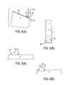
- FIG. 8(A) is a schematic side view of an embodiment of the invention assembled on a sloped shelf front
- FIG. 8(B) is a top view of an embodiment of the invention on a narrow shelf region
- FIGS. 9 (A) and 9 (B) are cross-sectional side views of embodiments of the invention wherein the holder member is integrated into the shelf structure;
- FIG. 9(C) is a cross-sectional side view of another embodiment wherein the holder member is integrated into the shelf structure;
- FIG. 9(D) is a cross-sectional perspective view of another embodiment wherein the shelf is adapted to include a holder member therein;
- FIGS. 9 (E) through 9 (G) are cross-sectional side views of various holder members that can be used in various embodiments of the invention.
- FIG. 9(H) is a cross-sectional side view of another embodiment wherein the shelf is adapted to include a holder member therein;
- FIG. 9(I) is a top view of the shelf of the embodiment shown in FIG. 9(H);
- FIG. 9(J) is a top perspective view of a tab portion of the shelf shown in FIG. 9(H).
- FIGS. 10 (A), 10 (B) and 10 (C) are cross-sectional side views of modified retaining wall members having various label holding means.
- FIG. 1(A) shows a first preferred embodiment of the invention
- FIGS. 1 (B) through 2 (D) show alternative embodiments having similarities to the embodiment shown in FIG. 1(A).
- the holder member 100 preferably has a label holder 110 and a generally horizontal portion 120 that extends rearwardly from the label holder 110 .
- the label holder 110 preferably has means for holding a label to display product information.
- the label holder 110 includes a channel 111 for containing a label L, such as a card or the like.
- a label L such as a card or the like.
- other forms of label holders can be provided.
- the label holder 110 can include a generally flat surface for fixing labels thereto via adhesives or the like.
- the label holder 110 can also include means for holding another label holder element, such as the element 300 shown in FIGS. 3 (A), 3 (B) and 3 (D).
- the label holder 110 can be modified to include other structural configurations for mounting a label or a label holding element. As shown in FIG. 3(C), the label holder 110 can also be omitted, such as when no label is desired.
- the horizontal portion 120 preferably has a generally horizontal lower surface 121 for placement upon a shelf S and an upper surface 122 having means for attaching the front retaining wall member 200 .
- the retaining wall member 200 preferably has a generally horizontal base or floor 220 and a retaining wall 210 extending upward from the floor 220 .
- the floor 220 is preferably generally flat.
- the shape of the floor 220 can be varied, but the floor 220 preferably has multiple points of contact (two or more) against the holder member 100 (e.g., proximate a front end and a rear end of the floor 220 ) for enhanced stability.
- the retaining wall 210 is preferably transparent or clear to facilitate viewing of product on the shelf S. However, it can also be opaque, and it can also include labels, printing, or label holding means such as a channel thereon.
- the wall 210 is also preferably generally flat and vertical. However, the shape and orientation can be modified as desired.
- the retaining wall 210 can be formed at an obtuse angle or at an acute angle to the floor 220 .
- an acute angle may be desired when the shelf S slopes downward toward the front of the shelf, such as shown in FIG. 8(A).
- the retaining wall 210 preferably extends upward from the floor 220 at or near a front end 222 of the floor 220 .
- the retaining wall 210 can be closer to the front of the shelf S to increase the area for products on the shelf.
- the wall 210 can extend up from the floor 220 at any location between the rear end and the front end of the floor 220 .
- a user initially attaches a holder member 100 on a shelf S.
- the holder member 100 can be attached to the shelf S by nails, screws, bolts, adhesives or the like.
- the holder member 100 can be permanently, semi-permanently or releasably attached to the shelf.
- the portion 120 preferably includes holes or slots 125 for receiving bolts, screws or the like connectors for attachment to the shelf S.
- a retaining wall member 200 can be attached by hand for example. Although less preferred, the retaining wall member 200 can be attached to the holder member 100 prior to attaching the member 100 to the shelf.
- the member 200 is preferably attached to the member 100 manually without the need for additional tools, such as nails or the like.
- the members 100 and 200 are snap-fit together, while the base 220 enhances the stability of the structure.
- the front and rear sides of the base 220 are restrained to further enhance stability.
- the front and rear ends of the member 200 may be snap-fit, for example, to the member 100 .
- one of the front and rear ends includes an engagement formed by an overhanging member that inhibits movement of the member 200 to increase stability.
- the member 100 preferably includes: a) a first means for applying a blocking force F 1 to block (i.e., inhibit) forward motion of the second plastic strip; b) a second means for applying a downward blocking force F 2 at a rear end of the generally horizontal portion of the second strip; and c) third means for applying an upward blocking force F 3 at a front end of the generally horizontal portion of the second strip.
- FIG. 1(A) shows a first preferred embodiment of the invention.
- the second means includes an overhanging member 130 that extends over a rear end 221 of the floor 220 when attached.
- the first means includes an upward protrusion 140 that extends in front of the front end 222 of the floor 220 when attached.
- the upper surface 122 acts as the third means preventing such downward movement.
- the retaining wall member 200 can be attached to the holder member 100 by sliding the rear end 221 of the floor 220 under the overhanging member 130 and lowering the floor 220 to a position in between the upward protrusion 140 and the overhanging member 130 .
- the forward portion 131 of the overhanging member 130 can prevent the member 200 from rotating in a counter-clockwise direction CCW. That is, the portion 131 overlaps the rear end 221 to prevent the rear end 221 from moving upward.
- the upward protrusion 140 prevents the member 200 from moving forward to ensure that the overhanging member 130 remains in a proper blocking position.
- the overhanging member 130 preferably extends over the rear end 221 a sufficient distance to prevent the member 200 from being rotated, without breaking or deforming the member 200 and/or the overhanging member 130 .
- the overhanging member preferably does not merely provide a “snap-fit” securing force, but a stronger force based on the strength of the materials to resist fracture or structural deformation.
- the wall 210 can preferably resist a substantial force acting in the counter-clockwise direction CCW. As a result, e.g., products retained on the shelf can press against the wall 210 without causing the wall 210 to pivot counter-clockwise, and the wall 210 can easily resist a customer's inadvertent contact with the wall 210 when removing products from the shelf S.
- Some exemplary preferred embodiments of the invention can withstand a force F 5 , FIG. 4, applied at about 1 to 5 inches above the floor 220 , of about 3 lbs., or even about 5 lbs., or even about 7 lbs., or even about 9 lbs., or even about 11 lbs. or more per linear foot.
- the force F 5 capable of being withstood can vary significantly depending on circumstances.
- a snap-fit connection is also included.
- the upward protrusion 140 preferably has a rearward bulge portion 141 that snap-fits over a front bulge portion 223 of the floor 220 .
- the member 200 can be very securely attached to the holder member 100 .
- This “snap-fit” engagement will provide a fourth force means that creates a fourth force F 4 to further resist rotation in a clockwise direction CW (the overhanging member 130 and/or the surface 122 proximate thereto can also be configured to provide a degree of resistance to clockwise movement).
- the member 200 can be easily, quickly and securely attached by sliding the end 221 under the overhanging member 130 and snap-fitting the end 222 to the protrusion 141 .
- the present invention can, thus, provide a very stable structure that requires no additional parts and that can easily be attached by hand.
- the member 200 can be rotated in a clockwise direction CW (disengaging the snap-fit connection, when used) and the rear end 221 can be pulled out from under the overhanging member 130 . Then, if desired, a new member 200 can be attached in a similar manner to that discussed above. If desired, the member 200 can also be omitted.
- the portions 130 and 140 can be constructed relatively small to avoid interference with products on the shelf S over substantially the entire upper surface 122 . Accordingly, when the member 200 is not needed, or not desired, it can be removed without limiting the operability or the appearance of the shelf S.
- FIG. 1(B) shows another embodiment of the invention wherein the first means for applying a blocking force F 1 to block forward motion of the second plastic strip is modified to include an upward protrusion 140 ′ having a cross-section with an outer bulge 141 ′ that snap-fits into a flexible channel 223 ′ on the member 200 .
- the snap-fit engagement in this embodiment both prevents forward movement and provides a force F 4 resisting clockwise movement.
- FIG. 1(B) also illustrates a second member 200 ′ having an alternative construction of the channel, e.g., channel 223 ′′ (it is contemplated that the snap-fit engagement can be formed in a variety of ways as should be understood by those in the art based on this disclosure).
- FIG. 1(C) shows another manner of snap-fitting the members together.
- the member 200 has a protrusion 230 similar to the protrusion 140 ′ of FIG. 1(B) and the member 100 has a slot 150 for snap-fitting the protrusion 230 .
- the slot 150 can be modified to be similar to the channel 223 ′ shown in FIG. 1(B), e.g., extending upward from the surface 122 .
- FIG. 1(D) shows another embodiment wherein the label holder 110 is used as the first means for applying a blocking force F 1 to block forward movement of the second plastic strip.
- This embodiment can also include means to provide a snap-fit, such as a bulge 141 ′′ that functions like the bulge 141 to snap-fit with the portion 223 of the member 200 .
- the rearward end 221 of the member 200 is secured by an overhanging member 130 and the forward end 222 of the member 200 is, in the preferred constructions, snap-fit to the member 100 .
- any known snap-fit configuration can be used to provide such a snap-fit between the members 100 and 200 .
- the snap-fit connection is most preferably proximate the front of the member 200 as shown (e.g., for increased stability, etc.), the snap-fit location can be moved further towards the rear end of the floor 220 towards the overhanging member 130 .
- the member 200 can also have a widened base 250 at the connection to the floor 220 to increase the strength of the connection.
- a widened base 250 can also be used in the other embodiments of the invention.
- FIGS. 2 (A) illustrates another, although less preferred, embodiment of the invention wherein the rear end 221 of the member 200 is modified to include a forwardly extending hook 260 and wherein the overhanging member 130 ′ is modified to extend over a lower portion 261 of the hook.
- the member 130 ′ can provide both the first force F 1 and the second force F 2 .
- the front end 222 is still preferably snap-fit (e.g., at a region R) to the member 100 in a manner similar to that in the various embodiments discussed above or similar to that shown in FIG. 2(B).
- the device is at least constructed so that front end 222 contacts the surface 122 to enhance stability and provide the third force F 3 .
- FIG. 2(B) illustrates an embodiment that is similar to the embodiment shown in FIG. 2(A) wherein the upper surface 122 is at a raised elevation such that the horizontal portion 120 is thicker and the overhanging portion 130 ′′ is formed by creating a cavity in the portion 120 .
- this embodiment requires an increased amount of material for the portion 120 and is, thus, less preferred.
- the embodiments shown in FIGS. 1 (A)- 1 (D) can be similarly modified to have a overhanging portion 130 formed within a similar cavity; if required, the end 221 could include a downward step to fit into such a cavity and under the overhanging portion.
- the front end 222 is also preferably snap-fit at a region R.
- FIG. 2(B) also illustrates that the snap-fit connection can include, as one example, an forward lower bulge r 1 and a rearward upper bulge r 2 .
- the floor 220 can be, in essence, in tension under such a snap-fit.
- FIGS. 2 (C) and 2 (D) illustrate additional, although less preferred, embodiments of the invention.
- the member 200 includes a floor or base 220 having an upward extension 225 .
- the member 100 has an upward protrusion 140 ′′ and an overhanging member 130 ′ having an overhanging wall 131 and a downwardly extending wall 132 .
- the overhanging member 130 ′ is formed integrally with the label holder 110 , but the overhanging member 130 ′ can also be formed separate from the label holder 110 .
- the portion 225 can be fit under the overhanging member 130 ′ and the end 221 of the floor 220 can be blocked by, or preferably snap-fit to, the protrusion 140 ′′.
- FIG. 2(C) illustrates one of the less preferred embodiments wherein an overhanging member is proximate a front side and a snap-fit member is proximate a rear side (i.e., reversed from the embodiments shown in FIGS. 1 (A)- 1 (D) and 2 (A)- 2 (B)).
- the embodiment shown in FIG. 2(C) can be reversed (i.e., the attachment of the base 220 to the portion 120 can be reversed) so as to be oriented like that in FIGS. 1 (A) through 2 (B), and vise-verse.
- An orientation as shown in FIGS. 1 (A) through 2 (B) is preferred, however, for resisting counterclockwise CCW movement.
- FIG. 2(D) illustrates an embodiment that is similar to that shown in FIG. 2(B), but reversed in orientation.
- a rearwardly facing hook 260 engages an overhanging member 130 ′′ that is formed with a generally T-shape cross-section.
- An opposite end of the floor 220 has a snap-fit member R 1 that snap-fits over an end R 2 of the overhanging member 130 ′′.
- the portion 261 can be fit under the overhanging member 130 ′′ and the portion R 1 can be snap-fit to the portion R 2 .
- the arrangement could also be reversed to be oriented like that shown in FIGS. 1 (A) through 2 (B).
- FIGS. 3 (A), 3 (B) and 3 (D) illustrate embodiments of the label holder 110 having an additional label holder element 300 connected thereto.
- the additional label holder element 300 preferably includes a plurality of channels 310 for receiving labels, such as cards.
- the label holder element 300 includes rear snap-in legs 320 for securement within a channel of the label holder 110 .
- FIG. 3(A) the label holder element 300 includes rear snap-in legs 320 for securement within a channel of the label holder 110 .
- the label holder 110 is a flat wall that is received within a rear channel 330 of the portion 300 .
- the labeling can be modified to accommodate a desired display type for different products or the like.
- the element 300 can also be constructed to have different numbers of channels and/or to have other label holder configurations.
- FIG. 3(D) is a cross-sectional side view of another embodiment of the invention having an alternative label holder 110 .
- the label holder includes a bead section which snap-fits into a channel 330 ′ of the element 300 .
- the bead section can also include a cut-away slot 110 S to enhance flexure of the holder 110 to facilitate connection.
- FIGS. 3 (E), 3 (F) and 3 (G) illustrate other embodiments of the invention wherein the label holder 110 is configured to allow a label to be placed at a plurality of inclination angles.
- a user can select a desired inclination angle of a label to facilitate viewing, such as from above or below the elevation of the label.
- a separate label holder element 300 can be connected to the member 100 at a desired angular position.
- the configuration of the label holder element 300 can be varied as desired.
- the label holder element 300 has two channels, but one or more channels can be used.
- the label holder 110 includes a connecting element that cooperates with a connecting element on the label holder element 300 to connect the label holder element at a desired angular position. It is contemplated that the connecting elements can be any known connectors for adjusting an angular position.
- the attachment is a snap-fit attachment or an interlocking attachment that does not require external parts, such as screws, pins, or the like.
- the connecting elements are preferably co-extruded therewith.
- the connecting element A of the label holder 110 includes a plurality of grooves 110 g while the connecting element B of the label holder element 300 includes one or more projections for engaging said grooves.
- the connecting element B of the element 300 is generally C-shaped, has a plurality of inner projections, and is flexible to allow the projections to snap-fit into the grooves 110 g.
- four positions of the element 300 are available. It should be understood, however, that alternative embodiments can have more or less positions.
- the connecting element A can be replaced with a connecting element having a different configuration as long as it can engage a corresponding connecting element B of the label holder 110 .
- the label holder element 300 can have two engaging projections for engaging two such grooves, or in another example just a single engaging projection can be used.
- the member B could be held in place via friction and compression forces without any interlocking projections.
- the label holder element 300 can be asymmetrical such that it can provide a different angular position merely by mounting it in an inverted position on the holder 110 .
- FIG. 3(F) shows another exemplary embodiment wherein the label holder 110 has a generally bowed shape and a central ridge R.
- the holder element 300 includes rear projections that can either engage a bottom of the ridge R and a top of the holder (as shown), or a top of the ridge R and a bottom of the holder to provide two mounting positions of the holder element.
- FIG. 3(G) shows another embodiment wherein the label holder 110 is bowed to have a plurality of angular positions for labels thereon.
- the label holder 110 is bowed to have a plurality of angular positions for labels thereon.
- two or more channels can be used to hold labels L for viewing from different positions.
- the holder member 100 can be formed without a label holder.
- FIG. 3(C) shows a cross-sectional side view of another embodiment of the invention without a label holder.
- a label holder could be entirely omitted
- a label holder of a shelf S could be used (see, e.g., channel SC in FIG. 1(A))
- a label holder could be attached to the member 200 (see, e.g., portion 111 ′ in FIG. 5 and FIGS. 10 (A)- 10 (C) (discussed below)), etc.
- FIGS. 10 (A)- 10 (C) illustrate exemplary embodiments wherein the member 200 is provided with one or more label holder.
- the label holders can include one or more channels C on the front and/or back sides of the member 200 .
- the embodiments shown in FIGS. 10 (A)- 10 (C) are exemplary and a variety of other designs, sizes, arrangements and numbers of label holders or channels could be used.
- the member 200 includes channels on the back of the member 200 (i.e., facing the rear of the shelf), the member is preferably clear or transparent to enable viewing through the member 200 .
- FIGS. 10 (A)- 10 (C) illustrate exemplary embodiments wherein the member 200 is provided with one or more label holder.
- the label holders can include one or more channels C on the front and/or back sides of the member 200 .
- the embodiments shown in FIGS. 10 (A)- 10 (C) are exemplary and a variety of other designs, sizes, arrangements and numbers of label holders or channels could be used.
- 10 (A)- 10 (C) show label holders integrally formed with the member 200 (preferably by extrusion), it is contemplated that separate label holder elements (not shown) similar to the label holder elements 300 of the various embodiments described herein could be similarly connected to the member 200 , if desired.
- the members 100 and 200 are preferably formed of a plastic material. Most preferably, the plastic material is extruded to form the members 100 and 200 . However, the members can be injection molded, vacuum formed, or formed in other known ways. Alternatively, one or both of the members could be made from composite materials, aluminum (preferably, an extruded aluminum), roll formed metals (e.g., sheet metal), or from other suitable materials.
- the members 100 and 200 can be made with one or more of the following plastics: polycarbonate, butyrate, propionate, acetate, acrylic, acrylic DR, styrene, PVC, PVC acrylic, as well as with any other suitable plastics.
- the member 100 is preferably clear or transparent so that product on the shelf can be viewed therethrough.
- the member 200 is formed so that the width W of the base or floor 220 is less than about 3-5 inches, more preferably between about 1 ⁇ 4 to 2 inches, and even more preferably between about 1 ⁇ 2 and 1 inch. It is contemplated, however, that these sizes can vary significantly depending on circumstances.
- the width W of the floor 220 is preferably sized to provide sufficient stability while still minimizing rearward extension into the product containing area of the shelf.
- the member 100 can be sized, for example, so that the portion 120 has a length sufficient to support the member 200 on the shelf. Typically, the length will be a matter of inches.
- the portion 120 can also extend across the entire shelf floor to provide a consistent and smooth sliding surface (see, e.g., FIG. 8(B)).
- the thicknesses of the members 100 and 200 are in a range of about 0.04 to 0.125 inches. It is again contemplated, however, that these sizes can be varied greatly depending on circumstances.
- the height H of the wall 210 is between about 1 ⁇ 2 inch to 6 inches.
- the members can have heights H, for example, throughout a range of between about 1 ⁇ 2 inch to 6 inches.
- the members 100 and 200 can have a length sufficient to extend across a substantial portion of a shelf front in a store, or across an entire shelf front.
- the members 100 and 200 can have a length of between about 2-5 or between about 2-10 feet long.
- the members 100 and 200 can be relatively short so as to fit across a narrow shelf region.
- the members can be made to span only a few inches (such as, for example only, less than about 6 inches) so as to support a single row of items C there-behind.
- the items C can be, for example, soft drink cans or other items, and can be, for example, supported on an angled shelf as shown in FIG. 8(A).
- the portion 110 can be at a variety of positions with respect to the portion 120 .
- the angle can be about 90 degrees, as shown, or it can be varied to facilitate viewing by a customer depending on shelf location.
- the portions 300 can also be modified to provide a desired angle.
- the embodiments described above can also be modified to have the overhanging members 130 , 130 ′, 130 ′′ snap-fit to the member 200 .
- the end 221 can include a bulge that is snapped beneath the overhanging member 130 , as shown in FIG. 6.
- the overhanging members, e.g., 130 , etc. could be constructed to create a wedge-fit wherein the end 221 is wedged therein.
- the portion 131 can have an angled surface 132 to provide a wedging action as the end 221 is pushed thereunder.
- These snap-fit and wedge engagements can also provide a means for applying a force F 1 to resist forward motion of the second plastic strip (i.e., this can be an additional means or the only means for applying the force F 1 ).
- the locations of the overhanging members, e.g., 130 , etc., and the snap-fit or blocking portions can be reversed with one another, such that the overhanging member, e.g., 130 , etc., overhangs over the front end 222 of the floor and the snap-fit or blocking action is at or near the rear end 221 .
- the wall portion 210 would be located at a distance behind the end 222 at least sufficient to allow the overhanging member, e.g., 130 , etc., to engage the floor 220 .
- This type of embodiment can be used, for example, where there is a greater concern that the wall 210 will be forced to move in a clockwise direction, rather than in a counterclockwise direction.
- snap-fit connection can be made at both the front end 222 and the rear end 221 , without any overhanging member.
- this alternative is less preferred.
- a single snap-fit connection can be formed along the bottom of the base 220 , while the base can be used to stabilize without additional restraint (i.e., additional restraint via a snap-fit or overhanging connection) at one or both of the front and rear ends 222 and 221 .
- vertical partitions can be included which extend perpendicular to both the wall 210 and the portion 120 .
- the partitions can, for example, be snap-fit to the portion 120 , to the floor 220 , and/or to the wall 210 .
- the partitions can be constructed, e.g., similar to the shelf dividers shown in U.S. Pat. No. 5,341,945 (see dividers 12), the disclosure of which is incorporated herein by reference.
- the present invention is preferably provided as a kit having a plurality of different retaining wall members 200 that are each attachable to the same holder member 100 .
- a plurality of retaining wall members 200 ( 1 )- 200 ( 5 ) having different wall heights H can be provided to enable the retaining wall height to be changed as desired.
- five members 200 are shown, the number of different members 200 can be varied.
- different retaining wall members 200 can be used to change to clear or to opaque wall members, or to change to wall members having label holders thereon (such as the channel 111 ′ shown in FIG. 5, etc.), or to change to wall members having printing or the like thereon.
- FIGS. 9 (A) and 9 (B) show shelves S with holder members 100 ′, 100 ′′ integrally formed therein.
- the embodiments shown in FIGS. 9 (A) and 9 (B) are similar to that shown in FIG. 1(A), with an upward protrusion 140 and an overhanging member 130 integrally formed in the shelf.
- the shelf S can be made of metal (e.g., sheet metal), plastic (e.g., injection molded, extruded, etc.), wood or any other suitable material. In one preferred embodiment, however, the shelf S is made from a roll formed sheet metal material. Most preferably, the shelf is constructed such that the top surface of the shelf is formed from a single sheet of material that is bent (e.g., via known roll forming processes, etc.) so as to include the holder member portions integral therewith.
- metal e.g., sheet metal
- plastic e.g., injection molded, extruded, etc.
- wood any other suitable material.
- the shelf S is made from a roll formed sheet metal material.
- the shelf is constructed such that the top surface of the shelf is formed from a single sheet of material that is bent (e.g., via known roll forming processes, etc.) so as to include the holder member portions integral therewith.
- FIG. 9(C) Another example of a shelf that is constructed to incorporate the structure of the holder member is shown in FIG. 9(C).
- the shelf is preferably formed of a sheet metal that is roll formed so as to include a holder member 100 ′′′ in the upper surface thereof.
- the sheet metal shelf can include a channel C integral with the shelf at the front end of the shelf as is known in the art.
- the member 200 ′ can be constructed to include a portion 200 H that extends laterally toward the front of the shelf and a label holder, such as a channel C, formed at the front of the member 200 ′.
- the member 200 ′ can extend upwards as shown in dashed lines in FIG.
- the member 200 ′ can include both a retaining wall and a front channel as shown or the member 200 ′ can be formed into a variety of other shapes, configurations, etc., known in the art or desired based on circumstances.
- FIG. 9(D) shows another embodiment of a prefabricated shelf S that is adapted to readily include a modified holder member.
- the shelf S preferably includes a groove or channel 100 B formed proximate the front side SF of the shelf.
- the channel 100 B can be formed such that the bottom of the channel extends all the way to the front side SF of the shelf.
- a holder member element 100 A is located within the channel 100 B.
- the holder member element is preferably formed with means (e.g., elements 130 , 140 or any other structure as described herein) for mounting another member, e.g., members 200 , 200 ′, 200 ′′ (FIG. 9(E)), as in other embodiments described herein.
- the channel 100 B can include a simplified structure (e.g., without overhanging portions) that can be easily formed into the shelf.
- a channel 100 B can be easily formed by punching (e.g., with a reciprocated punch press) into a flat sheet material to form the shelf.
- the channel 100 B can also be easily formed by bending the sheet material by simplified techniques (e.g., around forming blocks, etc.) other than more expensive and/or complex techniques using roll forming machines.
- the shelf S can be formed without an integral or attached front channel portion at the front end SF.
- shelf manufacture can be expensive and complex due to the need to include a front channel like that shown in FIG. 9(C) and as commonly included on store shelf fronts.
- the shelf structure S can be simplified, while maintaining versatility, etc.
- the depth d of the shelf S can be approximately between about 1 to 11 ⁇ 2 inches, the height h of the channel to the bottom thereof can be less than about 1 ⁇ 2 inch, or even less than about 1 ⁇ 3 inch, and the width w of the channel can be slightly larger than about the size of the widths W of the floor 220 described above. It should be understood that various sizes can be selected based on circumstances.
- the member 100 A is preferably constructed so as to accommodate a member 200 , 200 ′, or 200 ′′ (discussed below in relation to FIG. 9(E)), as in other embodiments described herein.
- the simplified shelf S can be readily adapted to include a vertical retaining wall and/or shelf front label(s) in an extremely versatile and adaptive manner.
- FIG. 9(E) shows another exemplary member 200 ′′ wherein the member includes a vertical wall and an upstanding retaining portion 200 A which is somewhat flexible or which includes flexible protrusions facing the retaining wall.
- the member 200 ′′ is preferably formed so as to mount on the member 100 A in a manner like that discussed above with reference to other embodiments disclosed herein.
- the flexible member 200 A is provided to allow the member 200 ′′ to mount an additional label holding member 200 B, such as shown in FIGS. 9 (F) or 9 (G).
- the member 200 B includes a rear insert extension 200 Bi that is configured to be press fit or snap fit to create a friction engagement between the member 200 A and the retaining wall of the member 200 ′′.
- the member 200 B is configured so that a label holding portion (e.g., a channel in the shown embodiment) can be located at a front end of the shelf, such as like that shown in FIG. 9(C).
- the member 200 B′ shown in FIG. 9(G) is similar to that shown in FIG.
- the member 200 B′ includes a second label holder, e.g., channel 2 C, mounted over the first label holder, e.g., channel C, via a flexible portion 200 Bf.
- product labeling for the consumer e.g., price, names, etc.
- labeling for business use e.g., bar codes, etc.
- the store owner can pivot the portion 2 C in the direction of the arrow shown to expose the channel C for inventory and other business purposes.
- a portion 200 A′ can be formed, if desired, on an interior—product side—of the retaining wall as shown in FIG. 9(E).
- the portion 200 A′ can be used to retain product dividers (i.e., dividers adapted with an insert similar to 200 Bi) in a manner generally similar to, for example, dividers 12 shown in U.S. Pat. No. 5,341,945, the entire disclosure of which is incorporated herein by reference.
- FIGS. 9 (H)- 9 (I) shown another embodiment of the invention that is similar to the embodiment shown in FIG. 9(D).
- the embodiment shown in FIG. 9(H) includes a different method of attaching the holder member element 100 A′ to the channel 100 B′.
- a plurality of upstanding tabs 100 T are preferably formed on a bottom of the channel along an axis A extending along the length of the channel.
- the tabs 100 T preferably have a generally T-shape as shown in FIG. 9(H) so as to form overhanging portions that can engage a bottom of the member 100 A′.
- the member 100 A′ is preferably formed with a bottom channel 100 AC that is adapted to engage with the top of the tabs 100 T.
- the width of the channel 100 AC is preferably narrower than the width of the top of the tabs 100 T.
- the channel 100 AC is preferably snap-fit to the tabs due to resiliency in the member 100 A′ adjacent the channel.
- the member can be rigid at the channel and can be attached by sliding the member 100 A′ laterally into the channel 100 B′ such that the tabs 100 T are received in the channel 100 AC from a side thereof.
- the shelf S can be formed of a sheet metal material.
- the channel 100 B′ can be formed therein as discussed above and the tabs 100 T can be formed by punching the sheet metal material upward from the bottom side of the shelf using known techniques.
- the tabs 100 T can be made as bent sections that are separated from a planar surface of the shelf at regions 100 S at opposite sides thereof. It should be understood that this is just one illustrative embodiment and that tabs can be formed in a variety of ways. As one other example, tabs could be added to the shelf as separate members. In addition, a single elongated tab member could extend along the length of the axis A (e.g., the tab could be roll formed, extruded, etc.).
- the members 200 ′, 200 ′′, 200 B, 200 B′, 100 A and 100 A′ shown in FIGS. 9 (C)- 9 (H) can be made in a manner similar to any of the members 100 and/or 200 described herein (see, e.g., the following section).
- the members are most preferably formed by extrusion. Most preferably, the members are made with extruded plastic. Alternatively, the members can be made with extruded aluminum or other appropriate materials, such as described herein. Alternatively, the members can be made with injection molding or other manufacturing methods. Any other methods of fabrication described herein or known to be appropriate to those in the art based on this disclosure can also be used.
- the members 100 A and 100 A′ are most preferably formed so as to fit entirely below a plain of the top surface of the shelf S when mounted within the channels 100 B and 100 B′, respectively.
- the members 100 A and 100 A′ could also be made, in less preferred embodiments to extend slightly above the top surface of the shelf. In less preferred embodiments, the members 100 A and 100 A′ may extend up to about 1 ⁇ 4 inch above the top of the shelf. In even less preferred embodiments, the members 100 A and 100 A′ may extend up to about 1 ⁇ 2 inch above the top of the shelf.
- the present invention is most preferably utilized with shelves having planar support top surfaces, which can be, for example, horizontal or, in some cases, tilted.
- the members 100 and 200 are most preferably formed by extruding a plastic material through an extrusion die and cutting appropriate section lengths during the extrusion process.
- the member 100 is preferably an integrally extruded single piece, and the member 200 is also preferably an integrally extruded single piece. That is, the members 100 and 200 are preferably solid pieces that are extruded through individual dies, rather than having two or more sections that are attached together.
- the members 100 and 200 can, thus, be formed with a generally constant and continuous cross-sectional shape.
- the cross-sections shown in the FIGS. are preferably generally constant and continuous over the entire lengths of these members. In this manner, the attachment means between the members 200 and the members 100 can attach the members together at any position along the lengths thereof.
- the present invention can be easily and inexpensively fabricated.
- the present invention can be constructed with a limited amount of material.
- the present invention also can have a minimal size to prevent obstruction and/or interference with normal shelf use. Nevertheless, the assembled device can be very strong and stable to provide a strong and stable shelf-front retaining wall.
- the present invention can be easily handled and manipulated.
- the store owner does not need to have additional parts or tools for assembly.
- the present invention enables a store owner to change the retaining wall type very easily.
- a store owner may often desire to rearrange products on shelves or to provide new products on shelves. Rearranging and/or organizing products on shelves can be very time consuming and difficult. Valuable time and money can be lost during such rearranging and/or organizing.
- the products can be damaged (e.g., if products fall from the shelves) and consumers can have difficulty locating products and can become dissatisfied with shopping under such conditions. It can be important to be able to quickly and easily rearrange and/or reorganize products as desired.
- a store owner can quickly attach a shelf-front wall as may be desired for a particular product type.
- a store owner can also have an employee change the assembly because no additional parts are needed and little or no instruction is needed.
- a front wall can be easily set at a desired height sufficient to retain products.
- shelf-front walls of various types can be used, such as clear, opaque, printed, etc. The rearrangement and/or reorganization of products is thus greatly facilitated.
Landscapes
- Physics & Mathematics (AREA)
- General Physics & Mathematics (AREA)
- Engineering & Computer Science (AREA)
- Theoretical Computer Science (AREA)
- Supports Or Holders For Household Use (AREA)
- Assembled Shelves (AREA)
Abstract
Description
- The present application is a continuation/divisional of and claims priority under 35 U.S.C. 120 to application Ser. No. 09/397,642, filed on Sep. 16, 1999, which in turn, claims priority to provisional application Ser. No. 60/100,630 filed on Sep. 16, 1998, the entire disclosures of which priority applications are both incorporated herein by reference as though recited herein in full.
- 1. Field of the Invention
- The present invention pertains to the organization of merchandise on shelves for retail, display, or the like. In particular, the present invention involves an improved shelf-front assembly for labeling and/or retaining products.
- More particularly, the preferred embodiments of the present invention involve a unique manner of combining both a) a label holder and b) a front product retaining wall. The most preferred embodiments of the present invention involve a novel means to quickly, easily and securely change both a) labels and b) front retaining walls on a shelf to accommodate different or new product types.
- 2. Background of the Invention
- There are a variety of existing label holders that are attachable to shelves for displaying product information, such as prices and other characteristics. For example, elongated channels for removably attaching labels, such as label cards that fit within the channels, are known.
- There are also existing front retaining walls that retain products on shelves. However, such front retaining walls typically require attachment to be made with tools and/or additional parts, such as nails, bolts or the like. When a retaining wall is not attached with tools and/or additional parts, the retaining wall can become flimsy and insecure and/or can require excess material or structure.
- Examples of existing devices are shown in the following U.S. Pat. Nos: 1) 2,640,288; 2) 4,775,058; 3) 4,896,779; 4) 5,341,945; 5) 5,419,066; and 6) 5,557,337, the entire disclosures of which are incorporated herein by reference.
- The '337 patent shows a positioning assembly for shelf placards and separators having a longitudinal blocking frame 30 and a placard holder 40. As illustrated, the device includes a transverse bottom plate 10 having a longitudinal slot that receives an inserting end 31 of the frame 30. Among other things, the apparatus is complicated and requires excess material to secure the blocking frame 30.
- The '288 patent shows a device in FIG. 2 wherein a price tag holder hangs on the edge of a shelf. The holder includes a tapered rear flange 20 that is attached to the shelf. As stated on
column 3 of the '288 patent, “thehead portion 18 is vertically slotted from the upper edge as at 19 to receive the lower edge of a card, sign or the like, which may designate the name, quality or other characteristics of the goods offered.” The patent indicates that the “sloping upper face 21 [of the flange 20] prevents articles from sliding off the shelf by vibration or the like even in the absence of a card in slot 19” but that “[s]uch card 23, however, increases the security of goods on the shelf.” Although the “card” may increase the security of the goods on the shelf, the card is not securely mounted thereto nor is the card disclosed as being constructed of a suitable material to serve as a product front retaining wall in various circumstances. - There continues to be a need for an improved system by which labels and/or front retaining walls can be securely, quickly and easily changed to accommodate different or new product types.
- The present invention solves the above and other problems and provides an improved system by which labels and front retaining walls can be securely, quickly and easily changed to accommodate different or new product types.
- According to a first aspect of the invention, a shelf-front assembly is provided which includes: a first plastic strip having a generally horizontal portion for placement on a shelf surface; a second plastic strip having 1) a generally horizontal floor and 2) an upward wall extending up from the generally horizontal floor; the first plastic strip being attachable on a shelf with the generally horizontal portion on a top surface of the shelf; the first plastic strip having a top snap-fit element running lengthwise along the first plastic strip and having an overhanging member running parallel to the top snap-fit element; the second plastic strip having a bottom snap-fit element running lengthwise along the generally horizontal floor and an end of the generally horizontal floor fittable under the overhanging member; the first plastic strip being attachable to the second plastic strip with the top and bottom snap-fit elements snap-fit together and with the overhanging member overhanging the end of the generally horizontal floor portion.
- According to another aspect of the invention, a shelf-front assembly is provided which includes: a first extruded plastic strip having 1) a label holder and 2) a generally horizontal portion extending rearward from the label holder; a second extruded plastic strip having 1) a generally horizontal floor and 2) an upward wall extending up from the generally horizontal floor; the generally horizontal portion of the first strip having integrally extruded front and rear mechanical engagement portions extending continuously along the entire length of the first strip for engaging the generally horizontal floor of the second strip at forward and rearward positions to attach the second strip to the first strip without external attaching means. Preferably, the generally horizontal floor has a width in a front to rear direction that is substantially greater than a corresponding width of the upward wall, such as (in one example) more than five times wider. Preferably, the generally horizontal floor and the upward wall are generally planar walls extending transverse to one another. The floor and upward walls, however, can have other configurations. Preferably, at least one of the engagement portions is a snap-fit element that snap-fits to the generally horizontal floor of the second plastic strip and at least one of the engagement portions is an overhanging member that overhangs an end of the generally horizontal floor of the second plastic strip.
- According to another aspect of the invention, a method of making a shelf-front assembly is provided which includes the steps of: extruding through a first extrusion die a first plastic strip having 1) a generally horizontal portion for placement on a shelf surface, 2) a label holder at one end of the generally horizontal portion, 3) a front-motion blocking element, and 4) an overhanging member extending along a top surface of the generally horizontal portion; cutting a length of the first plastic strip; extruding through a second extrusion die a second plastic strip having 1) a generally horizontal floor and 2) an upward wall extending up from the generally horizontal floor; cutting a length of the second plastic strip; attaching the length of the first plastic strip on a shelf top surface with the generally horizontal portion on the shelf top surface and the label holder member proximate a front side of the shelf; attaching the length of the second plastic strip on the first plastic strip by sliding one end of the generally horizontal floor under the overhanging member and laying the generally horizontal floor on the generally horizontal portion of the first strip with the front-motion blocking element in front of a retaining surface of the second strip to retain the length of the second strip in position on the length of the first strip.
- According to another aspect of the invention, a shelf-front assembly is provided that includes: a first strip having 1) a generally horizontal portion for placement on a shelf surface and 2) a label holder at a front end of the generally horizontal portion; a second strip having an upward wall extending upward from a widened base; the first strip being attachable on a shelf with the generally horizontal portion on a top surface of the shelf and the label holder proximate a front side of the shelf; the first strip having at least one engaging element running lengthwise along the entire top surface of the generally horizontal portion; the base of the second strip having at least one engaging element running lengthwise along the entire length of the second strip; the first strip being manually attachable to the second strip by manually engaging the engaging elements of the first and second strips. Preferably, the first and second strips are extruded plastic strips.
- According to another aspect of the invention, a shelf-front assembly is provided which includes: a first elongated strip having 1) a generally horizontal portion for placement on a shelf surface, 2) a label holder at one end of the generally horizontal portion, 3) an overhanging member extending lengthwise along a top surface of the generally horizontal portion, and 4) a front-motion blocking surface; a second elongated strip having 1) a generally horizontal floor and 2) an upward wall extending up from the generally horizontal floor; the first strip being attachable on a shelf top surface with the generally horizontal portion on the shelf top surface and the label holder proximate a front end of the shelf; the second strip being detachably connectable on the first strip by sliding one end of the generally horizontal floor under the overhanging member and laying the generally horizontal floor on the generally horizontal portion of the first strip with the front blocking surface extending in front of a retaining surface of the second strip to retain the second strip on the first strip.
- According to another aspect of the invention, a shelf-front assembly is provided which includes: a first strip having a generally horizontal portion for placement on a shelf surface; a second strip having an upward wall extending upward from a widened base; the first strip being attachable on a shelf with the generally horizontal portion on a top surface of the shelf; means integrally formed on both the first and second strips for manually engaging the widened base of the second strip directly on the generally horizontal portion of the first strip at a location over the top surface of the shelf.
- According to another aspect of the invention, a shelf-front assembly kit is provided which includes: a first strip having a generally horizontal portion for placement on a shelf; a second strip having 1) a generally horizontal floor and 2) an upward wall extending up from the generally horizontal floor and having a height H1; the first strip being attachable on a shelf with the generally horizontal portion on a top surface of the shelf; the first strip having at least one top manually engaging element running lengthwise along a length of the generally horizontal portion; the second strip having at least one bottom manual engaging element running lengthwise along a length of the generally horizontal floor; the first strip being manually attachable to the second strip by manually engaging the top and bottom engaging elements together; a modified second strip having 1) a generally horizontal floor and 2) an upward wall extending up from the generally horizontal floor and having a height H2 that is substantially greater than the height H1; the modified second strip having at least one bottom manual engaging element running lengthwise along a length of the generally horizontal floor of the modified second strip; the first strip also being manually attachable to the modified second strip by manually engaging the top engaging element of the first strip with the bottom engaging element of the modified second strip; whereby the first strip is attachable to a shelf and the second strip and the first strip are manually interchangeably attachable to said first strip to vary between the heights H1 and H2 as desired.
- Advantages of the Invention
- The present invention has substantial advantages and benefits over the existing art. The advantages discussed herein are not necessarily applicable to each and every aspect or embodiment.
- One advantage is that the present invention can be easily and inexpensively fabricated. The present invention can also be constructed with a limited amount of material. The present invention also can be minimized to prevent obstruction and/or interference with normal shelf use. Nevertheless, the assembled device can be very strong and stable to provide a strong and stable shelf-front retaining wall.
- The present invention can also be easily handled and manipulated. A store owner does not need to have additional parts or tools for assembly. The present invention enables a store owner to change the retaining wall type very easily as needed. During normal store operation, a store owner may often desire to rearrange products on shelves or to provide new products on shelves. Rearranging and/or reorganizing products on shelves can be very time consuming and difficult. Valuable time and money can be lost during such rearranging and/or reorganizing. When products are not well organized and/or accommodated on a shelf, the products can be damaged (e.g., if products fall off the shelves) and consumers can have difficulty locating products and can become dissatisfied with shopping under such conditions. Accordingly, it can be important to be able to quickly and easily rearrange and/or reorganize products as desired.
- With the preferred embodiments of the present invention, a store owner can quickly attach a shelf-front wall as may be desired for a particular product type. A store owner can also have an employee change the assembly as needed because no additional parts are needed and little or no instruction is needed. As a result, a front wall can be set at a desired height sufficient to retain products. In addition, if desired, shelf-front walls of various types can be used as desired, such as clear walls, opaque walls, printed walls, etc. The rearrangement and/or reorganization of products is thus greatly facilitated.
- The above and other advantages, features and aspects of the present invention will be more readily perceived from the following description of the preferred embodiments thereof taken together with the accompanying drawings and claims.
- The present invention is illustrated by way of example and not limitation in the accompanying drawings, in which like references indicate like parts, and in which:
- FIG. 1(A) is a perspective/cross-sectional view of a first embodiment of the invention;
- FIGS. 1(B) through 1(D) are each cross-sectional side views showing alternative embodiments of the invention;
- FIG. 2(A) through 2(D) are each cross-sectional side views showing other alternative embodiments of the invention;
- FIG. 3(A) is a cross-sectional side view of another embodiment of the invention having an additional label holder element;
- FIG. 3(B) is a cross-sectional side view of another embodiment of the invention having an alternative additional label holder element;
- FIG. 3(C) is a cross-sectional side view of another embodiment of the invention without a label holder element;
- FIG. 3(D) is a cross-sectional side view of another embodiment of the invention having an alternative label holder element;
- FIG. 3(E) is a cross-sectional side view of an embodiment of the invention having means for selecting a viewing angle of a label;
- FIG. 3(F) is a cross-sectional side view of another embodiment of the invention having means for selecting a viewing angle of a label;
- FIG. 3(G) is a cross-sectional side view of still another embodiment of the invention having means for selecting a viewing angle of a label;
- FIG. 4 is a schematic diagram illustrating restraining forces on a retaining wall element;
- FIG. 5 is a schematic diagram illustrating an assembly kit according to the invention having a plurality of interchangeable retaining wall elements;
- FIGS. 6 and 7 are cross-sectional side views of alternative manners of engagement between the retaining wall element and the overhanging member of the type, e.g., shown in FIG. 1(A);
- FIG. 8(A) is a schematic side view of an embodiment of the invention assembled on a sloped shelf front;
- FIG. 8(B) is a top view of an embodiment of the invention on a narrow shelf region;
- FIGS. 9(A) and 9(B) are cross-sectional side views of embodiments of the invention wherein the holder member is integrated into the shelf structure;
- FIG. 9(C) is a cross-sectional side view of another embodiment wherein the holder member is integrated into the shelf structure;
- FIG. 9(D) is a cross-sectional perspective view of another embodiment wherein the shelf is adapted to include a holder member therein;
- FIGS. 9(E) through 9(G) are cross-sectional side views of various holder members that can be used in various embodiments of the invention;
- FIG. 9(H) is a cross-sectional side view of another embodiment wherein the shelf is adapted to include a holder member therein;
- FIG. 9(I) is a top view of the shelf of the embodiment shown in FIG. 9(H);
- FIG. 9(J) is a top perspective view of a tab portion of the shelf shown in FIG. 9(H); and
- FIGS. 10(A), 10(B) and 10(C) are cross-sectional side views of modified retaining wall members having various label holding means.
- The preferred embodiments of the present invention include an assembly having a
holder member 100 and a frontretaining wall member 200. In the drawings, like reference numerals are used for similar parts. FIG. 1(A) shows a first preferred embodiment of the invention, and FIGS. 1(B) through 2(D) show alternative embodiments having similarities to the embodiment shown in FIG. 1(A). - Holder Member
- The
holder member 100 preferably has alabel holder 110 and a generallyhorizontal portion 120 that extends rearwardly from thelabel holder 110. - The
label holder 110 preferably has means for holding a label to display product information. In the most preferred embodiments, thelabel holder 110 includes achannel 111 for containing a label L, such as a card or the like. Alternatively, although less preferred, other forms of label holders can be provided. As one example, a placard holder of the type shown in U.S. Pat. No. 5,577,337—the disclosure of which is incorporated herein by reference—can be used (see, e.g., element 40 in the '337 patent). As another example, thelabel holder 110 can include a generally flat surface for fixing labels thereto via adhesives or the like. As discussed below, thelabel holder 110 can also include means for holding another label holder element, such as theelement 300 shown in FIGS. 3(A), 3(B) and 3(D). In addition, thelabel holder 110 can be modified to include other structural configurations for mounting a label or a label holding element. As shown in FIG. 3(C), thelabel holder 110 can also be omitted, such as when no label is desired. - The
horizontal portion 120 preferably has a generally horizontallower surface 121 for placement upon a shelf S and anupper surface 122 having means for attaching the frontretaining wall member 200. - Retaining Wall Member
- The
retaining wall member 200 preferably has a generally horizontal base orfloor 220 and aretaining wall 210 extending upward from thefloor 220. Thefloor 220 is preferably generally flat. The shape of thefloor 220 can be varied, but thefloor 220 preferably has multiple points of contact (two or more) against the holder member 100 (e.g., proximate a front end and a rear end of the floor 220) for enhanced stability. The retainingwall 210 is preferably transparent or clear to facilitate viewing of product on the shelf S. However, it can also be opaque, and it can also include labels, printing, or label holding means such as a channel thereon. Thewall 210 is also preferably generally flat and vertical. However, the shape and orientation can be modified as desired. For example, depending on circumstances, the retainingwall 210 can be formed at an obtuse angle or at an acute angle to thefloor 220. As one example, an acute angle may be desired when the shelf S slopes downward toward the front of the shelf, such as shown in FIG. 8(A). - As shown in FIG. 1(A), for example, the retaining
wall 210 preferably extends upward from thefloor 220 at or near afront end 222 of thefloor 220. In this manner, when attached to theholder member 100, the retainingwall 210 can be closer to the front of the shelf S to increase the area for products on the shelf. Alternatively, thewall 210 can extend up from thefloor 220 at any location between the rear end and the front end of thefloor 220. - Attachment Method
- Preferably, a user initially attaches a
holder member 100 on a shelf S. Theholder member 100 can be attached to the shelf S by nails, screws, bolts, adhesives or the like. Theholder member 100 can be permanently, semi-permanently or releasably attached to the shelf. Theportion 120 preferably includes holes orslots 125 for receiving bolts, screws or the like connectors for attachment to the shelf S. - After attachment of the
holder member 100, a retainingwall member 200 can be attached by hand for example. Although less preferred, the retainingwall member 200 can be attached to theholder member 100 prior to attaching themember 100 to the shelf. - The
member 200 is preferably attached to themember 100 manually without the need for additional tools, such as nails or the like. Preferably, themembers base 220 enhances the stability of the structure. Most preferably, the front and rear sides of the base 220 are restrained to further enhance stability. The front and rear ends of themember 200 may be snap-fit, for example, to themember 100. Most Preferably, however, one of the front and rear ends includes an engagement formed by an overhanging member that inhibits movement of themember 200 to increase stability. - As discussed with reference to the more preferred embodiments below, as shown in FIG. 4, the
member 100 preferably includes: a) a first means for applying a blocking force F1 to block (i.e., inhibit) forward motion of the second plastic strip; b) a second means for applying a downward blocking force F2 at a rear end of the generally horizontal portion of the second strip; and c) third means for applying an upward blocking force F3 at a front end of the generally horizontal portion of the second strip. - A First Preferred Embodiment
- FIG. 1(A) shows a first preferred embodiment of the invention. In the embodiment shown in FIG. 1(A), the second means includes an overhanging
member 130 that extends over arear end 221 of thefloor 220 when attached. Preferably, the first means includes anupward protrusion 140 that extends in front of thefront end 222 of thefloor 220 when attached. In the embodiment shown in FIG. 1(A), theupper surface 122 acts as the third means preventing such downward movement. - In this manner, the retaining
wall member 200 can be attached to theholder member 100 by sliding therear end 221 of thefloor 220 under the overhangingmember 130 and lowering thefloor 220 to a position in between theupward protrusion 140 and the overhangingmember 130. As a result, theforward portion 131 of the overhangingmember 130 can prevent themember 200 from rotating in a counter-clockwise direction CCW. That is, theportion 131 overlaps therear end 221 to prevent therear end 221 from moving upward. Theupward protrusion 140 prevents themember 200 from moving forward to ensure that the overhangingmember 130 remains in a proper blocking position. The overhangingmember 130 preferably extends over the rear end 221 a sufficient distance to prevent themember 200 from being rotated, without breaking or deforming themember 200 and/or the overhangingmember 130. The overhanging member preferably does not merely provide a “snap-fit” securing force, but a stronger force based on the strength of the materials to resist fracture or structural deformation. Thewall 210 can preferably resist a substantial force acting in the counter-clockwise direction CCW. As a result, e.g., products retained on the shelf can press against thewall 210 without causing thewall 210 to pivot counter-clockwise, and thewall 210 can easily resist a customer's inadvertent contact with thewall 210 when removing products from the shelf S. Some exemplary preferred embodiments of the invention can withstand a force F5, FIG. 4, applied at about 1 to 5 inches above thefloor 220, of about 3 lbs., or even about 5 lbs., or even about 7 lbs., or even about 9 lbs., or even about 11 lbs. or more per linear foot. The force F5 capable of being withstood can vary significantly depending on circumstances. - In the most preferred embodiments, in addition to blocking forward motion, a snap-fit connection is also included. In this regard, in the embodiment shown in FIG. 1(A), the
upward protrusion 140 preferably has arearward bulge portion 141 that snap-fits over afront bulge portion 223 of thefloor 220. In this manner, themember 200 can be very securely attached to theholder member 100. This “snap-fit” engagement will provide a fourth force means that creates a fourth force F4 to further resist rotation in a clockwise direction CW (the overhangingmember 130 and/or thesurface 122 proximate thereto can also be configured to provide a degree of resistance to clockwise movement). - Thus, the
member 200 can be easily, quickly and securely attached by sliding theend 221 under the overhangingmember 130 and snap-fitting theend 222 to theprotrusion 141. For example, one can grasp thewall 210 and push theend 222 downward and/or one can use one's finger(s) F to press thefloor 220 down to snap the members together. The present invention can, thus, provide a very stable structure that requires no additional parts and that can easily be attached by hand. - In order to remove the
retaining wall member 200, themember 200 can be rotated in a clockwise direction CW (disengaging the snap-fit connection, when used) and therear end 221 can be pulled out from under the overhangingmember 130. Then, if desired, anew member 200 can be attached in a similar manner to that discussed above. If desired, themember 200 can also be omitted. Theportions upper surface 122. Accordingly, when themember 200 is not needed, or not desired, it can be removed without limiting the operability or the appearance of the shelf S. - Additional Embodiments
- FIG. 1(B) shows another embodiment of the invention wherein the first means for applying a blocking force F 1 to block forward motion of the second plastic strip is modified to include an
upward protrusion 140′ having a cross-section with anouter bulge 141′ that snap-fits into aflexible channel 223′ on themember 200. As with the snap-fit embodiment shown in FIG. 1(A), the snap-fit engagement in this embodiment both prevents forward movement and provides a force F4 resisting clockwise movement. FIG. 1(B) also illustrates asecond member 200′ having an alternative construction of the channel, e.g.,channel 223″ (it is contemplated that the snap-fit engagement can be formed in a variety of ways as should be understood by those in the art based on this disclosure). - FIG. 1(C) shows another manner of snap-fitting the members together. In this embodiment, the
member 200 has aprotrusion 230 similar to theprotrusion 140′ of FIG. 1(B) and themember 100 has aslot 150 for snap-fitting theprotrusion 230. In another alternative, theslot 150 can be modified to be similar to thechannel 223′ shown in FIG. 1(B), e.g., extending upward from thesurface 122. - FIG. 1(D) shows another embodiment wherein the
label holder 110 is used as the first means for applying a blocking force F1 to block forward movement of the second plastic strip. This embodiment can also include means to provide a snap-fit, such as abulge 141″ that functions like thebulge 141 to snap-fit with theportion 223 of themember 200. - In each of the above-noted preferred embodiments, the
rearward end 221 of themember 200 is secured by an overhangingmember 130 and theforward end 222 of themember 200 is, in the preferred constructions, snap-fit to themember 100. It is contemplated that any known snap-fit configuration can be used to provide such a snap-fit between themembers member 200 as shown (e.g., for increased stability, etc.), the snap-fit location can be moved further towards the rear end of thefloor 220 towards the overhangingmember 130. - As shown in dashed lines in FIG. 1(C), the
member 200 can also have a widenedbase 250 at the connection to thefloor 220 to increase the strength of the connection. A widenedbase 250 can also be used in the other embodiments of the invention. - FIGS. 2(A) illustrates another, although less preferred, embodiment of the invention wherein the
rear end 221 of themember 200 is modified to include a forwardly extendinghook 260 and wherein the overhangingmember 130′ is modified to extend over alower portion 261 of the hook. In this embodiment, themember 130′ can provide both the first force F1 and the second force F2. Nevertheless, to enhance stability of thewall 210, thefront end 222 is still preferably snap-fit (e.g., at a region R) to themember 100 in a manner similar to that in the various embodiments discussed above or similar to that shown in FIG. 2(B). Preferably, the device is at least constructed so thatfront end 222 contacts thesurface 122 to enhance stability and provide the third force F3. - FIG. 2(B) illustrates an embodiment that is similar to the embodiment shown in FIG. 2(A) wherein the
upper surface 122 is at a raised elevation such that thehorizontal portion 120 is thicker and the overhangingportion 130″ is formed by creating a cavity in theportion 120. However, this embodiment requires an increased amount of material for theportion 120 and is, thus, less preferred. Although also less preferred, it is also contemplated that the embodiments shown in FIGS. 1(A)-1(D) can be similarly modified to have a overhangingportion 130 formed within a similar cavity; if required, theend 221 could include a downward step to fit into such a cavity and under the overhanging portion. - As shown in FIG. 2(B), the
front end 222 is also preferably snap-fit at a region R. FIG. 2(B) also illustrates that the snap-fit connection can include, as one example, an forward lower bulge r1 and a rearward upper bulge r2. Thefloor 220 can be, in essence, in tension under such a snap-fit. - FIGS. 2(C) and 2(D) illustrate additional, although less preferred, embodiments of the invention. In the embodiment shown in FIG. 2(C), the
member 200 includes a floor orbase 220 having anupward extension 225. On the other hand, themember 100 has anupward protrusion 140″ and an overhangingmember 130′ having an overhangingwall 131 and a downwardly extendingwall 132. In the illustrated embodiment, the overhangingmember 130′ is formed integrally with thelabel holder 110, but the overhangingmember 130′ can also be formed separate from thelabel holder 110. In operation, theportion 225 can be fit under the overhangingmember 130′ and theend 221 of thefloor 220 can be blocked by, or preferably snap-fit to, theprotrusion 140″. - FIG. 2(C) illustrates one of the less preferred embodiments wherein an overhanging member is proximate a front side and a snap-fit member is proximate a rear side (i.e., reversed from the embodiments shown in FIGS. 1(A)-1(D) and 2(A)-2(B)). In other variations, the embodiment shown in FIG. 2(C) can be reversed (i.e., the attachment of the base 220 to the
portion 120 can be reversed) so as to be oriented like that in FIGS. 1(A) through 2(B), and vise-verse. An orientation as shown in FIGS. 1(A) through 2(B) is preferred, however, for resisting counterclockwise CCW movement. - FIG. 2(D) illustrates an embodiment that is similar to that shown in FIG. 2(B), but reversed in orientation. As shown, a rearwardly facing
hook 260 engages an overhangingmember 130″ that is formed with a generally T-shape cross-section. An opposite end of thefloor 220 has a snap-fit member R1 that snap-fits over an end R2 of the overhangingmember 130″. In operation, theportion 261 can be fit under the overhangingmember 130″ and the portion R1 can be snap-fit to the portion R2. As with the other embodiments, it should be understood that the arrangement could also be reversed to be oriented like that shown in FIGS. 1(A) through 2(B). - FIGS. 3(A), 3(B) and 3(D) illustrate embodiments of the
label holder 110 having an additionallabel holder element 300 connected thereto. Although not shown, these embodiments can include any of the attachment methods disclosed herein for mounting amember 200 thereto. The additionallabel holder element 300 preferably includes a plurality ofchannels 310 for receiving labels, such as cards. In the embodiments shown in FIGS. 3(A) and 3(B), two channels are included. However, the number can be varied as desired. In the embodiment shown in FIG. 3(A), thelabel holder element 300 includes rear snap-inlegs 320 for securement within a channel of thelabel holder 110. In the embodiment shown in FIG. 3(B), thelabel holder 110 is a flat wall that is received within arear channel 330 of theportion 300. In this manner, the labeling can be modified to accommodate a desired display type for different products or the like. Theelement 300 can also be constructed to have different numbers of channels and/or to have other label holder configurations. - FIG. 3(D) is a cross-sectional side view of another embodiment of the invention having an
alternative label holder 110. As shown, the label holder includes a bead section which snap-fits into achannel 330′ of theelement 300. The bead section can also include a cut-away slot 110S to enhance flexure of theholder 110 to facilitate connection. - FIGS. 3(E), 3(F) and 3(G) illustrate other embodiments of the invention wherein the
label holder 110 is configured to allow a label to be placed at a plurality of inclination angles. In these embodiments, a user can select a desired inclination angle of a label to facilitate viewing, such as from above or below the elevation of the label. - In the embodiments shown in FIGS. 3(E) and 3(F), a separate
label holder element 300 can be connected to themember 100 at a desired angular position. In these embodiments, the configuration of thelabel holder element 300 can be varied as desired. In the example shown in FIG. 3(E), for example, thelabel holder element 300 has two channels, but one or more channels can be used. In these embodiments, thelabel holder 110 includes a connecting element that cooperates with a connecting element on thelabel holder element 300 to connect the label holder element at a desired angular position. It is contemplated that the connecting elements can be any known connectors for adjusting an angular position. Most preferably, the attachment is a snap-fit attachment or an interlocking attachment that does not require external parts, such as screws, pins, or the like. In the preferred embodiments where thelabel holder element 300 and themember 100 are formed by extrusion, such by extruding plastic or aluminum, the connecting elements are preferably co-extruded therewith. - In the exemplary preferred embodiment shown in FIG. 3(E), the connecting element A of the
label holder 110 includes a plurality of grooves 110 g while the connecting element B of thelabel holder element 300 includes one or more projections for engaging said grooves. Preferably, the connecting element B of theelement 300 is generally C-shaped, has a plurality of inner projections, and is flexible to allow the projections to snap-fit into the grooves 110 g. In the particular construction shown in FIG. 3(E), four positions of theelement 300 are available. It should be understood, however, that alternative embodiments can have more or less positions. - Alternatively, the connecting element A can be replaced with a connecting element having a different configuration as long as it can engage a corresponding connecting element B of the
label holder 110. For example, thelabel holder element 300 can have two engaging projections for engaging two such grooves, or in another example just a single engaging projection can be used. Alternatively, the member B could be held in place via friction and compression forces without any interlocking projections. In another alternative embodiment (not shown), thelabel holder element 300 can be asymmetrical such that it can provide a different angular position merely by mounting it in an inverted position on theholder 110. - FIG. 3(F) shows another exemplary embodiment wherein the
label holder 110 has a generally bowed shape and a central ridge R. Theholder element 300 includes rear projections that can either engage a bottom of the ridge R and a top of the holder (as shown), or a top of the ridge R and a bottom of the holder to provide two mounting positions of the holder element. - FIG. 3(G) shows another embodiment wherein the
label holder 110 is bowed to have a plurality of angular positions for labels thereon. For example, two or more channels (two are shown) can be used to hold labels L for viewing from different positions. - As discussed, although less preferred, the
holder member 100 can be formed without a label holder. As one example, FIG. 3(C) shows a cross-sectional side view of another embodiment of the invention without a label holder. In this regard, (a) a label holder could be entirely omitted, (b) a label holder of a shelf S could be used (see, e.g., channel SC in FIG. 1(A)), (c) a label holder could be attached to the member 200 (see, e.g.,portion 111′ in FIG. 5 and FIGS. 10(A)-10(C) (discussed below)), etc. - FIGS. 10(A)-10(C) illustrate exemplary embodiments wherein the
member 200 is provided with one or more label holder. As shown, the label holders can include one or more channels C on the front and/or back sides of themember 200. The embodiments shown in FIGS. 10(A)-10(C) are exemplary and a variety of other designs, sizes, arrangements and numbers of label holders or channels could be used. When themember 200 includes channels on the back of the member 200 (i.e., facing the rear of the shelf), the member is preferably clear or transparent to enable viewing through themember 200. Although FIGS. 10(A)-10(C) show label holders integrally formed with the member 200 (preferably by extrusion), it is contemplated that separate label holder elements (not shown) similar to thelabel holder elements 300 of the various embodiments described herein could be similarly connected to themember 200, if desired. - Preferred Construction
- The
members members - As some non-limiting examples, the
members member 100 is preferably clear or transparent so that product on the shelf can be viewed therethrough. - In preferred embodiments, the
member 200 is formed so that the width W of the base orfloor 220 is less than about 3-5 inches, more preferably between about ¼ to 2 inches, and even more preferably between about ½ and 1 inch. It is contemplated, however, that these sizes can vary significantly depending on circumstances. The width W of thefloor 220 is preferably sized to provide sufficient stability while still minimizing rearward extension into the product containing area of the shelf. - The
member 100 can be sized, for example, so that theportion 120 has a length sufficient to support themember 200 on the shelf. Typically, the length will be a matter of inches. Theportion 120 can also extend across the entire shelf floor to provide a consistent and smooth sliding surface (see, e.g., FIG. 8(B)). - In one exemplary embodiment, the thicknesses of the
members - In one exemplary construction, the height H of the
wall 210 is between about ½ inch to 6 inches. When a plurality of different members are provided, the members can have heights H, for example, throughout a range of between about ½ inch to 6 inches. - In one exemplary embodiment, the
members members - In another exemplary embodiment, the
members - Additional Modifications
- Although the
members 100 are illustrated as being generally T-shaped, theportion 110 can be at a variety of positions with respect to theportion 120. For example, the angle can be about 90 degrees, as shown, or it can be varied to facilitate viewing by a customer depending on shelf location. As discussed above, theportions 300 can also be modified to provide a desired angle. - The embodiments described above can also be modified to have the overhanging
members member 200. In the embodiment shown in FIG. 1(A), for example, theend 221 can include a bulge that is snapped beneath the overhangingmember 130, as shown in FIG. 6. As another alternative, the overhanging members, e.g., 130, etc., could be constructed to create a wedge-fit wherein theend 221 is wedged therein. As shown in FIG. 7, for example, theportion 131 can have anangled surface 132 to provide a wedging action as theend 221 is pushed thereunder. These snap-fit and wedge engagements can also provide a means for applying a force F1 to resist forward motion of the second plastic strip (i.e., this can be an additional means or the only means for applying the force F1). - Although much less preferred, as discussed above, it is contemplated that the locations of the overhanging members, e.g., 130, etc., and the snap-fit or blocking portions can be reversed with one another, such that the overhanging member, e.g., 130, etc., overhangs over the
front end 222 of the floor and the snap-fit or blocking action is at or near therear end 221. Thewall portion 210 would be located at a distance behind theend 222 at least sufficient to allow the overhanging member, e.g., 130, etc., to engage thefloor 220. This type of embodiment can be used, for example, where there is a greater concern that thewall 210 will be forced to move in a clockwise direction, rather than in a counterclockwise direction. - In less preferred embodiments, snap-fit connection can be made at both the
front end 222 and therear end 221, without any overhanging member. For enhanced stability, however, this alternative is less preferred. Even less preferred, a single snap-fit connection can be formed along the bottom of thebase 220, while the base can be used to stabilize without additional restraint (i.e., additional restraint via a snap-fit or overhanging connection) at one or both of the front andrear ends - If desired, vertical partitions (not shown) can be included which extend perpendicular to both the
wall 210 and theportion 120. The partitions can, for example, be snap-fit to theportion 120, to thefloor 220, and/or to thewall 210. The partitions can be constructed, e.g., similar to the shelf dividers shown in U.S. Pat. No. 5,341,945 (see dividers 12), the disclosure of which is incorporated herein by reference. - Assembly Kit
- The present invention is preferably provided as a kit having a plurality of different
retaining wall members 200 that are each attachable to thesame holder member 100. For example, as shown in FIG. 5, a plurality of retaining wall members 200(1)-200(5) having different wall heights H can be provided to enable the retaining wall height to be changed as desired. Although fivemembers 200 are shown, the number ofdifferent members 200 can be varied. In addition, differentretaining wall members 200 can be used to change to clear or to opaque wall members, or to change to wall members having label holders thereon (such as thechannel 111′ shown in FIG. 5, etc.), or to change to wall members having printing or the like thereon. - Integrated with Shelf
- In an alternative construction of any of the embodiments disclosed herein, a shelf can be constructed to incorporate the structure of the
holder member 100. As some examples, FIGS. 9(A) and 9(B) show shelves S withholder members 100′, 100″ integrally formed therein. The embodiments shown in FIGS. 9(A) and 9(B) are similar to that shown in FIG. 1(A), with anupward protrusion 140 and an overhangingmember 130 integrally formed in the shelf. - The shelf S can be made of metal (e.g., sheet metal), plastic (e.g., injection molded, extruded, etc.), wood or any other suitable material. In one preferred embodiment, however, the shelf S is made from a roll formed sheet metal material. Most preferably, the shelf is constructed such that the top surface of the shelf is formed from a single sheet of material that is bent (e.g., via known roll forming processes, etc.) so as to include the holder member portions integral therewith.
- Another example of a shelf that is constructed to incorporate the structure of the holder member is shown in FIG. 9(C). In this embodiment, the shelf is preferably formed of a sheet metal that is roll formed so as to include a
holder member 100′′′ in the upper surface thereof. As shown, the sheet metal shelf can include a channel C integral with the shelf at the front end of the shelf as is known in the art. In the illustrated embodiment, themember 200′ can be constructed to include aportion 200H that extends laterally toward the front of the shelf and a label holder, such as a channel C, formed at the front of themember 200′. Alternatively, themember 200′ can extend upwards as shown in dashed lines in FIG. 9(C) so as to form a retaining wall similar to that described above in other embodiments. Alternatively, themember 200′ can include both a retaining wall and a front channel as shown or themember 200′ can be formed into a variety of other shapes, configurations, etc., known in the art or desired based on circumstances. - FIG. 9(D) shows another embodiment of a prefabricated shelf S that is adapted to readily include a modified holder member. As shown, the shelf S preferably includes a groove or
channel 100B formed proximate the front side SF of the shelf. In less preferred embodiments (not shown), thechannel 100B can be formed such that the bottom of the channel extends all the way to the front side SF of the shelf. As shown, aholder member element 100A is located within thechannel 100B. The holder member element is preferably formed with means (e.g.,elements members - The
element 100A can be mounted within thechannel 100B in a variety of ways. For example, anadhesive tape 100C (e.g., a foam tape, etc.) can be used, as shown. Alternatively, theelement 100A can be attached via adhesives, screws, rivets, bolts, clips, or any other known attachment means. - This latter embodiment has appreciable advantages in that, for example, the structure of the shelf S can be greatly simplified while easily being adapted to include various elements of the present invention to provide versatility, etc. Notably, the
channel 100B can include a simplified structure (e.g., without overhanging portions) that can be easily formed into the shelf. For instance, achannel 100B can be easily formed by punching (e.g., with a reciprocated punch press) into a flat sheet material to form the shelf. As another example, thechannel 100B can also be easily formed by bending the sheet material by simplified techniques (e.g., around forming blocks, etc.) other than more expensive and/or complex techniques using roll forming machines. - Furthermore, the shelf S can be formed without an integral or attached front channel portion at the front end SF. Typically, shelf manufacture can be expensive and complex due to the need to include a front channel like that shown in FIG. 9(C) and as commonly included on store shelf fronts. As a result, the shelf structure S can be simplified, while maintaining versatility, etc. These simplifications can have substantial benefits and cost savings in view of the great number of shelf fronts used in merchandizing stores world wide.
- In some non-limiting and exemplary constructions of the shelf S, the depth d of the shelf S can be approximately between about 1 to 1½ inches, the height h of the channel to the bottom thereof can be less than about ½ inch, or even less than about ⅓ inch, and the width w of the channel can be slightly larger than about the size of the widths W of the
floor 220 described above. It should be understood that various sizes can be selected based on circumstances. - The
member 100A is preferably constructed so as to accommodate amember - FIG. 9(E) shows another
exemplary member 200″ wherein the member includes a vertical wall and anupstanding retaining portion 200A which is somewhat flexible or which includes flexible protrusions facing the retaining wall. Themember 200″ is preferably formed so as to mount on themember 100A in a manner like that discussed above with reference to other embodiments disclosed herein. - The
flexible member 200A is provided to allow themember 200″ to mount an additionallabel holding member 200B, such as shown in FIGS. 9(F) or 9(G). In the embodiment shown in FIG. 9(F), themember 200B includes a rear insert extension 200Bi that is configured to be press fit or snap fit to create a friction engagement between themember 200A and the retaining wall of themember 200″. Themember 200B is configured so that a label holding portion (e.g., a channel in the shown embodiment) can be located at a front end of the shelf, such as like that shown in FIG. 9(C). Themember 200B′ shown in FIG. 9(G) is similar to that shown in FIG. 9(F) except that themember 200B′ includes a second label holder, e.g.,channel 2C, mounted over the first label holder, e.g., channel C, via a flexible portion 200Bf. In this manner, product labeling for the consumer (e.g., price, names, etc.) can be provided for normal display on thechannel 2C while labeling for business use (e.g., bar codes, etc.) can be provided on the channel C, whereby the store owner can pivot theportion 2C in the direction of the arrow shown to expose the channel C for inventory and other business purposes. - In one alternative embodiment, a
portion 200A′ can be formed, if desired, on an interior—product side—of the retaining wall as shown in FIG. 9(E). Theportion 200A′ can be used to retain product dividers (i.e., dividers adapted with an insert similar to 200Bi) in a manner generally similar to, for example, dividers 12 shown in U.S. Pat. No. 5,341,945, the entire disclosure of which is incorporated herein by reference. - FIGS. 9(H)-9(I) shown another embodiment of the invention that is similar to the embodiment shown in FIG. 9(D). However, the embodiment shown in FIG. 9(H) includes a different method of attaching the
holder member element 100A′ to thechannel 100B′. As shown, a plurality ofupstanding tabs 100T are preferably formed on a bottom of the channel along an axis A extending along the length of the channel. Thetabs 100T preferably have a generally T-shape as shown in FIG. 9(H) so as to form overhanging portions that can engage a bottom of themember 100A′. Specifically, themember 100A′ is preferably formed with a bottom channel 100AC that is adapted to engage with the top of thetabs 100T. That is, the width of the channel 100AC is preferably narrower than the width of the top of thetabs 100T. In order to form the attachment, the channel 100AC is preferably snap-fit to the tabs due to resiliency in themember 100A′ adjacent the channel. Alternatively, the member can be rigid at the channel and can be attached by sliding themember 100A′ laterally into thechannel 100B′ such that thetabs 100T are received in the channel 100AC from a side thereof. - In one exemplary construction, the shelf S can be formed of a sheet metal material. The
channel 100B′ can be formed therein as discussed above and thetabs 100T can be formed by punching the sheet metal material upward from the bottom side of the shelf using known techniques. As shown in FIG. 9(J), thetabs 100T can be made as bent sections that are separated from a planar surface of the shelf atregions 100S at opposite sides thereof. It should be understood that this is just one illustrative embodiment and that tabs can be formed in a variety of ways. As one other example, tabs could be added to the shelf as separate members. In addition, a single elongated tab member could extend along the length of the axis A (e.g., the tab could be roll formed, extruded, etc.). - The
members 200′, 200″, 200B, 200B′, 100A and 100A′ shown in FIGS. 9(C)-9(H) can be made in a manner similar to any of themembers 100 and/or 200 described herein (see, e.g., the following section). As indicated, the members are most preferably formed by extrusion. Most preferably, the members are made with extruded plastic. Alternatively, the members can be made with extruded aluminum or other appropriate materials, such as described herein. Alternatively, the members can be made with injection molding or other manufacturing methods. Any other methods of fabrication described herein or known to be appropriate to those in the art based on this disclosure can also be used. - It is noted that in the embodiments shown in FIGS. 9(D) and 9(H), the
members channels members members members shelf - Extruded Construction
- As discussed above, the
members member 100 is preferably an integrally extruded single piece, and themember 200 is also preferably an integrally extruded single piece. That is, themembers members - Whether formed by extrusion or by other means (e.g., injection molding, machining, etc.), the cross-sections shown in the FIGS. are preferably generally constant and continuous over the entire lengths of these members. In this manner, the attachment means between the
members 200 and themembers 100 can attach the members together at any position along the lengths thereof. - Advantages and Benefits
- The present invention has substantial advantages and benefits over existing art. As should be appreciated, the advantages discussed herein are not necessarily applicable to each and every aspect or embodiment.
- As described above, the present invention can be easily and inexpensively fabricated. The present invention can be constructed with a limited amount of material. The present invention also can have a minimal size to prevent obstruction and/or interference with normal shelf use. Nevertheless, the assembled device can be very strong and stable to provide a strong and stable shelf-front retaining wall.
- The present invention can be easily handled and manipulated. The store owner does not need to have additional parts or tools for assembly. The present invention enables a store owner to change the retaining wall type very easily. During normal store operation, a store owner may often desire to rearrange products on shelves or to provide new products on shelves. Rearranging and/or organizing products on shelves can be very time consuming and difficult. Valuable time and money can be lost during such rearranging and/or organizing. When products are not well organized and/or accommodated on a shelf, the products can be damaged (e.g., if products fall from the shelves) and consumers can have difficulty locating products and can become dissatisfied with shopping under such conditions. It can be important to be able to quickly and easily rearrange and/or reorganize products as desired.
- With the preferred embodiments of the present invention, a store owner can quickly attach a shelf-front wall as may be desired for a particular product type. A store owner can also have an employee change the assembly because no additional parts are needed and little or no instruction is needed. As a result, a front wall can be easily set at a desired height sufficient to retain products. In addition, shelf-front walls of various types can be used, such as clear, opaque, printed, etc. The rearrangement and/or reorganization of products is thus greatly facilitated.
- In addition, embodiments like that shown in FIGS. 1(B) and 1(C)—wherein the snap-fit engagement is effected by a socket and plug type connection—can be beneficial when the width W of the
floor 220 varies slightly, such as due to inconsistencies resulting in an extrusion process. That is, the overhangingmember 130 can extend a large enough distance over theend 221 to allow a gap to exist between theend 221 and the vertical portion of themember 130. As a result, any dimensional variation in the width W resulting during formation, such as during extrusion thereof, should not inhibit connection. - While the present invention has been shown and described with reference to preferred embodiments presently contemplated as best modes for carrying out the invention, it is to be understood that various changes may be made in adapting the invention to different embodiments without departing from the broader inventive concepts disclosed herein and comprehended by the claims which follow. It is also to be understood that features from the various embodiments can be incorporated into and/or interchanged with features of other embodiments herein where appropriate.
Claims (14)
Priority Applications (1)
| Application Number | Priority Date | Filing Date | Title |
|---|---|---|---|
| US10/449,413 US6796445B2 (en) | 1998-09-16 | 2003-06-02 | Shelf-front assembly for labeling and retaining products |
Applications Claiming Priority (3)
| Application Number | Priority Date | Filing Date | Title |
|---|---|---|---|
| US10063098P | 1998-09-16 | 1998-09-16 | |
| US09/397,642 US6571498B1 (en) | 1998-09-16 | 1999-09-16 | Shelf-front assembly for labeling and retaining products |
| US10/449,413 US6796445B2 (en) | 1998-09-16 | 2003-06-02 | Shelf-front assembly for labeling and retaining products |
Related Parent Applications (1)
| Application Number | Title | Priority Date | Filing Date |
|---|---|---|---|
| US09/397,642 Division US6571498B1 (en) | 1998-09-16 | 1999-09-16 | Shelf-front assembly for labeling and retaining products |
Publications (2)
| Publication Number | Publication Date |
|---|---|
| US20030196979A1 true US20030196979A1 (en) | 2003-10-23 |
| US6796445B2 US6796445B2 (en) | 2004-09-28 |
Family
ID=26797383
Family Applications (2)
| Application Number | Title | Priority Date | Filing Date |
|---|---|---|---|
| US09/397,642 Expired - Fee Related US6571498B1 (en) | 1998-09-16 | 1999-09-16 | Shelf-front assembly for labeling and retaining products |
| US10/449,413 Expired - Fee Related US6796445B2 (en) | 1998-09-16 | 2003-06-02 | Shelf-front assembly for labeling and retaining products |
Family Applications Before (1)
| Application Number | Title | Priority Date | Filing Date |
|---|---|---|---|
| US09/397,642 Expired - Fee Related US6571498B1 (en) | 1998-09-16 | 1999-09-16 | Shelf-front assembly for labeling and retaining products |
Country Status (1)
| Country | Link |
|---|---|
| US (2) | US6571498B1 (en) |
Cited By (3)
| Publication number | Priority date | Publication date | Assignee | Title |
|---|---|---|---|---|
| US7159352B1 (en) | 2003-03-11 | 2007-01-09 | Daniel Lefebvre | End cap apparatus |
| US7841155B2 (en) | 2007-10-13 | 2010-11-30 | Mediseal Gmbh | Tool for a bag forming machine |
| US20130270205A1 (en) * | 2010-12-29 | 2013-10-17 | Big Skies Limited | Apparatus For Facing Products |
Families Citing this family (100)
| Publication number | Priority date | Publication date | Assignee | Title |
|---|---|---|---|---|
| US6571498B1 (en) * | 1998-09-16 | 2003-06-03 | Issac Cyrluk | Shelf-front assembly for labeling and retaining products |
| US20050189310A1 (en) * | 2001-04-26 | 2005-09-01 | Dci Marketing, Inc. | Merchandising system |
| AU2002258996A1 (en) * | 2001-04-26 | 2002-11-11 | Dci Marketing, Inc. | Merchandising system |
| US7124898B2 (en) * | 2001-04-26 | 2006-10-24 | Dci Marketing, Inc. | Merchandising system |
| US6886699B2 (en) | 2001-10-15 | 2005-05-03 | Dci Marketing, Inc. | Merchandising system |
| US20080011696A1 (en) * | 2001-04-26 | 2008-01-17 | Richter Gary M | Merchandising and product display system |
| US20030217980A1 (en) * | 2002-03-13 | 2003-11-27 | Johnson Allen E. | Merchandising system |
| WO2003105629A1 (en) * | 2002-06-01 | 2003-12-24 | Hancock Darras L J | Bench guard |
| US7168579B2 (en) | 2002-09-06 | 2007-01-30 | Dci Marketing, Inc. | Merchandising system |
| US6811044B2 (en) * | 2002-09-26 | 2004-11-02 | Brian Walker | Shelf liner |
| US6935061B2 (en) * | 2002-11-25 | 2005-08-30 | L&P Property Management Company | Tag holder assembly |
| EP1624779A4 (en) | 2003-05-22 | 2008-01-23 | Dci Marketing Inc | Merchandising system |
| US20070170133A1 (en) * | 2003-06-13 | 2007-07-26 | Dci Marketing, Inc. | Merchandising system |
| FR2861884B1 (en) * | 2003-10-31 | 2006-02-24 | Joalpe Ind De Expositores Sa | DISPLAY DEVICE, IN PARTICULAR FOR ELECTRONIC PRICE DISPLAY |
| US7225572B2 (en) * | 2004-02-27 | 2007-06-05 | Fast Industries, Ltd | Label/sign holder with J-strip support surface mount |
| US20050199565A1 (en) * | 2004-03-11 | 2005-09-15 | Dci Marketing, Inc. | Merchandising system |
| US20050199564A1 (en) * | 2004-03-11 | 2005-09-15 | Dci Marketing, Inc. | Merchandising system |
| US20050199563A1 (en) * | 2004-03-12 | 2005-09-15 | Richter Gary M. | Merchandising system |
| US7721659B2 (en) * | 2004-03-19 | 2010-05-25 | Fast Industries, Ltd. | Universal support element for universal shelf divider, label and sign holder |
| USD520776S1 (en) | 2004-10-06 | 2006-05-16 | Dci Marketing, Inc. | Merchandising system |
| US7395938B2 (en) * | 2005-02-18 | 2008-07-08 | Jo A. Merit | Method and apparatus for selective engagement of shelf divider structures within a shelf management system |
| US20060243683A1 (en) * | 2005-04-29 | 2006-11-02 | Onachilla Michael D | Merchandising display |
| US9060624B2 (en) | 2005-09-12 | 2015-06-23 | Rtc Industries, Inc. | Product management display system with rail mounting clip |
| US9750354B2 (en) | 2005-09-12 | 2017-09-05 | Rtc Industries, Inc. | Product management display system |
| US10285510B2 (en) | 2005-09-12 | 2019-05-14 | Rtc Industries, Inc. | Product management display system |
| US8453850B2 (en) | 2005-09-12 | 2013-06-04 | Rtc Industries, Inc. | Product management display system with trackless pusher mechanism |
| US11583109B2 (en) | 2005-09-12 | 2023-02-21 | Rtc Industries, Inc. | Product management display system with trackless pusher mechanism |
| US8863963B2 (en) | 2005-09-12 | 2014-10-21 | Rtc Industries, Inc. | Product management display system with trackless pusher mechanism |
| US10952546B2 (en) | 2005-09-12 | 2021-03-23 | Rtc Industries, Inc. | Product management display system with trackless pusher mechanism |
| US9232864B2 (en) | 2005-09-12 | 2016-01-12 | RTC Industries, Incorporated | Product management display system with trackless pusher mechanism |
| US9259102B2 (en) | 2005-09-12 | 2016-02-16 | RTC Industries, Incorporated | Product management display system with trackless pusher mechanism |
| US8978904B2 (en) | 2005-09-12 | 2015-03-17 | Rtc Industries, Inc. | Product management display system with trackless pusher mechanism |
| US8322544B2 (en) | 2005-09-12 | 2012-12-04 | Rtc Industries, Inc. | Product management display system with trackless pusher mechanism |
| US7823734B2 (en) | 2005-09-12 | 2010-11-02 | Rtc Industries, Inc. | Product management display system with trackless pusher mechanism |
| US8739984B2 (en) | 2005-09-12 | 2014-06-03 | Rtc Industries, Inc. | Product management display system with trackless pusher mechanism |
| US9265362B2 (en) | 2005-09-12 | 2016-02-23 | RTC Industries, Incorporated | Product management display system |
| US9265358B2 (en) | 2005-09-12 | 2016-02-23 | RTC Industries, Incorporated | Product management display system |
| US9486088B2 (en) | 2005-09-12 | 2016-11-08 | Rtc Industries, Inc. | Product management display system |
| US9138075B2 (en) | 2005-09-12 | 2015-09-22 | Rtc Industries, Inc. | Product management display system |
| US8312999B2 (en) | 2005-09-12 | 2012-11-20 | Rtc Industries, Inc. | Product management display system with trackless pusher mechanism |
| US8967394B2 (en) | 2005-09-12 | 2015-03-03 | Rtc Industries, Inc. | Product management display system with trackless pusher mechanism |
| US9173504B2 (en) | 2005-09-12 | 2015-11-03 | Rtc Industries, Inc. | Product management display system |
| US11259652B2 (en) | 2005-09-12 | 2022-03-01 | Rtc Industries, Inc. | Product management display system |
| US11344138B2 (en) | 2005-09-12 | 2022-05-31 | Rtc Industries, Inc. | Product management display system |
| US20070080126A1 (en) * | 2005-10-11 | 2007-04-12 | James Music | Slidable coupling components for shelf management systems |
| US20070090073A1 (en) * | 2005-10-26 | 2007-04-26 | The Stanley Works | System for displaying a sample of a product |
| US8579123B2 (en) * | 2006-02-16 | 2013-11-12 | Fasteners For Retail, Inc. | Merchandising system |
| US20070251905A1 (en) * | 2006-05-01 | 2007-11-01 | Frank Trotta | Shelving merchandising system |
| US20070272634A1 (en) * | 2006-05-23 | 2007-11-29 | Richter Gary M | Well Merchandiser |
| US20080016740A1 (en) * | 2006-06-30 | 2008-01-24 | Mitten J Patrick | Integrally Extruded Price Tag Molding and Front-End Stop Plate for Gravity-Feed Shelving |
| FR2904459B1 (en) * | 2006-07-27 | 2008-10-24 | Joalpe Ind De Expositores Sa | PROFILE LABEL HOLDER OR PROFILE HOLDER FOR FASTENING REMOVABLE LABEL HOLDER. |
| US7614350B2 (en) * | 2006-10-05 | 2009-11-10 | Haworth, Inc. | Wall-mounted shelf unit |
| US8622227B2 (en) | 2007-01-16 | 2014-01-07 | Fasteners For Retail, Inc. | Merchandise security system |
| WO2008088789A2 (en) * | 2007-01-16 | 2008-07-24 | Fasteners For Retail, Inc. | Merchandise security system |
| USD584941S1 (en) | 2007-02-09 | 2009-01-20 | Wilton Industries, Inc. | U-channel display bracket |
| US7591096B2 (en) * | 2007-07-10 | 2009-09-22 | Krinke Thomas A | Display holder |
| US7882969B2 (en) * | 2007-08-16 | 2011-02-08 | Lloyd, Gerstner & Partners | Display system with adjustable product holder track |
| US8020714B2 (en) * | 2007-10-31 | 2011-09-20 | Presence From Innovation, Llc | Product merchandising system for walk-in display coolers and the like |
| WO2009087606A1 (en) * | 2008-01-09 | 2009-07-16 | Gavin Milton Steer | Pricing management system |
| US7854333B2 (en) | 2008-05-07 | 2010-12-21 | Dci Marketing, Inc. | Rear loading gate for merchandising system |
| US8573134B2 (en) * | 2010-08-10 | 2013-11-05 | Michael Brenner | Transparent shelf guard |
| US8707599B2 (en) * | 2010-11-10 | 2014-04-29 | K-International, Inc. | Adjustable sign holder |
| US8616665B2 (en) * | 2011-05-24 | 2013-12-31 | Whirlpool Corporation | Door bin for a domestic refrigerator |
| US20120325763A1 (en) * | 2011-06-27 | 2012-12-27 | E-B Display Company, Inc. | Flip-down graphic shelf display and shelving unit incorporating the same |
| MX359912B (en) * | 2011-09-01 | 2018-10-16 | Milton Steer Gavin | Information display apparatus. |
| WO2013130395A1 (en) | 2012-02-27 | 2013-09-06 | Steelcase Development Corporation | Learning suite furniture system |
| USD704269S1 (en) | 2012-04-10 | 2014-05-06 | Target Brands, Inc. | Sign holder assembly |
| US9142150B2 (en) | 2012-04-10 | 2015-09-22 | Target Brands, Inc. | Sign holder assembly and associated method |
| US8752717B2 (en) * | 2012-04-12 | 2014-06-17 | Fasteners For Retail, Inc. | Base and divider assembly |
| US9149119B2 (en) | 2012-10-18 | 2015-10-06 | Customer Motivators, Llc | Ventilated shelf cover with spring clasp |
| US8871324B2 (en) | 2012-10-18 | 2014-10-28 | Customer Motivators, Llc | Ventilated shelf cover |
| US9259211B2 (en) | 2012-12-24 | 2016-02-16 | Transmed7, Llc | Automated, selectable, soft tissue excision biopsy devices and methods |
| US9677325B2 (en) * | 2013-02-14 | 2017-06-13 | Hyperkinetics Corporation | Bracket |
| US8925745B2 (en) * | 2013-03-06 | 2015-01-06 | Target Brands, Inc. | Shelf-type display module |
| US20140259830A1 (en) * | 2013-03-15 | 2014-09-18 | 3M Innovative Properties Company | Multi-panel sign systems and methods |
| USD801734S1 (en) | 2014-12-01 | 2017-11-07 | Retail Space Solutions Llc | Shelf management parts |
| US10154739B2 (en) | 2013-12-02 | 2018-12-18 | Retail Space Solutions Llc | Universal merchandiser and methods relating to same |
| US9245464B2 (en) | 2014-01-24 | 2016-01-26 | Target Brands, Inc. | Hook-type display module |
| US9681761B2 (en) * | 2014-04-08 | 2017-06-20 | Dongguan SAPP Products Ltd. | Simply structured rack |
| US9629483B2 (en) * | 2014-04-14 | 2017-04-25 | Fasteners For Retail, Inc. | Rail position lock |
| US9955802B2 (en) | 2015-04-08 | 2018-05-01 | Fasteners For Retail, Inc. | Divider with selectively securable track assembly |
| WO2017123988A1 (en) | 2016-01-13 | 2017-07-20 | Rtc Industries, Inc. | Merchandise display system with an anti-splay device |
| USD856715S1 (en) | 2016-06-29 | 2019-08-20 | Bruce Robins | Combined display tablet dock and table |
| BR102016019700B1 (en) * | 2016-08-25 | 2021-06-29 | Archi Comércio De Puxadores Ltda | PROFILE FOR A FURNITURE ARTICLE, PROFILE SYSTEM FOR A FURNITURE ARTICLE AND METHOD OF ASSEMBLING A FURNITURE ARTICLE |
| US10959540B2 (en) | 2016-12-05 | 2021-03-30 | Retail Space Solutions Llc | Shelf management system, components thereof, and related methods |
| US10470588B2 (en) | 2016-12-21 | 2019-11-12 | Walmart Apollo, Llc | Modular label track system |
| WO2018200997A1 (en) | 2017-04-27 | 2018-11-01 | Retail Space Solutions Llc | Shelf-mounted tray and methods relating to same |
| CN110996727B (en) | 2017-06-16 | 2021-08-31 | Rtc工业股份有限公司 | Product management display system with trackless pusher mechanism |
| US10905239B2 (en) | 2018-02-05 | 2021-02-02 | Gg Acquisition Company, Llc | Wall hanging garage shelf and rack storage system |
| US10750867B2 (en) * | 2018-02-05 | 2020-08-25 | Jared J. Newman | Wall hanging garage shelf and rack storage system |
| US10667629B2 (en) * | 2018-10-05 | 2020-06-02 | Fasteners For Retail, Inc. | Product pusher assembly |
| US20200214446A1 (en) * | 2019-01-08 | 2020-07-09 | Rodrigo Ceron | Decorative and strength enhancing assembly for wire shelving |
| IT201900003601A1 (en) * | 2019-03-12 | 2020-09-12 | Bortoluzzi Sistemi Spa | "ASSEMBLY SYSTEM AND METHOD FOR DRAWERS OR SHELVES" |
| US10765235B1 (en) * | 2019-07-23 | 2020-09-08 | Barry A. Awalt | Shelf cover with price tag holder |
| US10874228B1 (en) * | 2019-07-23 | 2020-12-29 | Barry A. Awalt | Shelf cover with price tag holder |
| US10765234B1 (en) * | 2019-07-23 | 2020-09-08 | Barry A. Awalt | Shelf cover with price tag holder |
| US10706749B1 (en) * | 2019-08-09 | 2020-07-07 | K-International, Inc. | Shelf label holder with breakaway guide and method |
| USD998231S1 (en) | 2021-08-24 | 2023-09-05 | B-O-F Corporation | Retail display indicia support with light channel |
| CN118382387A (en) * | 2021-12-06 | 2024-07-23 | 紧固件零售股份有限公司 | Product safety system |
| USD1051225S1 (en) | 2022-07-11 | 2024-11-12 | B-O-F Corporation | Shelf label holder |
Citations (27)
| Publication number | Priority date | Publication date | Assignee | Title |
|---|---|---|---|---|
| US2730825A (en) * | 1952-02-18 | 1956-01-17 | David L Wilds | Combination rack and price tagging device |
| US3308963A (en) * | 1965-05-12 | 1967-03-14 | Myers Ind Inc | Shelf edging and associated display structures |
| US3512652A (en) * | 1968-05-20 | 1970-05-19 | Armstrong Store Fixture Corp | Banding and binning means for display shelves |
| US4606280A (en) * | 1985-08-12 | 1986-08-19 | Brent Poulton | One piece shelf extender |
| US4613047A (en) * | 1985-03-25 | 1986-09-23 | Hallmark Cards, Incorporated | Small article display assembly |
| US4615276A (en) * | 1985-09-16 | 1986-10-07 | Garabedian Aram G | Shelf divider assembly |
| US4712694A (en) * | 1986-11-10 | 1987-12-15 | Rtc Industries, Inc. | Display shelf organizer |
| US4775058A (en) * | 1986-12-15 | 1988-10-04 | Jameson Pharmaceutical Corp. | Display shelf organizer |
| US4874099A (en) * | 1986-10-24 | 1989-10-17 | Ontario Limited | Napkin holder |
| US4896779A (en) * | 1987-08-14 | 1990-01-30 | L'oreal, S.A. | Display shelf organizer |
| US5255802A (en) * | 1991-03-22 | 1993-10-26 | Padco, Incorporated | Merchandise display system |
| US5326706A (en) * | 1989-07-17 | 1994-07-05 | Research Foundation Of State University Of New York | Homeostatic organ preservation system |
| US5341945A (en) * | 1993-08-31 | 1994-08-30 | Burke Gibson, Inc. | Shelf divider system |
| US5408775A (en) * | 1991-04-30 | 1995-04-25 | Vidpro International, Inc. | Merchandise information system |
| US5419066A (en) * | 1992-07-02 | 1995-05-30 | Logigraf Inc. | Card holder extrusion |
| US5577337A (en) * | 1995-06-29 | 1996-11-26 | Lin; Hsu K. | Positioning assembly for shelf placards and separators |
| US5577623A (en) * | 1993-02-11 | 1996-11-26 | L&P Property Management Company | Composite gravity feed shelf |
| US5673801A (en) * | 1996-03-25 | 1997-10-07 | Markson Rosenthal & Company | Shelf organizer display |
| US5682824A (en) * | 1996-01-29 | 1997-11-04 | Rtc Industries Inc. | Display shelf system |
| US5690038A (en) * | 1995-11-13 | 1997-11-25 | Merit; William | Method and apparatus for selective engagement of shelf separation structures |
| US5839588A (en) * | 1996-12-26 | 1998-11-24 | Hawkinson; Terry B. | Track system for feeding of product at points of sale |
| US6041720A (en) * | 1997-11-13 | 2000-03-28 | Rtc Industries, Inc. | Product management display system |
| US6047647A (en) * | 1999-02-05 | 2000-04-11 | Laraia, Jr.; Frank A. | Adjustable shelf assembly |
| US6226910B1 (en) * | 1999-06-07 | 2001-05-08 | Darko Company, Inc. | Merchandising shelf bracket |
| US6227385B1 (en) * | 1999-12-03 | 2001-05-08 | Dci Marketing, Inc. | Shelf tray system |
| US6299004B1 (en) * | 1999-12-10 | 2001-10-09 | Trion Industries, Inc. | Shelf organizing system |
| US6571498B1 (en) * | 1998-09-16 | 2003-06-03 | Issac Cyrluk | Shelf-front assembly for labeling and retaining products |
Family Cites Families (2)
| Publication number | Priority date | Publication date | Assignee | Title |
|---|---|---|---|---|
| US2640288A (en) | 1947-09-17 | 1953-06-02 | Orlin Max | Price tag holder |
| GB8404404D0 (en) | 1984-02-20 | 1984-03-28 | Kenney G H W | Ticket holders for shelving |
-
1999
- 1999-09-16 US US09/397,642 patent/US6571498B1/en not_active Expired - Fee Related
-
2003
- 2003-06-02 US US10/449,413 patent/US6796445B2/en not_active Expired - Fee Related
Patent Citations (29)
| Publication number | Priority date | Publication date | Assignee | Title |
|---|---|---|---|---|
| US2730825A (en) * | 1952-02-18 | 1956-01-17 | David L Wilds | Combination rack and price tagging device |
| US3308963A (en) * | 1965-05-12 | 1967-03-14 | Myers Ind Inc | Shelf edging and associated display structures |
| US3512652A (en) * | 1968-05-20 | 1970-05-19 | Armstrong Store Fixture Corp | Banding and binning means for display shelves |
| US4613047A (en) * | 1985-03-25 | 1986-09-23 | Hallmark Cards, Incorporated | Small article display assembly |
| US4606280A (en) * | 1985-08-12 | 1986-08-19 | Brent Poulton | One piece shelf extender |
| US4615276A (en) * | 1985-09-16 | 1986-10-07 | Garabedian Aram G | Shelf divider assembly |
| US4874099A (en) * | 1986-10-24 | 1989-10-17 | Ontario Limited | Napkin holder |
| US4712694A (en) * | 1986-11-10 | 1987-12-15 | Rtc Industries, Inc. | Display shelf organizer |
| US4775058A (en) * | 1986-12-15 | 1988-10-04 | Jameson Pharmaceutical Corp. | Display shelf organizer |
| US4896779A (en) * | 1987-08-14 | 1990-01-30 | L'oreal, S.A. | Display shelf organizer |
| US5326706A (en) * | 1989-07-17 | 1994-07-05 | Research Foundation Of State University Of New York | Homeostatic organ preservation system |
| US5255802A (en) * | 1991-03-22 | 1993-10-26 | Padco, Incorporated | Merchandise display system |
| US5408775A (en) * | 1991-04-30 | 1995-04-25 | Vidpro International, Inc. | Merchandise information system |
| US5419066A (en) * | 1992-07-02 | 1995-05-30 | Logigraf Inc. | Card holder extrusion |
| US5577623A (en) * | 1993-02-11 | 1996-11-26 | L&P Property Management Company | Composite gravity feed shelf |
| US5341945A (en) * | 1993-08-31 | 1994-08-30 | Burke Gibson, Inc. | Shelf divider system |
| US5577337A (en) * | 1995-06-29 | 1996-11-26 | Lin; Hsu K. | Positioning assembly for shelf placards and separators |
| US5690038B1 (en) * | 1995-11-13 | 2000-07-04 | William Merit | Method and apparatus for selective engagement of shelf separation structures |
| US5690038A (en) * | 1995-11-13 | 1997-11-25 | Merit; William | Method and apparatus for selective engagement of shelf separation structures |
| US6006678A (en) * | 1995-11-13 | 1999-12-28 | Merit; William | Method and apparatus for selective engagement of shelf separation structures conformed to provide visual display surfaces |
| US5682824A (en) * | 1996-01-29 | 1997-11-04 | Rtc Industries Inc. | Display shelf system |
| US5673801A (en) * | 1996-03-25 | 1997-10-07 | Markson Rosenthal & Company | Shelf organizer display |
| US5839588A (en) * | 1996-12-26 | 1998-11-24 | Hawkinson; Terry B. | Track system for feeding of product at points of sale |
| US6041720A (en) * | 1997-11-13 | 2000-03-28 | Rtc Industries, Inc. | Product management display system |
| US6571498B1 (en) * | 1998-09-16 | 2003-06-03 | Issac Cyrluk | Shelf-front assembly for labeling and retaining products |
| US6047647A (en) * | 1999-02-05 | 2000-04-11 | Laraia, Jr.; Frank A. | Adjustable shelf assembly |
| US6226910B1 (en) * | 1999-06-07 | 2001-05-08 | Darko Company, Inc. | Merchandising shelf bracket |
| US6227385B1 (en) * | 1999-12-03 | 2001-05-08 | Dci Marketing, Inc. | Shelf tray system |
| US6299004B1 (en) * | 1999-12-10 | 2001-10-09 | Trion Industries, Inc. | Shelf organizing system |
Cited By (4)
| Publication number | Priority date | Publication date | Assignee | Title |
|---|---|---|---|---|
| US7159352B1 (en) | 2003-03-11 | 2007-01-09 | Daniel Lefebvre | End cap apparatus |
| US7841155B2 (en) | 2007-10-13 | 2010-11-30 | Mediseal Gmbh | Tool for a bag forming machine |
| US20130270205A1 (en) * | 2010-12-29 | 2013-10-17 | Big Skies Limited | Apparatus For Facing Products |
| US9398817B2 (en) * | 2010-12-29 | 2016-07-26 | Big Skies Limited | Apparatus for facing products |
Also Published As
| Publication number | Publication date |
|---|---|
| US6796445B2 (en) | 2004-09-28 |
| US6571498B1 (en) | 2003-06-03 |
Similar Documents
| Publication | Publication Date | Title |
|---|---|---|
| US6796445B2 (en) | Shelf-front assembly for labeling and retaining products | |
| US6332547B1 (en) | Indexable gravity flow shelving system | |
| US6886700B2 (en) | Adjustable product display rack with extension panel | |
| US6409028B2 (en) | Shelf tray system | |
| CA2298218C (en) | Shelf organizing system | |
| US6305559B1 (en) | Product organizer | |
| US6006678A (en) | Method and apparatus for selective engagement of shelf separation structures conformed to provide visual display surfaces | |
| US6935060B2 (en) | Mounting system for label holders | |
| US4765492A (en) | Display assemblies for integrated modular store fixture system | |
| US6035569A (en) | Devices for mounting and display of electronic labels and the like | |
| US4705175A (en) | Display and pull-out tray assemblies for integrated modular store fixture system | |
| US4771898A (en) | Display and pull-out tray assemblies for integrated modular store fixture system | |
| US7201281B1 (en) | Adjustable modular merchandise pusher system | |
| US6581312B2 (en) | Adjustable sign mount with graphic | |
| MX2008007443A (en) | Label holder for merchandise display hooks and method of making same . | |
| US6898885B1 (en) | Label holder assembly with end sign | |
| US4532726A (en) | Ticket holders for shelving | |
| US5611512A (en) | Device for fixing an electronic display housing | |
| US7627971B2 (en) | Tapeless label holders for flat front face shelves | |
| US6581314B2 (en) | Label holder with selectively attachable sign holder | |
| US5996264A (en) | Sign holder for ticket moldings, strip form label carriers and the like | |
| US7308770B2 (en) | Electronic shelf label holder for scanner plate and wire supports | |
| WO1998032115A1 (en) | Devices for mounting and display of electronic labels and the like | |
| CA2377313C (en) | Indexable gravity flow shelving system | |
| US6178678B1 (en) | Menu board graphics display |
Legal Events
| Date | Code | Title | Description |
|---|---|---|---|
| FEPP | Fee payment procedure |
Free format text: PAYOR NUMBER ASSIGNED (ORIGINAL EVENT CODE: ASPN); ENTITY STATUS OF PATENT OWNER: SMALL ENTITY |
|
| FPAY | Fee payment |
Year of fee payment: 4 |
|
| AS | Assignment |
Owner name: CYRLUK, ISSAC, NEW JERSEY Free format text: ASSIGNMENT OF ASSIGNORS INTEREST;ASSIGNOR:INTEK PLASTICS, INC.;REEL/FRAME:026989/0644 Effective date: 20110602 |
|
| REMI | Maintenance fee reminder mailed | ||
| FPAY | Fee payment |
Year of fee payment: 8 |
|
| SULP | Surcharge for late payment |
Year of fee payment: 7 |
|
| REMI | Maintenance fee reminder mailed | ||
| LAPS | Lapse for failure to pay maintenance fees | ||
| STCH | Information on status: patent discontinuation |
Free format text: PATENT EXPIRED DUE TO NONPAYMENT OF MAINTENANCE FEES UNDER 37 CFR 1.362 |
|
| STCH | Information on status: patent discontinuation |
Free format text: PATENT EXPIRED DUE TO NONPAYMENT OF MAINTENANCE FEES UNDER 37 CFR 1.362 |
|
| FP | Lapsed due to failure to pay maintenance fee |
Effective date: 20160928 |