US20030196941A1 - Combined filter and skimmer assembly for pounds - Google Patents
Combined filter and skimmer assembly for pounds Download PDFInfo
- Publication number
- US20030196941A1 US20030196941A1 US10/128,625 US12862502A US2003196941A1 US 20030196941 A1 US20030196941 A1 US 20030196941A1 US 12862502 A US12862502 A US 12862502A US 2003196941 A1 US2003196941 A1 US 2003196941A1
- Authority
- US
- United States
- Prior art keywords
- skimmer
- filter
- assembly according
- combined filter
- skimmer assembly
- Prior art date
- Legal status (The legal status is an assumption and is not a legal conclusion. Google has not performed a legal analysis and makes no representation as to the accuracy of the status listed.)
- Granted
Links
- XLYOFNOQVPJJNP-UHFFFAOYSA-N water Substances O XLYOFNOQVPJJNP-UHFFFAOYSA-N 0.000 claims abstract description 55
- 238000007667 floating Methods 0.000 claims abstract description 24
- 230000008878 coupling Effects 0.000 claims abstract description 18
- 238000010168 coupling process Methods 0.000 claims abstract description 18
- 238000005859 coupling reaction Methods 0.000 claims abstract description 18
- 241000195493 Cryptophyta Species 0.000 description 6
- 241000251468 Actinopterygii Species 0.000 description 5
- 238000001914 filtration Methods 0.000 description 5
- 235000015097 nutrients Nutrition 0.000 description 5
- QGZKDVFQNNGYKY-UHFFFAOYSA-N Ammonia Chemical compound N QGZKDVFQNNGYKY-UHFFFAOYSA-N 0.000 description 4
- 239000000126 substance Substances 0.000 description 4
- 230000009182 swimming Effects 0.000 description 4
- 238000009412 basement excavation Methods 0.000 description 3
- XDDAORKBJWWYJS-UHFFFAOYSA-N glyphosate Chemical compound OC(=O)CNCP(O)(O)=O XDDAORKBJWWYJS-UHFFFAOYSA-N 0.000 description 3
- 238000012423 maintenance Methods 0.000 description 3
- 239000010802 sludge Substances 0.000 description 3
- 229910021529 ammonia Inorganic materials 0.000 description 2
- 238000005516 engineering process Methods 0.000 description 2
- BHEPBYXIRTUNPN-UHFFFAOYSA-N hydridophosphorus(.) (triplet) Chemical compound [PH] BHEPBYXIRTUNPN-UHFFFAOYSA-N 0.000 description 2
- 239000000463 material Substances 0.000 description 2
- 238000000034 method Methods 0.000 description 2
- 229920000728 polyester Polymers 0.000 description 2
- 241000269350 Anura Species 0.000 description 1
- 241000271566 Aves Species 0.000 description 1
- 241000255777 Lepidoptera Species 0.000 description 1
- 229920006328 Styrofoam Polymers 0.000 description 1
- 230000015572 biosynthetic process Effects 0.000 description 1
- 239000010872 fertilizer runoff Substances 0.000 description 1
- 239000012530 fluid Substances 0.000 description 1
- 238000005755 formation reaction Methods 0.000 description 1
- 238000009434 installation Methods 0.000 description 1
- 239000011159 matrix material Substances 0.000 description 1
- 238000012986 modification Methods 0.000 description 1
- 230000004048 modification Effects 0.000 description 1
- 229920000642 polymer Polymers 0.000 description 1
- 239000011435 rock Substances 0.000 description 1
- 239000007787 solid Substances 0.000 description 1
- 239000008261 styrofoam Substances 0.000 description 1
- 239000002699 waste material Substances 0.000 description 1
Images


Classifications
-
- A—HUMAN NECESSITIES
- A01—AGRICULTURE; FORESTRY; ANIMAL HUSBANDRY; HUNTING; TRAPPING; FISHING
- A01K—ANIMAL HUSBANDRY; AVICULTURE; APICULTURE; PISCICULTURE; FISHING; REARING OR BREEDING ANIMALS, NOT OTHERWISE PROVIDED FOR; NEW BREEDS OF ANIMALS
- A01K63/00—Receptacles for live fish, e.g. aquaria; Terraria
- A01K63/04—Arrangements for treating water specially adapted to receptacles for live fish
- A01K63/045—Filters for aquaria
Definitions
- the invention relates to outdoor ponds. More particularly, the invention relates to an apparatus for filtering pond water and skimming the surface of the pond.
- Ponds have always been a desirable landscaping feature, particularly in conjunction with gardens.
- artificial ponds have been relatively expensive to construct.
- fish-safe polymer liner material that can be formed into any convenient shape, and covered with rock strata, natural looking artificial ponds have become a popular landscape feature.
- An additional maintenance problem involves the removal of leaves and other foliage which fall onto the surface of the pond. Unless it is soon removed from the surface, this foliage settles to the bottom where it decompose forming a layer of sludge.
- the sludge may reduce the depth of the pond and may also cover underwater formations. Removing the sludge requires draining the pond, a drastic procedure which requires temporary storage of fish and threatens the life of aquatic plants.
- the applicant herein has looked beyond swimming pool technology to provide the Pondmaster® filter system.
- the applicant's Pondmaster® filter system is fully submersible in an existing pond, does not require any excavation, and does not require unsightly apparatus to be located adjacent to the pond. It is modular and can be expanded to suit ponds of different sizes. However, the Pondmaster® system does not include a skimmer.
- the apparatus of the present invention includes a submersible filter box containing replaceable filter media, the filter box having a water inlet, a skimmer coupling, and a water outlet adapted to be coupled to an underwater pump.
- the filter box is rectangular with a removable lid.
- the filter media is located in two sections of the box defined by two rows of baffles which are spaced apart to define a channel between the two sections.
- the water outlet is preferably aligned with the channel.
- the lid has a raised central portion wherein lies the water inlet.
- the water inlet is preferably adjustable as to the size of the inlet.
- the skimmer coupling is also located in the raised portion of the lid and is spaced apart from the water inlet.
- the skimmer coupling is coupled to an upstanding conduit, the end of which is coupled to a skimmer head.
- the skimmer head preferably includes a floating cup which automatically adjusts to the level of the surface of the pond.
- the floating cup is free to tilt to adjust for an angular difference between the surface of the lid and the surface of the pond.
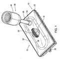
- FIG. 1 is perspective view of a combined filter and skimmer apparatus according to the invention
- FIG. 2 is a perspective view of the combined filter and skimmer apparatus with the lid removed;
- FIG. 3 is a side elevational view of the combined filter and skimmer apparatus
- FIG. 4A is a side sectional view of the combined filter and skimmer apparatus showing the filter media and illustrating with arrows the flow of water through the apparatus;
- FIG. 4B is an enlarged, fragmentarilly-illustrated side view showing the normal position of the floating cup relative to the pond water level;
- FIG. 4C is an enlarged, fragmentarilly-illustrated side view showing the position of the floating cup upon operation of the pump;
- FIGS. 5 A- 5 C illustrate the adjustable water inlet
- FIG. 6 is a view of the adjustable water inlet looking in the direction 6 - 6 of FIG. 5A.
- the apparatus 10 of the present invention includes a submersible filter box 12 containing replaceable filter media 14 (FIG. 4).
- the filter box 12 has a water inlet 16 , a skimmer coupling 18 , and a water outlet 20 .
- the water outlet 20 is adapted to be coupled to an underwater pump (not shown) which may, in turn, be coupled to a fountain (not shown).
- the filter box 12 is rectangular with a removable lid 22 . More particularly, as seen best in FIG. 3, the lid 22 and the box 12 engage each other via a plurality of snap couplings 23 such that the lid 22 remains coupled to the box 12 until it is intentionally removed.
- the filter media 14 is located in two sections 24 , 26 (FIG. 2) of the box 12 defined by two rows of baffles 28 , 30 which are spaced apart to define a channel 32 between the two sections 24 , 26 .
- the water outlet 20 is preferably aligned with (substantially collinear with) the channel 32 .
- the lid 22 has a raised central portion 34 (FIGS. 1, 3, and 4 ) wherein lies the water inlet 16 .
- the water inlet 16 is preferably adjustable as to the size of the inlet. More particularly, as shown in FIGS. 5 A- 5 C and 6 , the water inlet 16 includes a rotatable disk 19 having a handle 21 .
- the disk 19 has a plurality of windows 16 ′ and the cover 22 has a corresponding plurality of windows 17 .
- the disk 19 is rotatable from a position wherein the windows 16 ′ overlie the windows 17 to a position where the windows 17 are occluded. Adjusting the disk 19 will vary the amount of suction applied to the skimmer versus the filter i.e., the greater the number of “open” windows, the less amount of water drawn from the skimmer.
- the lid 22 is provided with a centrally located handle 25 by which the entire assembly may be lowered into and raised out of a pond (not shown).
- the skimmer coupling 18 is also located in the raised portion 34 of the lid 22 and is spaced apart from the water inlet 16 .
- the skimmer coupling 18 is coupled to an upstanding conduit 36 , the end of which is coupled to a skimmer head 38 .
- the skimmer head 38 preferably includes a floating cup 40 which, as shown in FIG. 4B, automatically adjusts to the level of the surface of the pond such that the top wall 41 thereof is located at or just below the waterline 49 of pond 50 .
- the floating cup 40 is free to tilt to adjust for an angular difference between the surface of the lid 22 and the surface of the pond (not shown).
- the floating cup 40 comprises an inverted U-shaped, double walled cylindrical sidewall composed of a top wall 41 joined, at its outer end, to a downward depending solid outer wall 42 and, at its inner end, to a downwardly depending slotted inner wall 43 having slots 45 which merges with a generally horizontally-extending base wall 48 .
- the inverted double-walled sidewall of floating cup 40 straddles the rim and/or side wall of a stationary, upstanding U-shaped cup 46 so that the floating cup 40 may move relative to fixed cup 46 while remaining in fluid connection and so that pond water may flow over top wall 41 into floating cup 40 through its slotted inner wall 43 into stationary cup 44 and, via conduit 36 and skimmer coupling 18 , into filter box 12 (see arrows).
- Cup 40 may be provided with a floatation material such as styrofoam (not shown), or preferably, may be floated via an air pocket trapped in the inverted U-shaped sidewall of floating cup 40 in the area adjacent top wall 41 ; the upper ends of slots 45 of inner sidewall 43 are spaced downwardly from top wall 41 so as to define an annular chamber 47 between the outer wall 42 and inner wall 43 and between top wall 41 and the upper end of slots 45 were air can be trapped.
- the floating cup 40 floats such that its top wall 47 is slightly above or at the water line 49 of the pond 50 (FIG. 4B).
- the presently preferred embodiment of the invention utilizes two replaceable “Bio-Matrix” cartridges ( 14 in FIG. 4A), each of which provides triple filtration for aquarium water.
- a dense white polyester filter media gives effective mechanical filtration while an activated carbon-impregnated polyester filter adds chemical filtration.
- the conduit 36 (FIGS. 1, 3, and 4 A) may be supplied in different lengths depending on the depth of the pond.
- the filter and skimmer of the invention is intended for ponds having a depth of 18 to 36 inches.
Landscapes
- Life Sciences & Earth Sciences (AREA)
- Environmental Sciences (AREA)
- Marine Sciences & Fisheries (AREA)
- Animal Husbandry (AREA)
- Biodiversity & Conservation Biology (AREA)
- Filtration Of Liquid (AREA)
Abstract
A combined filter and skimmer assembly for ponds includes a submersible filter box containing replaceable filter media, the filter box having a water inlet, a skimmer coupling coupled to an upstanding conduit coupled to a skimmer head, and a water outlet adapted to be coupled to an underwater pump. According to the presently preferred embodiment, the filter box is rectangular with a removable lid. The lid has a raised central portion wherein lies the water inlet. The water inlet is preferably adjustable as to the size of the inlet. The skimmer coupling is also located in the raised portion of the lid and is spaced apart from the water inlet. According to the presently preferred embodiment, the skimmer head preferably includes a floating cup which automatically adjusts to the level of the surface of the pond. Optionally the floating cup is free to tilt to adjust for an angular difference between the surface of the lid and the surface of the pond.
Description
- 1. Field of the Invention
- The invention relates to outdoor ponds. More particularly, the invention relates to an apparatus for filtering pond water and skimming the surface of the pond.
- 2. State of the Art
- Ponds have always been a desirable landscaping feature, particularly in conjunction with gardens. Until recently, however, artificial ponds have been relatively expensive to construct. With the advent of fish-safe polymer liner material that can be formed into any convenient shape, and covered with rock strata, natural looking artificial ponds have become a popular landscape feature.
- Both natural and artificial ponds require maintenance in order to remain aesthetically pleasing. Ponds should also provide a habitat not only for fish but other creatures such as birds, frogs, butterflies and the like. Clear water is the feature most desired in ponds so that fish and submerged plants may be viewable. However, maintaining the clarity of the water can be difficult. Algae, in particular free swimming algae, may cause the water to become cloudy. The excessive algae typically occurs when the water contains an excess of nutrients such as ammonia and phosphorous. This ammonia and phosphorous is generally added to pond water by fish waste and fertilizer runoff from the land surrounding the pond. Although aquatic plants may consume a portion of the nutrients, the number of plants is typically insufficient to handle the amount of excessive nutrients in a pond. Algae, which feed on these nutrients, then multiply due to the abundance of nutrients. This multiplication may result in algae “blooms” which cause the pond water to cloud.
- One method of clarifying water is to add chemicals to the water which destroy algae. However, these chemicals may destroy or have a negative impact on the number and growth of aquatic plants and fish. Also, chemicals must be replenished and this can be expensive.
- An additional maintenance problem involves the removal of leaves and other foliage which fall onto the surface of the pond. Unless it is soon removed from the surface, this foliage settles to the bottom where it decompose forming a layer of sludge. The sludge may reduce the depth of the pond and may also cover underwater formations. Removing the sludge requires draining the pond, a drastic procedure which requires temporary storage of fish and threatens the life of aquatic plants.
- With these issues in mind, several companies have looked to the art of swimming pool maintenance in an effort to design apparatus for filtering pond water and skimming the pond surface. Typical solutions based on swimming pool technology are disclosed in U.S. Pat. Nos. 5,584,991 and 6,054,045 to Wittstock et al. One of the main disadvantages of these solutions is that they require excavation and permanent installation. In many cases, these solutions must be installed when the pond is first constructed because pipes need to be laid beneath the pond. In addition, these solutions require that relatively large apparatus be arranged adjacent to the pond. These unsightly apparatus must be camouflaged with stones, shrubs, etc.
- The applicant herein has looked beyond swimming pool technology to provide the Pondmaster® filter system. The applicant's Pondmaster® filter system is fully submersible in an existing pond, does not require any excavation, and does not require unsightly apparatus to be located adjacent to the pond. It is modular and can be expanded to suit ponds of different sizes. However, the Pondmaster® system does not include a skimmer.
- It is therefore an object of the invention to provide a combined filter and skimmer assembly for ponds.
- It is also an object of the invention to provide a combined filter and skimmer assembly for ponds which is fully submersible in an existing pond.
- It is another object of the invention to provide a combined filter and skimmer assembly for ponds which does not require any excavation to be installed.
- It is still another object of the invention to provide a combined filter and skimmer assembly for ponds which does not require unsightly apparatus to be located adjacent to the pond.
- It is yet another object of the invention to provide a combined filter and skimmer assembly for ponds which is modular and can be expanded to suit ponds of different sizes.
- It is a further objection of the invention to provide a combined filter and skimmer assembly for ponds having a skimmer floating cup which is free to tilt to adjust for an angular difference between the water surface and the top surface of the floating cup.
- It is still a further object of the present invention to provide a combined filter and skimmer assembly for a pond having a floating cup which automatically adjusts to the level of the surface of the pond.
- In accord with these objects which will be discussed in detail below, the apparatus of the present invention includes a submersible filter box containing replaceable filter media, the filter box having a water inlet, a skimmer coupling, and a water outlet adapted to be coupled to an underwater pump. According to the presently preferred embodiment, the filter box is rectangular with a removable lid. The filter media is located in two sections of the box defined by two rows of baffles which are spaced apart to define a channel between the two sections. The water outlet is preferably aligned with the channel. The lid has a raised central portion wherein lies the water inlet. The water inlet is preferably adjustable as to the size of the inlet. The skimmer coupling is also located in the raised portion of the lid and is spaced apart from the water inlet. According to the presently preferred embodiment, the skimmer coupling is coupled to an upstanding conduit, the end of which is coupled to a skimmer head. The skimmer head preferably includes a floating cup which automatically adjusts to the level of the surface of the pond. Optionally the floating cup is free to tilt to adjust for an angular difference between the surface of the lid and the surface of the pond.
- Additional objects and advantages of the invention will become apparent to those skilled in the art upon reference to the detailed description taken in conjunction with the provided figures.
- FIG. 1 is perspective view of a combined filter and skimmer apparatus according to the invention;
- FIG. 2 is a perspective view of the combined filter and skimmer apparatus with the lid removed;
- FIG. 3 is a side elevational view of the combined filter and skimmer apparatus;
- FIG. 4A is a side sectional view of the combined filter and skimmer apparatus showing the filter media and illustrating with arrows the flow of water through the apparatus;
- FIG. 4B is an enlarged, fragmentarilly-illustrated side view showing the normal position of the floating cup relative to the pond water level;
- FIG. 4C is an enlarged, fragmentarilly-illustrated side view showing the position of the floating cup upon operation of the pump;
- FIGS. 5A-5C illustrate the adjustable water inlet; and
- FIG. 6 is a view of the adjustable water inlet looking in the direction 6-6 of FIG. 5A.
- Referring now to the Figures generally, the
apparatus 10 of the present invention includes asubmersible filter box 12 containing replaceable filter media 14 (FIG. 4). Thefilter box 12 has awater inlet 16, askimmer coupling 18, and awater outlet 20. Thewater outlet 20 is adapted to be coupled to an underwater pump (not shown) which may, in turn, be coupled to a fountain (not shown). - According to the presently preferred embodiment, the
filter box 12 is rectangular with aremovable lid 22. More particularly, as seen best in FIG. 3, thelid 22 and thebox 12 engage each other via a plurality ofsnap couplings 23 such that thelid 22 remains coupled to thebox 12 until it is intentionally removed. - The
filter media 14 is located in twosections 24, 26 (FIG. 2) of thebox 12 defined by two rows ofbaffles channel 32 between the twosections water outlet 20 is preferably aligned with (substantially collinear with) thechannel 32. - The
lid 22 has a raised central portion 34(FIGS. 1, 3, and 4) wherein lies thewater inlet 16. Thewater inlet 16 is preferably adjustable as to the size of the inlet. More particularly, as shown in FIGS. 5A-5C and 6, thewater inlet 16 includes arotatable disk 19 having ahandle 21. Thedisk 19 has a plurality ofwindows 16′ and thecover 22 has a corresponding plurality ofwindows 17. Thedisk 19 is rotatable from a position wherein thewindows 16′ overlie thewindows 17 to a position where thewindows 17 are occluded. Adjusting thedisk 19 will vary the amount of suction applied to the skimmer versus the filter i.e., the greater the number of “open” windows, the less amount of water drawn from the skimmer. - According to the presently preferred embodiment, as shown in FIGS. 1, 3, and 4, the
lid 22 is provided with a centrally located handle 25 by which the entire assembly may be lowered into and raised out of a pond (not shown). - As seen in FIGS. 1, 3, and 4A, the
skimmer coupling 18 is also located in the raisedportion 34 of thelid 22 and is spaced apart from thewater inlet 16. According to the presently preferred embodiment, theskimmer coupling 18 is coupled to anupstanding conduit 36, the end of which is coupled to askimmer head 38. Theskimmer head 38 preferably includes a floatingcup 40 which, as shown in FIG. 4B, automatically adjusts to the level of the surface of the pond such that thetop wall 41 thereof is located at or just below thewaterline 49 ofpond 50. Optionally, the floatingcup 40 is free to tilt to adjust for an angular difference between the surface of thelid 22 and the surface of the pond (not shown). - As seen best in FIGS. 4A-4C, the floating
cup 40 comprises an inverted U-shaped, double walled cylindrical sidewall composed of atop wall 41 joined, at its outer end, to a downward depending solidouter wall 42 and, at its inner end, to a downwardly depending slottedinner wall 43 havingslots 45 which merges with a generally horizontally-extending base wall 48. The inverted double-walled sidewall of floatingcup 40 straddles the rim and/or side wall of a stationary, upstandingU-shaped cup 46 so that the floatingcup 40 may move relative to fixedcup 46 while remaining in fluid connection and so that pond water may flow overtop wall 41 into floatingcup 40 through its slottedinner wall 43 into stationary cup 44 and, viaconduit 36 andskimmer coupling 18, into filter box 12 (see arrows). -
Cup 40 may be provided with a floatation material such as styrofoam (not shown), or preferably, may be floated via an air pocket trapped in the inverted U-shaped sidewall of floatingcup 40 in the area adjacenttop wall 41; the upper ends ofslots 45 ofinner sidewall 43 are spaced downwardly fromtop wall 41 so as to define anannular chamber 47 between theouter wall 42 andinner wall 43 and betweentop wall 41 and the upper end ofslots 45 were air can be trapped. As a result, the floatingcup 40 floats such that itstop wall 47 is slightly above or at thewater line 49 of the pond 50 (FIG. 4B). - Upon operation of the pump (not shown), water will be drawn from the
skimmer head 38, throughskimmer pond conduit 18 and intofilter box 12. Due to the pump operation, the normally floatingcup 40 will be drawn via suction downwardly such that itstop end 41 rests against the rim of stationary cup 46 (FIG. 4C). As a result,top wall 47 of floatingcup 40 is drawn below thewater line 49 ofpond 50, thereby allowing water at thewater line 49 to flow intocup 40. However, upon turning the pump off,cup 40 will assume its normal floating position due to the air trapped inannular chamber 47 beneath top wall 41 (FIG. 4B). As can be appreciated, the floating cup can also tilt to assume a level position with thepond surface 49 in the case the filter box is not perfectly horizontal when positioned on the floor of thepond 50. - The presently preferred embodiment of the invention utilizes two replaceable “Bio-Matrix” cartridges ( 14 in FIG. 4A), each of which provides triple filtration for aquarium water. A dense white polyester filter media gives effective mechanical filtration while an activated carbon-impregnated polyester filter adds chemical filtration. A presently preferred embodiment suitable for ponds up to 3,000 gallons when used with an 1,800 GPH pump, has a 12″×24” filter box and has a 1″ O.D. water outlet. The conduit 36 (FIGS. 1, 3, and 4A) may be supplied in different lengths depending on the depth of the pond. According to the presently preferred embodiment, the filter and skimmer of the invention is intended for ponds having a depth of 18 to 36 inches.
- There have been described and illustrated herein several embodiments of a combination filter and skimmer for a pond. While particular embodiments of the invention have been described, it is not intended that the invention be limited thereto, as it is intended that the invention be as broad in scope as the art will allow and that the specification be read likewise. It will therefore be appreciated by those skilled in the art that yet other modifications could be made to the provided invention without deviating from its spirit and scope as so claimed.
Claims (23)
1. A combined filter and skimmer assembly for a pond, comprising:
a) a filter box for containing a filter medium, said filter box having a skimmer coupling and a water outlet;
b) a water conduit coupled to said skimmer coupling; and
c) a skimmer head coupled to said water conduit, said skimmer head having a floating skimmer cup.
2. A combined filter and skimmer assembly according to claim 1 , further comprising:
d) removable filter media contained in said filter box.
3. A combined filter and skimmer assembly according to claim 1 , wherein:
said filter box has a removable lid.
4. A combined filter and skimmer assembly according to claim 3 , wherein:
said skimmer coupling is located on said removable lid.
5. A combined filter and skimmer assembly according to claim 4 , wherein:
said removable lid has a raised central portion and said skimmer coupling is located on said raised central portion.
6. A combined filter and skimmer assembly according to claim 1 , wherein:
said filter box has two sections defined by a plurality of spaced apart baffles.
7. A combined filter and skimmer assembly according to claim 6 , wherein:
said plurality of spaced apart baffles define a channel.
8. A combined filter and skimmer assembly according to claim 7 , wherein:
said water outlet is substantially collinear with said channel.
9. A combined filter and skimmer assembly according to claim 3 , wherein:
said removable lid has a centrally located handle.
10. A combined filter and skimmer assembly according to claim 9 , wherein:
said removable lid has an adjustable water inlet adjacent to said handle.
11. A combined filter and skimmer assembly for a pond, comprising:
a) a filter box for containing a filter medium, said filter box having a skimmer coupling, an adjustable water inlet and a water outlet;
b) a water conduit coupled to said skimmer coupling; and
c) a skimmer head coupled to said water conduit.
12. A combined filter and skimmer assembly according to claim 11 , further comprising:
d) removable filter media contained in said filter box.
13. A combined filter and skimmer assembly according to claim 11 , wherein:
said filter box has a removable lid.
14. A combined filter and skimmer assembly according to claim 13 , wherein:
said skimmer coupling is located on said removable lid.
15. A combined filter and skimmer assembly according to claim 14 , wherein:
said removable lid has a raised central portion and said skimmer coupling is located on said raised central portion.
16. A combined filter and skimmer assembly according to claim 11 , wherein:
said filter box has two sections defined by a plurality of spaced apart baffles.
17. A combined filter and skimmer assembly according to claim 16 , wherein:
said plurality of spaced apart baffles define a channel.
18. A combined filter and skimmer assembly according to claim 17 , wherein:
said water outlet is substantially collinear with said channel.
19. A combined filter and skimmer assembly according to claim 13 , wherein:
said removable lid has a centrally located handle.
20. A combined filter and skimmer assembly according to claim 15 , wherein:
said adjustable water inlet is located on said raised central portion.
21. A combined filter and skimmer assembly according to claim 1 , wherein:
said skimmer head comprises a stationary cup having a sidewall and an open top and bottom end, wherein said bottom end is fluidly coupled to said water conduit, and wherein said floating skimmer cup has an inverted doubled-walled sidewall which straddles at least a portion of said sidewall of said stationary cup.
22. A combined filter and skimmer assembly according to claim 21 , wherein:
said floating skimmer cup has a top wall, a downwardly depending outer sidewall joined to the outer end of said top wall and a downwardly depending inner slotted sidewall joined to said inner end of said top wall.
23. A combined filter and skimmer assembly according to claim 22 , wherein said slotted inner sidewall has slots spaced beneath said top wall so as to define an annular chamber beneath said top wall in which air may be trapped.
Priority Applications (1)
| Application Number | Priority Date | Filing Date | Title |
|---|---|---|---|
| US10/128,625 US6709582B2 (en) | 2002-04-22 | 2002-04-22 | Combined filter and skimmer assembly for ponds |
Applications Claiming Priority (1)
| Application Number | Priority Date | Filing Date | Title |
|---|---|---|---|
| US10/128,625 US6709582B2 (en) | 2002-04-22 | 2002-04-22 | Combined filter and skimmer assembly for ponds |
Publications (2)
| Publication Number | Publication Date |
|---|---|
| US20030196941A1 true US20030196941A1 (en) | 2003-10-23 |
| US6709582B2 US6709582B2 (en) | 2004-03-23 |
Family
ID=29215488
Family Applications (1)
| Application Number | Title | Priority Date | Filing Date |
|---|---|---|---|
| US10/128,625 Expired - Fee Related US6709582B2 (en) | 2002-04-22 | 2002-04-22 | Combined filter and skimmer assembly for ponds |
Country Status (1)
| Country | Link |
|---|---|
| US (1) | US6709582B2 (en) |
Cited By (8)
| Publication number | Priority date | Publication date | Assignee | Title |
|---|---|---|---|---|
| US20040182765A1 (en) * | 2003-03-20 | 2004-09-23 | Mauro Joseph K. | Artificial pond |
| US20050263446A1 (en) * | 2004-05-27 | 2005-12-01 | Edgar Beaulieu | Skimmer construction |
| US20060033332A1 (en) * | 2004-08-11 | 2006-02-16 | Pentair Pool Products, Inc. | Snap-fit connection for pool filtration systems |
| US20070107664A1 (en) * | 2005-11-15 | 2007-05-17 | Pondsweep Manufacturing Company | Landscaping pond system and method with variable opening falls and tesserae geometry |
| US20110079555A1 (en) * | 2009-10-06 | 2011-04-07 | Aquatica Gallery Llc | Aquarium Filter |
| US9668461B1 (en) * | 2012-06-15 | 2017-06-06 | The Pond Digger, Inc. | Skimmer assembly for ponds and water features |
| US20200376420A1 (en) * | 2019-05-28 | 2020-12-03 | Plenty Company, LLC | Water pitcher with float and underside filter |
| US20220159937A1 (en) * | 2020-11-20 | 2022-05-26 | Robert Douglas Schmidt | Aquarium skimmer devices, systems, and methods |
Families Citing this family (11)
| Publication number | Priority date | Publication date | Assignee | Title |
|---|---|---|---|---|
| US20050167347A1 (en) * | 2004-02-04 | 2005-08-04 | Thomas Charles W. | Ornamental waterfall |
| US20060071338A1 (en) * | 2004-09-30 | 2006-04-06 | International Business Machines Corporation | Homogeneous Copper Interconnects for BEOL |
| US8961153B2 (en) * | 2008-02-29 | 2015-02-24 | Schlumberger Technology Corporation | Subsea injection system |
| IT1398449B1 (en) * | 2009-01-21 | 2013-02-22 | Hydor Srl | FOAM FOR AQUARIUMS |
| US8475656B1 (en) * | 2010-07-20 | 2013-07-02 | Michael E. Neumann | Floating surface skimmer |
| US20120234744A1 (en) * | 2010-09-03 | 2012-09-20 | General Foam Plastics Corporation | Filtration system |
| US8387174B1 (en) * | 2011-01-25 | 2013-03-05 | Nicki Sue Gillespie | Swimming pool skimmer creature raft rescue device |
| ES2874302T3 (en) * | 2016-12-08 | 2021-11-04 | Seabin Pty Ltd | Waste collection device |
| US10876313B1 (en) | 2019-06-17 | 2020-12-29 | Robert Douglas Schmidt | Pool skimmer devices, systems, and methods |
| US11332950B2 (en) * | 2019-08-29 | 2022-05-17 | Robert Douglas Schmidt | Pool skimmer devices, systems, and methods |
| US11725407B2 (en) | 2020-07-21 | 2023-08-15 | Robert Douglas Schmidt | Pool skimmer devices, systems, and methods |
Citations (17)
| Publication number | Priority date | Publication date | Assignee | Title |
|---|---|---|---|---|
| US444500A (en) * | 1891-01-13 | Jfsjfj | ||
| US687423A (en) * | 1901-01-23 | 1901-11-26 | Victory Oil Filter Company | Oil-filter. |
| US717932A (en) * | 1902-10-01 | 1903-01-06 | Charles Scudder | Filter. |
| US763325A (en) * | 1903-09-04 | 1904-06-21 | George A Hancock | Floating water-filter. |
| US1647809A (en) * | 1925-07-23 | 1927-11-01 | John Astrom | Floating filter |
| US3303932A (en) * | 1966-06-27 | 1967-02-14 | Hydromation Engineering Compan | Level seeking skimmer |
| US3402817A (en) * | 1967-05-05 | 1968-09-24 | Filtration Equipment Corp | Ballast operated filter |
| US5028320A (en) * | 1989-12-04 | 1991-07-02 | Gaudin Carl J | Sewer catch basin with gas seal for a petroleum refinery or chemical processing plant |
| US5133854A (en) * | 1990-07-13 | 1992-07-28 | Tibor Horvath | Skimmer with self-adjusting floating collector |
| US5143605A (en) * | 1991-11-25 | 1992-09-01 | David Masciarelli | Mobile floating skimmer |
| US5275721A (en) * | 1993-02-08 | 1994-01-04 | Oommen Mathews | Swimming pool super-skimmer |
| US5814213A (en) * | 1997-11-10 | 1998-09-29 | Glasgow; James A. | Skimming apparatus |
| US6027641A (en) * | 1994-11-24 | 2000-02-22 | Cornelia Johanna Spradbury | Liquid surface skimmer |
| US6274047B1 (en) * | 2000-03-13 | 2001-08-14 | Gary G. Bates | Skimmer assembly |
| US6299765B1 (en) * | 1999-05-19 | 2001-10-09 | Robert A. Fabrizio | Surface feed filter pump box for aquariums |
| US6461501B1 (en) * | 2001-05-11 | 2002-10-08 | Hardscape Materials, Inc. | Ornamental pond skimmer and filter apparatus |
| US20020179507A1 (en) * | 2001-05-30 | 2002-12-05 | Wolford James B. | Transmission sump filter with bypass valve |
Family Cites Families (1)
| Publication number | Priority date | Publication date | Assignee | Title |
|---|---|---|---|---|
| DE567646C (en) * | 1933-01-06 | Kurt Mueller | Ironing device connected in front of or behind the take-off device of knitting or knitting machines |
-
2002
- 2002-04-22 US US10/128,625 patent/US6709582B2/en not_active Expired - Fee Related
Patent Citations (17)
| Publication number | Priority date | Publication date | Assignee | Title |
|---|---|---|---|---|
| US444500A (en) * | 1891-01-13 | Jfsjfj | ||
| US687423A (en) * | 1901-01-23 | 1901-11-26 | Victory Oil Filter Company | Oil-filter. |
| US717932A (en) * | 1902-10-01 | 1903-01-06 | Charles Scudder | Filter. |
| US763325A (en) * | 1903-09-04 | 1904-06-21 | George A Hancock | Floating water-filter. |
| US1647809A (en) * | 1925-07-23 | 1927-11-01 | John Astrom | Floating filter |
| US3303932A (en) * | 1966-06-27 | 1967-02-14 | Hydromation Engineering Compan | Level seeking skimmer |
| US3402817A (en) * | 1967-05-05 | 1968-09-24 | Filtration Equipment Corp | Ballast operated filter |
| US5028320A (en) * | 1989-12-04 | 1991-07-02 | Gaudin Carl J | Sewer catch basin with gas seal for a petroleum refinery or chemical processing plant |
| US5133854A (en) * | 1990-07-13 | 1992-07-28 | Tibor Horvath | Skimmer with self-adjusting floating collector |
| US5143605A (en) * | 1991-11-25 | 1992-09-01 | David Masciarelli | Mobile floating skimmer |
| US5275721A (en) * | 1993-02-08 | 1994-01-04 | Oommen Mathews | Swimming pool super-skimmer |
| US6027641A (en) * | 1994-11-24 | 2000-02-22 | Cornelia Johanna Spradbury | Liquid surface skimmer |
| US5814213A (en) * | 1997-11-10 | 1998-09-29 | Glasgow; James A. | Skimming apparatus |
| US6299765B1 (en) * | 1999-05-19 | 2001-10-09 | Robert A. Fabrizio | Surface feed filter pump box for aquariums |
| US6274047B1 (en) * | 2000-03-13 | 2001-08-14 | Gary G. Bates | Skimmer assembly |
| US6461501B1 (en) * | 2001-05-11 | 2002-10-08 | Hardscape Materials, Inc. | Ornamental pond skimmer and filter apparatus |
| US20020179507A1 (en) * | 2001-05-30 | 2002-12-05 | Wolford James B. | Transmission sump filter with bypass valve |
Cited By (13)
| Publication number | Priority date | Publication date | Assignee | Title |
|---|---|---|---|---|
| US20040182765A1 (en) * | 2003-03-20 | 2004-09-23 | Mauro Joseph K. | Artificial pond |
| US7153418B2 (en) * | 2003-03-20 | 2006-12-26 | Campbell Hausfeld/Scott Fetzer Company | Artificial pond |
| US20050263446A1 (en) * | 2004-05-27 | 2005-12-01 | Edgar Beaulieu | Skimmer construction |
| US7144501B2 (en) * | 2004-05-27 | 2006-12-05 | Aquascape Designs, Inc. | Skimmer construction |
| US20060033332A1 (en) * | 2004-08-11 | 2006-02-16 | Pentair Pool Products, Inc. | Snap-fit connection for pool filtration systems |
| US7207604B2 (en) | 2004-08-11 | 2007-04-24 | Pentair Pool Products, Inc. | Snap-fit connection for pool filtration systems |
| US20070107664A1 (en) * | 2005-11-15 | 2007-05-17 | Pondsweep Manufacturing Company | Landscaping pond system and method with variable opening falls and tesserae geometry |
| US20110079555A1 (en) * | 2009-10-06 | 2011-04-07 | Aquatica Gallery Llc | Aquarium Filter |
| US9668461B1 (en) * | 2012-06-15 | 2017-06-06 | The Pond Digger, Inc. | Skimmer assembly for ponds and water features |
| US20200376420A1 (en) * | 2019-05-28 | 2020-12-03 | Plenty Company, LLC | Water pitcher with float and underside filter |
| US11596882B2 (en) * | 2019-05-28 | 2023-03-07 | Plenty Company, LLC | Water pitcher with float and underside filter |
| US20220159937A1 (en) * | 2020-11-20 | 2022-05-26 | Robert Douglas Schmidt | Aquarium skimmer devices, systems, and methods |
| US11895991B2 (en) * | 2020-11-20 | 2024-02-13 | Robert Douglas Schmidt | Aquarium skimmer devices, systems, and methods |
Also Published As
| Publication number | Publication date |
|---|---|
| US6709582B2 (en) | 2004-03-23 |
Similar Documents
| Publication | Publication Date | Title |
|---|---|---|
| US6709582B2 (en) | Combined filter and skimmer assembly for ponds | |
| US5584991A (en) | Filtration system for ponds | |
| US7114668B2 (en) | Constructed wetlands system, treatment apparatus and method | |
| US6290844B1 (en) | Filter systems and methods for pond water pump systems | |
| US20080061010A1 (en) | Filter System for Ponds and Larger Aquariums | |
| US6843910B1 (en) | Ornamental pond | |
| KR102096206B1 (en) | Facilities for the aquaculture using floating vessel, barge and structures | |
| US3722685A (en) | Aquatic filtration system | |
| US6709580B2 (en) | Pond skimmer | |
| US20090094889A1 (en) | Aquatic plant stands | |
| CN107866102A (en) | Floating type water purification system | |
| US20250344679A1 (en) | Systems and methods for treatment and filtration of water | |
| CN118062999A (en) | An initial rainwater ecological purification corridor and construction method thereof | |
| US20050167347A1 (en) | Ornamental waterfall | |
| US6527949B1 (en) | Landscaping pond system | |
| US20050098493A1 (en) | Water filter | |
| KR100593852B1 (en) | Water Purification System Using Upward Flowable Floating Contact Module | |
| US4669914A (en) | Hydrologic discharge control assembly and method | |
| KR20100009815A (en) | Apparatus preserving sea water for salt pan | |
| JP3180169B2 (en) | Underwater water storage device | |
| KR100363589B1 (en) | Cistern for pond and pond system using it | |
| JP3150947B2 (en) | Water purification device | |
| JP2910816B2 (en) | Aquaculture pond water exchange device and water exchange method | |
| Van Wyk | Harbor branch shrimp production systems | |
| JP2001321158A (en) | Method for producing filamentous diatoms |
Legal Events
| Date | Code | Title | Description |
|---|---|---|---|
| REMI | Maintenance fee reminder mailed | ||
| LAPS | Lapse for failure to pay maintenance fees | ||
| LAPS | Lapse for failure to pay maintenance fees |
Free format text: PATENT EXPIRED FOR FAILURE TO PAY MAINTENANCE FEES (ORIGINAL EVENT CODE: EXP.); ENTITY STATUS OF PATENT OWNER: SMALL ENTITY |
|
| STCH | Information on status: patent discontinuation |
Free format text: PATENT EXPIRED DUE TO NONPAYMENT OF MAINTENANCE FEES UNDER 37 CFR 1.362 |
|
| FP | Lapsed due to failure to pay maintenance fee |
Effective date: 20080323 |