US20030196879A1 - Housing contained fluid flow and indicator - Google Patents
Housing contained fluid flow and indicator Download PDFInfo
- Publication number
- US20030196879A1 US20030196879A1 US10/340,430 US34043003A US2003196879A1 US 20030196879 A1 US20030196879 A1 US 20030196879A1 US 34043003 A US34043003 A US 34043003A US 2003196879 A1 US2003196879 A1 US 2003196879A1
- Authority
- US
- United States
- Prior art keywords
- bore
- movable contact
- housing
- electrical
- fluid
- Prior art date
- Legal status (The legal status is an assumption and is not a legal conclusion. Google has not performed a legal analysis and makes no representation as to the accuracy of the status listed.)
- Granted
Links
Images


Classifications
-
- H—ELECTRICITY
- H01—ELECTRIC ELEMENTS
- H01H—ELECTRIC SWITCHES; RELAYS; SELECTORS; EMERGENCY PROTECTIVE DEVICES
- H01H35/00—Switches operated by change of a physical condition
- H01H35/24—Switches operated by change of fluid pressure, by fluid pressure waves, or by change of fluid flow
- H01H35/40—Switches operated by change of fluid pressure, by fluid pressure waves, or by change of fluid flow actuated by devices allowing continual flow of fluid, e.g. vane
-
- H—ELECTRICITY
- H01—ELECTRIC ELEMENTS
- H01H—ELECTRIC SWITCHES; RELAYS; SELECTORS; EMERGENCY PROTECTIVE DEVICES
- H01H1/00—Contacts
- H01H1/12—Contacts characterised by the manner in which co-operating contacts engage
- H01H1/14—Contacts characterised by the manner in which co-operating contacts engage by abutting
- H01H1/24—Contacts characterised by the manner in which co-operating contacts engage by abutting with resilient mounting
-
- H—ELECTRICITY
- H01—ELECTRIC ELEMENTS
- H01H—ELECTRIC SWITCHES; RELAYS; SELECTORS; EMERGENCY PROTECTIVE DEVICES
- H01H35/00—Switches operated by change of a physical condition
- H01H35/24—Switches operated by change of fluid pressure, by fluid pressure waves, or by change of fluid flow
- H01H35/245—Switches operated by change of fluid pressure, by fluid pressure waves, or by change of fluid flow actuated by the deformation of a body of elastic material
-
- Y—GENERAL TAGGING OF NEW TECHNOLOGICAL DEVELOPMENTS; GENERAL TAGGING OF CROSS-SECTIONAL TECHNOLOGIES SPANNING OVER SEVERAL SECTIONS OF THE IPC; TECHNICAL SUBJECTS COVERED BY FORMER USPC CROSS-REFERENCE ART COLLECTIONS [XRACs] AND DIGESTS
- Y10—TECHNICAL SUBJECTS COVERED BY FORMER USPC
- Y10T—TECHNICAL SUBJECTS COVERED BY FORMER US CLASSIFICATION
- Y10T29/00—Metal working
- Y10T29/49—Method of mechanical manufacture
- Y10T29/49002—Electrical device making
- Y10T29/49105—Switch making
Definitions
- the present invention relates to fluid flow indicators and specifically to an indicator that provides a visual indication of a pulsating fluid flow.
- lubrication devices in the design of industrial machinery.
- lubricant may be provided to bearings, journals, chains, sprockets and other machine components.
- the lubrication devices may include pumps that meter lubricant to the machine at a predetermined level or at predetermined time intervals.
- the lubricant is typically stored in a lubricant supply source, such as a tank and then delivered by a conduit to a pump.
- the amount of lubricant in the tank or other supply source may be monitored by a sight gage, float gage, or similar device.
- a second conduit directs the lubricant from the pump either to the machine or to a lubricant manifold where it may be subsequently sent to multiple locations on the machine.
- the present invention relates to a device for monitoring fluid flow from a pressurized fluid output, such as the output from a pump or metering device.
- the fluid flow indictor activates an indicator, such as a light emitting diode, in response to a predetermined increase in the pressure of the fluid flowing through a conduit.
- an indicator such as a light emitting diode
- a pulse is generated by an increase in fluid pressure across a specified plane within a cavity or chamber, followed by a pressure drop across the plane, and then equalization of the pressure across the plane. This pulse translates into instantaneous force acting on the plane.
- a disk is placed in the plane causing the pulse to be amplified. The disk is then unidirectionally linearly dampened with a conical spring, resulting in displacement of the disk along a linear axis from an initial position to a second position.
- the invention utilizes a power supply, such as one or more button cell batteries, and a visual indicator, such as a light-emitting diode (LED), in a closed loop circuit with the spring and the disk.
- a visual indicator such as a light-emitting diode (LED)
- the spring and disk assembly functions as switch, closing the circuit when the fluid pressure reaches a predetermined level. This results in illumination of the indicator.
- the device allows for a continuous visual monitoring of the fluid flow in a display on the LED.
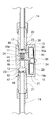
- FIG. 1 is a perspective view of the fluid flow indicator of the present invention
- FIG. 2 is an exploded perspective view of the fluid flow indicator
- FIG. 3 is a side elevational view of the indicator assembly installed in a typical fluid flow circuit.
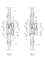
- FIG. 4 is a cut-away side elevational view of the indicator with no fluid flowing.
- FIG. 5 is a cut-away side elevational view of the indicator during fluid flow.
- the fluid flow sensor assembly of the present invention is designated generally by the reference numeral 10 .
- a housing 11 has a longitudinal through bore 12 extending from the housing 11 top surface 13 to its bottom surface 15 .
- a pair of counter bores 23 is formed inwardly from both the top surface 13 and the bottom surface 15 .
- the counter bore 23 at the top surface is preferably provided at its inlet end with threads 17 engageable with a threaded pipe nipple 20 .
- the counter bore 23 at the lower end of the bore 12 is provided with threads 18 engageable with an outlet pipe nipple 21 . (See FIGS. 4 and 5.)
- the nipples 20 and 21 are threaded to a conduit 14 located in a fluid flow line emanating from a tank of fluid to be sensed by the sensor assembly 10 (not shown).
- An elongated milled slot 26 is formed in the front face 16 of the housing 11 .
- Two large counter-bores 30 and 31 are sized to each hold a pair of batteries 19 a and 19 b , and are further configured to define the slot 26 .
- the respective axes of the counter-bores 30 , 31 preferably lie substantially perpendicular to the axis of the longitudinal bore 12 .
- a smaller diameter counter-bore 34 is formed parallel to and between the aforementioned larger counter-bores 30 , 31 and is arranged to retain a light-emitting diode (LED) 36 .
- LED light-emitting diode
- Within the uppermost larger counter-bore 30 there is a centrally located small diameter bore 38 (see FIG. 4).
- the small diameter counter-bore 38 extends diametrically across the longitudinal bore 12 to intersect with the shoulder 24 formed at the junction of counter bore 23 and the bore 12 .
- the bore 38 is arranged to receive a wire lead 40 emanating from the battery 19 a and having a flat contact portion 40 a resting on the shoulder 24 and lying transversely across the diameter of the counter bore portion 23 of the bore 12 .
- the housing 11 is preferably fabricated from acetyl or other non-conducting material.
- a contact disk 42 is secured to a conical spring 44 and the assembly is inserted into the upper opening or fluid inlet end of the bore 12 in the housing 11 .
- the disk 42 and spring 44 are preferably fabricated from brass and stainless steel, respectively.
- the electrically conductive wire battery lead 40 provides a stationary contact for electrically mating with the contact disk 42 through spring 44 during fluid flow pressing against the disk 42 .
- the lead 40 is inserted within the bore 38 in the upper battery pocket 30 , extending across the counter bore 23 to rest on the shoulder 24 .
- the end of the push wire lead 40 is bent over allowing a battery 19 a to be inserted into the battery pocket 30 .
- the light emitting diode 36 has two leads 46 , 47 .
- Lead 46 is known as the anode and lead 47 is known as the cathode.
- the anode lead 46 is trimmed to a length of ⁇ fraction (21/32) ⁇ inches.
- the cathode lead 47 is trimmed to a length of ⁇ fraction (5/16) ⁇ inches and then bent at substantially right angle as shown in FIGS. 1, 4 and 5 .
- the LED 36 is inserted into the LED counter bore 38 .
- the LED 36 is a high efficiency green at 45 degrees cone angle LED that is daylight visible.
- the batteries 19 a and 19 b supply power to the indicator assembly 10 .
- the batteries are conventional silver oxide button cell batteries having a predetermined power rating.
- Each battery 19 a , 19 b is placed into its respective battery pocket, or counterbore 30 and 31 .
- the counter-bores 30 and 31 are each dimensionally contoured to accommodate a respective button cell battery 19 a and 19 b .
- An electrically conductive battery jumper tab 22 retains the batteries 19 a , 19 b .
- the tab 22 is placed over the batteries 19 a , 19 b and is retained by a pair of drive mounting studs 25 (See FIG. 2).
- the studs 25 engage with a friction fit into openings 27 formed in the housing 11 .
- the tab 22 has a central opening 29 formed therein.
- the LED 36 passes through the central opening 29 when the tab or jumper 22 is installed.
- a conventional, epoxy-based potting compound 49 is mixed and poured into the milled slot 26 and over the above-described components. Care must be taken to insure that the potting compound 49 does not coat the LED 36 or overflow from the slot 26 . The potting compound 49 cures in approximately 12 hours, during which time the indicator assembly 10 should remain on a flat surface.
- the helical spring 44 , push wire lead 40 , contact disk 42 , LED 36 , batteries 19 a , 19 b and jumper tab 22 form an electrical circuit.
- the batteries 19 a , 19 b are connected in series by the jumper tab 22 .
- the push wire lead 40 connects the upper battery 19 a to one end of the helical spring 44 .
- the helical spring 44 coupled to the contact disk 42 forms a switch in conjunction with lead wire 46 of the LED 36 .
- the other lead wire 47 (cathode), emanating from LED 36 is connected to the other battery 19 b .
- the indicator assembly 10 is installed between a fluid inlet 48 and a fluid outlet 50 .
- Fluid flows under a predetermined pressure into the indicator 10 from a source, such as a PURGEX® metering pump, manufactured by OIL-RITE® CORPORATION of Manitowoc, Wis.
- a source such as a PURGEX® metering pump, manufactured by OIL-RITE® CORPORATION of Manitowoc, Wis.
- a source such as a PURGEX® metering pump, manufactured by OIL-RITE® CORPORATION of Manitowoc, Wis.
- the fluid pressure overcomes the resistance of the spring 44 attached to the disk 42 .
- the disk 42 is displaced from its initial position to a second position where it contacts the lead wire 46 as shown in FIG. 5, thereby completing the electrical circuit.
- the LED 36 illuminates.
- the spring force overcomes the fluid force and the disk 14 moves back to its initial position as shown in FIG. 4.
- the electrical circuit will be completed again and the LED 36 will be illuminated.
- the illuminated LED 36 provides a visual indication that fluid is flowing through the indicator assembly 10 .
Landscapes
- Physics & Mathematics (AREA)
- Fluid Mechanics (AREA)
- Indicating Or Recording The Presence, Absence, Or Direction Of Movement (AREA)
Abstract
Description
- This application claims the benefit of prior application Ser. No. 60/373,729, filed Apr. 18, 2002.
- The present invention relates to fluid flow indicators and specifically to an indicator that provides a visual indication of a pulsating fluid flow.
- It is common to include lubrication devices in the design of industrial machinery. Specifically, lubricant may be provided to bearings, journals, chains, sprockets and other machine components. The lubrication devices may include pumps that meter lubricant to the machine at a predetermined level or at predetermined time intervals. The lubricant is typically stored in a lubricant supply source, such as a tank and then delivered by a conduit to a pump. The amount of lubricant in the tank or other supply source may be monitored by a sight gage, float gage, or similar device. A second conduit directs the lubricant from the pump either to the machine or to a lubricant manifold where it may be subsequently sent to multiple locations on the machine.
- In most applications if the supply tank is full, it is assumed that lubricant is being delivered to the machine component. However, it the supply conduit breaks or the pump malfunctions, there is typically no indication of lack of lubricant flow until a machine component fails. There is a need for a device that monitors fluid flow downstream of the lubricant pump and provides a confirming signal that fluid is flowing from the pump outlet.
- The present invention relates to a device for monitoring fluid flow from a pressurized fluid output, such as the output from a pump or metering device. The fluid flow indictor activates an indicator, such as a light emitting diode, in response to a predetermined increase in the pressure of the fluid flowing through a conduit. Specifically, a pulse is generated by an increase in fluid pressure across a specified plane within a cavity or chamber, followed by a pressure drop across the plane, and then equalization of the pressure across the plane. This pulse translates into instantaneous force acting on the plane. A disk is placed in the plane causing the pulse to be amplified. The disk is then unidirectionally linearly dampened with a conical spring, resulting in displacement of the disk along a linear axis from an initial position to a second position.
- The invention utilizes a power supply, such as one or more button cell batteries, and a visual indicator, such as a light-emitting diode (LED), in a closed loop circuit with the spring and the disk. The spring and disk assembly functions as switch, closing the circuit when the fluid pressure reaches a predetermined level. This results in illumination of the indicator. Thus, as pressurized fluid flows through the conduit, the device allows for a continuous visual monitoring of the fluid flow in a display on the LED.
- FIG. 1 is a perspective view of the fluid flow indicator of the present invention;
- FIG. 2 is an exploded perspective view of the fluid flow indicator;
- FIG. 3 is a side elevational view of the indicator assembly installed in a typical fluid flow circuit.
- FIG. 4 is a cut-away side elevational view of the indicator with no fluid flowing; and
- FIG. 5 is a cut-away side elevational view of the indicator during fluid flow.
- Referring to the drawings, the fluid flow sensor assembly of the present invention is designated generally by the
reference numeral 10. Ahousing 11 has a longitudinal throughbore 12 extending from thehousing 11top surface 13 to itsbottom surface 15. A pair ofcounter bores 23 is formed inwardly from both thetop surface 13 and thebottom surface 15. The counter bore 23 at the top surface is preferably provided at its inlet end withthreads 17 engageable with a threadedpipe nipple 20. The counter bore 23 at the lower end of thebore 12 is provided withthreads 18 engageable with anoutlet pipe nipple 21. (See FIGS. 4 and 5.) Thenipples conduit 14 located in a fluid flow line emanating from a tank of fluid to be sensed by the sensor assembly 10 (not shown). - An
elongated milled slot 26 is formed in thefront face 16 of thehousing 11. Twolarge counter-bores batteries slot 26. The respective axes of thecounter-bores longitudinal bore 12. - Referring next to FIG. 2, a
smaller diameter counter-bore 34 is formed parallel to and between the aforementionedlarger counter-bores larger counter-bore 30, there is a centrally located small diameter bore 38 (see FIG. 4). Thesmall diameter counter-bore 38 extends diametrically across thelongitudinal bore 12 to intersect with theshoulder 24 formed at the junction ofcounter bore 23 and thebore 12. Thebore 38 is arranged to receive awire lead 40 emanating from thebattery 19 a and having aflat contact portion 40 a resting on theshoulder 24 and lying transversely across the diameter of thecounter bore portion 23 of thebore 12. Thehousing 11 is preferably fabricated from acetyl or other non-conducting material. - A
contact disk 42 is secured to aconical spring 44 and the assembly is inserted into the upper opening or fluid inlet end of thebore 12 in thehousing 11. Thedisk 42 andspring 44 are preferably fabricated from brass and stainless steel, respectively. The electrically conductivewire battery lead 40 provides a stationary contact for electrically mating with thecontact disk 42 throughspring 44 during fluid flow pressing against thedisk 42. Thelead 40 is inserted within thebore 38 in theupper battery pocket 30, extending across the counter bore 23 to rest on theshoulder 24. The end of thepush wire lead 40 is bent over allowing abattery 19 a to be inserted into thebattery pocket 30. Thelight emitting diode 36 has twoleads Lead 46 is known as the anode andlead 47 is known as the cathode. Theanode lead 46 is trimmed to a length of {fraction (21/32)} inches. Thecathode lead 47 is trimmed to a length of {fraction (5/16)} inches and then bent at substantially right angle as shown in FIGS. 1, 4 and 5. TheLED 36 is inserted into theLED counter bore 38. In a preferred embodiment, theLED 36 is a high efficiency green at 45 degrees cone angle LED that is daylight visible. - The
batteries indicator assembly 10. In the preferred embodiment, the batteries are conventional silver oxide button cell batteries having a predetermined power rating. Eachbattery counterbore counter-bores button cell battery battery jumper tab 22 retains thebatteries tab 22 is placed over thebatteries studs 25 engage with a friction fit intoopenings 27 formed in thehousing 11. It should be noted that thetab 22 has acentral opening 29 formed therein. TheLED 36 passes through thecentral opening 29 when the tab orjumper 22 is installed. - Finally, a conventional, epoxy-based
potting compound 49 is mixed and poured into the milledslot 26 and over the above-described components. Care must be taken to insure that the pottingcompound 49 does not coat theLED 36 or overflow from theslot 26. The pottingcompound 49 cures in approximately 12 hours, during which time theindicator assembly 10 should remain on a flat surface. - As best seen in FIGS. 4 and 5, the
helical spring 44,push wire lead 40,contact disk 42,LED 36,batteries jumper tab 22 form an electrical circuit. Thebatteries jumper tab 22. Thepush wire lead 40 connects theupper battery 19 a to one end of thehelical spring 44. Thehelical spring 44, coupled to thecontact disk 42 forms a switch in conjunction withlead wire 46 of theLED 36. The other lead wire 47 (cathode), emanating fromLED 36, is connected to theother battery 19 b. When thedisk 42 contacts theanode lead 46 of theLED 36, the electrical circuit is closed thereby illuminating theLED 36. When thedisk 42 retracts under the force ofspring 44, the circuit is opened and theLED 36 is no longer illuminated. - Again referring to FIGS. 4 and 5, the
indicator assembly 10 is installed between afluid inlet 48 and afluid outlet 50. Fluid flows under a predetermined pressure into theindicator 10 from a source, such as a PURGEX® metering pump, manufactured by OIL-RITE® CORPORATION of Manitowoc, Wis. As the fluid contacts thedisk 42, the fluid pressure overcomes the resistance of thespring 44 attached to thedisk 42. Thedisk 42 is displaced from its initial position to a second position where it contacts thelead wire 46 as shown in FIG. 5, thereby completing the electrical circuit. When the electrical circuit is closed, theLED 36 illuminates. As the pressure from the pulse of the fluid diminishes, the spring force overcomes the fluid force and thedisk 14 moves back to its initial position as shown in FIG. 4. When the metering pump expels the next fluid pulse, the electrical circuit will be completed again and theLED 36 will be illuminated. The illuminatedLED 36 provides a visual indication that fluid is flowing through theindicator assembly 10. - The foregoing is considered as illustrative only of the principles of the invention. Furthermore, since numerous modifications and changes will readily occur to those skilled in the art, it is not desired to limit the invention to the exact construction and operation shown and described. While the preferred embodiment has been described, the details may be changed without departing from the invention.
Claims (10)
Priority Applications (1)
| Application Number | Priority Date | Filing Date | Title |
|---|---|---|---|
| US10/340,430 US6635836B1 (en) | 2002-04-18 | 2003-01-10 | Housing contained fluid flow switch and indicator |
Applications Claiming Priority (2)
| Application Number | Priority Date | Filing Date | Title |
|---|---|---|---|
| US37372902P | 2002-04-18 | 2002-04-18 | |
| US10/340,430 US6635836B1 (en) | 2002-04-18 | 2003-01-10 | Housing contained fluid flow switch and indicator |
Publications (2)
| Publication Number | Publication Date |
|---|---|
| US6635836B1 US6635836B1 (en) | 2003-10-21 |
| US20030196879A1 true US20030196879A1 (en) | 2003-10-23 |
Family
ID=28794279
Family Applications (1)
| Application Number | Title | Priority Date | Filing Date |
|---|---|---|---|
| US10/340,430 Expired - Fee Related US6635836B1 (en) | 2002-04-18 | 2003-01-10 | Housing contained fluid flow switch and indicator |
Country Status (1)
| Country | Link |
|---|---|
| US (1) | US6635836B1 (en) |
Cited By (1)
| Publication number | Priority date | Publication date | Assignee | Title |
|---|---|---|---|---|
| WO2005029547A3 (en) * | 2003-09-16 | 2005-07-14 | Univ Columbia | Enhancing the width of polycrystalline grains with mask |
Families Citing this family (5)
| Publication number | Priority date | Publication date | Assignee | Title |
|---|---|---|---|---|
| US7298280B2 (en) * | 2003-06-06 | 2007-11-20 | Ameriflo Inc. | Lighted fluid flow indication apparatus |
| TWD130232S1 (en) * | 2008-04-18 | 2009-08-11 | 股份有限公司 | Flow switch |
| TWD130231S1 (en) * | 2008-04-18 | 2009-08-11 | 股份有限公司 | Flow switch |
| TWD133529S1 (en) * | 2008-04-18 | 2010-03-01 | Smc股份有限公司 | Flow switch |
| USD604805S1 (en) * | 2009-03-30 | 2009-11-24 | Hm Digital, Inc. | Flow switch |
Family Cites Families (19)
| Publication number | Priority date | Publication date | Assignee | Title |
|---|---|---|---|---|
| US1306154A (en) | 1919-06-10 | lehman | ||
| US2734960A (en) | 1956-02-14 | Safety signal device for hydraulic | ||
| US1675849A (en) | 1924-12-08 | 1928-07-03 | Western Electric Co | Alarm and control device |
| US2039717A (en) | 1931-05-11 | 1936-05-05 | Trico Products Corp | Horn system |
| US2335073A (en) | 1940-12-27 | 1943-11-23 | United Aircraft Corp | Pressure actuated switch |
| GB608669A (en) | 1945-12-19 | 1948-09-20 | Speed Marketing Company Sussex | Improvements in fluid pressure operated switches |
| US2698887A (en) | 1952-06-19 | 1955-01-04 | Gen Motors Corp | Oil pressure switch |
| US3394345A (en) | 1965-09-17 | 1968-07-23 | Edward M. Thomas | Signal means for indicating residual hydraulic pressure in a brake system |
| US3551620A (en) | 1969-03-14 | 1970-12-29 | Jimmie N Hoover | Flow,no-flow device |
| US3704458A (en) * | 1971-01-29 | 1972-11-28 | Wilbert Bernard Buchanan | Combination transmission fluid monitor and filter |
| US3798692A (en) * | 1972-12-21 | 1974-03-26 | Madeley E | Power supply and pressure switch assembly |
| US3939457A (en) * | 1974-11-07 | 1976-02-17 | Richard Donald Nelson | Air filter restriction indicating device |
| US4181835A (en) | 1978-03-27 | 1980-01-01 | Bowden John W | Gas flow indicator having a magnetic field sensitive switch that _is responsive to the position of a magnet secured to a piston |
| DE2946826C2 (en) | 1979-11-20 | 1984-01-19 | Interflux AG, 8700 Küsnacht, Zürich | Flow monitor for liquid or gaseous media |
| US4292840A (en) * | 1980-05-07 | 1981-10-06 | Orion Industries, Inc. | Fuel consumption efficiency gauge |
| US4423751A (en) | 1980-12-09 | 1984-01-03 | Cummins Engine Company, Inc. | Bypass valve and alarm assembly |
| US4443671A (en) | 1981-12-28 | 1984-04-17 | Brunswick Corporation | Flow sensor |
| JPS603533U (en) | 1983-06-18 | 1985-01-11 | 三菱電機株式会社 | pressure response device |
| US6338279B1 (en) | 1999-11-23 | 2002-01-15 | Eddie J. Tsataros | Flow detector to monitor a number of flow events or duration |
-
2003
- 2003-01-10 US US10/340,430 patent/US6635836B1/en not_active Expired - Fee Related
Cited By (1)
| Publication number | Priority date | Publication date | Assignee | Title |
|---|---|---|---|---|
| WO2005029547A3 (en) * | 2003-09-16 | 2005-07-14 | Univ Columbia | Enhancing the width of polycrystalline grains with mask |
Also Published As
| Publication number | Publication date |
|---|---|
| US6635836B1 (en) | 2003-10-21 |
Similar Documents
| Publication | Publication Date | Title |
|---|---|---|
| EP0634940B1 (en) | Pressure monitor | |
| US8353211B2 (en) | Sensor housing | |
| US4998097A (en) | Mechanically operated pressure switch having solid state components | |
| US4297081A (en) | Liquid level control system | |
| US6635836B1 (en) | Housing contained fluid flow switch and indicator | |
| CA1053024A (en) | Visual and electronic battery hydrometer | |
| EP0498027A1 (en) | Lubrification flow monitoring device | |
| TWI757311B (en) | Fluid flow detection device | |
| US4993456A (en) | Pinch valve assembly | |
| US4903530A (en) | Liquid level sensing system | |
| GB2266956A (en) | Sensor unit for temperature and conductivity | |
| US6528748B2 (en) | In-line flow switch assembly including magnetic sensitive plunger and microswitch actuator | |
| US6214239B1 (en) | Water filter usage monitoring apparatus | |
| CN109937319A (en) | The flow regime management system of fluid | |
| US5153564A (en) | Leak damage prevention system | |
| US20050047143A1 (en) | Single light illumination system for a fluid tap | |
| US5140113A (en) | Differential pressure control switch with a pivoting actuating lever and a biasing spring sealed in a housing | |
| US7009123B2 (en) | Breaking detector for shear pin | |
| US4443671A (en) | Flow sensor | |
| US9448196B2 (en) | Electronically conductive fluid detector | |
| US4380933A (en) | Electrical control mercury monometer | |
| US6953173B2 (en) | Automatic releasing device for a parachute | |
| US4642478A (en) | Mechanically operated pressure switch having solid state components | |
| TWI345550B (en) | Apparatus for textile technology with automatically blinking indicator | |
| US20090120851A1 (en) | Water treatment system with moisture detector |
Legal Events
| Date | Code | Title | Description |
|---|---|---|---|
| AS | Assignment |
Owner name: OIL-RITE CORPORATION, WISCONSIN Free format text: ASSIGNMENT OF ASSIGNORS INTEREST;ASSIGNOR:BEAUCHAMP, SHAUN M.;REEL/FRAME:013659/0718 Effective date: 20030108 |
|
| FPAY | Fee payment |
Year of fee payment: 4 |
|
| FPAY | Fee payment |
Year of fee payment: 8 |
|
| REMI | Maintenance fee reminder mailed | ||
| LAPS | Lapse for failure to pay maintenance fees | ||
| LAPS | Lapse for failure to pay maintenance fees |
Free format text: PATENT EXPIRED FOR FAILURE TO PAY MAINTENANCE FEES (ORIGINAL EVENT CODE: EXP.); ENTITY STATUS OF PATENT OWNER: SMALL ENTITY |
|
| STCH | Information on status: patent discontinuation |
Free format text: PATENT EXPIRED DUE TO NONPAYMENT OF MAINTENANCE FEES UNDER 37 CFR 1.362 |
|
| STCH | Information on status: patent discontinuation |
Free format text: PATENT EXPIRED DUE TO NONPAYMENT OF MAINTENANCE FEES UNDER 37 CFR 1.362 |
|
| FP | Lapsed due to failure to pay maintenance fee |
Effective date: 20151021 |