US20030196875A1 - Conveyor roller nip point automatic protection decvice - Google Patents
Conveyor roller nip point automatic protection decvice Download PDFInfo
- Publication number
- US20030196875A1 US20030196875A1 US10/127,458 US12745802A US2003196875A1 US 20030196875 A1 US20030196875 A1 US 20030196875A1 US 12745802 A US12745802 A US 12745802A US 2003196875 A1 US2003196875 A1 US 2003196875A1
- Authority
- US
- United States
- Prior art keywords
- conveyor
- chord
- pull chord
- primary
- nip point
- Prior art date
- Legal status (The legal status is an assumption and is not a legal conclusion. Google has not performed a legal analysis and makes no representation as to the accuracy of the status listed.)
- Granted
Links
- 238000011144 upstream manufacturing Methods 0.000 claims description 4
- 230000000284 resting effect Effects 0.000 claims 2
- 230000007246 mechanism Effects 0.000 abstract description 9
- 230000004913 activation Effects 0.000 abstract description 3
- 230000004888 barrier function Effects 0.000 description 4
- 208000027418 Wounds and injury Diseases 0.000 description 3
- 230000008901 benefit Effects 0.000 description 3
- 230000006378 damage Effects 0.000 description 3
- 208000014674 injury Diseases 0.000 description 3
- 230000004048 modification Effects 0.000 description 2
- 238000012986 modification Methods 0.000 description 2
- 238000006467 substitution reaction Methods 0.000 description 2
- 244000007853 Sarothamnus scoparius Species 0.000 description 1
- 210000001015 abdomen Anatomy 0.000 description 1
- 230000009471 action Effects 0.000 description 1
- 239000002537 cosmetic Substances 0.000 description 1
- 230000009977 dual effect Effects 0.000 description 1
- 239000012770 industrial material Substances 0.000 description 1
- 238000005007 materials handling Methods 0.000 description 1
- 238000000034 method Methods 0.000 description 1
- 230000008569 process Effects 0.000 description 1
- 230000001681 protective effect Effects 0.000 description 1
Images

Classifications
-
- B—PERFORMING OPERATIONS; TRANSPORTING
- B65—CONVEYING; PACKING; STORING; HANDLING THIN OR FILAMENTARY MATERIAL
- B65G—TRANSPORT OR STORAGE DEVICES, e.g. CONVEYORS FOR LOADING OR TIPPING, SHOP CONVEYOR SYSTEMS OR PNEUMATIC TUBE CONVEYORS
- B65G43/00—Control devices, e.g. for safety, warning or fault-correcting
Definitions
- This invention relates generally to novel and advantageous improvements to belted conveyor safety devices. It is common to have a pull chord extending longitudinally along the side of industrial materials handling conveyors, sometimes one chord on each side of the conveyor. These chords are generally rigidly attached at one end, then threaded through the center of eyebolts along the length of the conveyor, and are finally fastened at the other end to a trip mechanism, or safety switch. These devices are un-affectionately known as ‘Dead-Man Switches’.
- nip point is the pressure point between the moving rubber belt and the return idler roller. It is analogous to the double-roller squeezing action of the antiquated wringer-washer.
- the return idlers are located cross-directionally to the belt travel, on the underside, or belly of the conveyor.
- the guards are simply left open if they are hinged.
- a primary pull chord length is sleeved with a shorter semi-rigid support rod; this primary pull chord spans in parallel closely upstream of a conveyor return idler nip point; each end of the said pull chord is inserted through guides rigidly attached onto each side of said conveyor; at least one end of the primary pull chord is linked to a secondary pull chord, longitudinal to the conveyor, this secondary pull chord in turn is connected to a conveyor-disabling safety device; and the other end of the primary pull chord, if not attached to another secondary pull chord on the opposite side of the conveyor to the first secondary pull chord, it is then rigidly attached onto that opposite side of the conveyor.
- the semi-rigid support rod may be encapsulated in a lightweight foamy tube to give it bulkiness by increasing the surface area.
- the primary pull chord In the event of an incident, the primary pull chord, being close to the leading edge of the nip point, is automatically entrained into the nip point. The primary chord in turn draws the secondary longitudinal pull chord, which then trips the safety switch, thus effectively de-energizing the conveyor belt.
- this device Although the intent of this device is to serve as a more efficient means of activation of the tripping mechanism, it is not meant to act as a barrier. If an incident does occur, this device will minimize the extent of the injury. It also serves as a more direct and accessible pull chord even if it is not actually entrained, for one reason or another, into the nip point.
- Yet another advantage of this invention is to afford a semi-rigid mechanism that can be reset into place after having been activated.
- Still another aim of the present invention is for a product to be pliable with minimal replacement parts after having gone through the nip point a number of times.
- one last objective of this invention is to offer a product that can be easily and inexpensively manufactured.
- FIG. 1 is a partial perspective view of one embodiment, and;
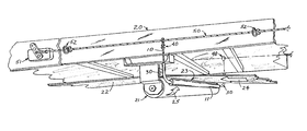
- FIG. 2 is a more detailed elevation sectional view of another embodiment.
- FIG. 1 illustrates a primary pull chord 10 , which spans across a conveyor 20 and parallel to a return idler 21 for the conveyor belt 22 , said primary chord spotted in close proximity upstream to the nip point 23 between the conveyor belt motion 24 and the return idler rotation 25 .
- the free-standing primary pull chord 10 would eventually droop downwards because of thermal variations, or age. As a preventative measure, the primary pull chord 10 is sleeved with a semi-rigid, yet pliable support rod 11 .
- Each end of the primary pull chord 10 is then reeved through a guide 30 rigidly attached to the side of the conveyor 20 , until each end of the support rod 11 rests onto their respective guides 30 .
- Each end of the primary pull chord 10 is terminated by a hoop 40 around a thimble 41 , held in place with one or more cable clips 42 , as viewed in FIG. 2.
- one end of the primary pull chord 10 is rigidly attached to one side of the conveyor by means of fasteners 43 , and the other end of the primary pull chord 10 has a secondary pull chord 50 threaded through the eye of the hoop 40 .
- each end of the secondary pull chord 50 is in turn terminated by a similar hoop 40 , with one end rigidly fastened to one end of the conveyor 20 .
- the secondary pull chord 50 runs longitudinally along the conveyor 20 , laced through strategically located eye-bolts 52 .
- the other end of the secondary pull chord 50 is fastened to a conveyor-disabling safety device 51 at the other end of the conveyor 20 .
- the hoop 40 at each end of the primary pull chord 10 could each be threaded with their own secondary pull chord 50 running longitudinally along each side of the conveyor 20 , said individual secondary pull chords 50 fastened at one end of the conveyor 20 , and the other end of these secondary pull chords 50 fastened to dual conveyor-disabling devices 51 , one on each side at the other end of the conveyor 20 .
- the semi-rigid rod 11 may be encapsulated with a lightweight foamy tube 12 in order to give extra bulkiness to the primary pull chord 10 .
- the guides may be adapted to roller screened- or meshed-guards
- the guides or support rod may be adapted to roller drop-off guards or frames
Landscapes
- Structure Of Belt Conveyors (AREA)
Abstract
In industrial belted conveying systems, it is common to have a pull chord extending longitudinally along the conveyor, sometimes one chord on each side of the conveyor, said chord being attached to a trip mechanism, or safety switch. A number of serious accidents have occurred in the industry due to unprotected nip points at the return idlers under these conveyors. Accidents were the result of these pull chords not being easily accessible for manual activation of the safety features. In this invention, a primary pull chord is placed near the nip point, inserted through guides, and linked to one or more secondary longitudinal pull chord(s). The primary pull chord may be sleeved with a semi-rigid, pliable rod as additional support between the guides. Further, this semi-rigid rod may be encapsulated in a lightweight foamy tube to give it bulkiness. In the event of an inadvertent incident, the primary pull chord is entrained into the nip point, pulling the secondary longitudinal pull chord which then trips the safety switch, automatically disabling the conveyor drive.
Description
- 1. Field of the Invention
- This invention relates generally to novel and advantageous improvements to belted conveyor safety devices. It is common to have a pull chord extending longitudinally along the side of industrial materials handling conveyors, sometimes one chord on each side of the conveyor. These chords are generally rigidly attached at one end, then threaded through the center of eyebolts along the length of the conveyor, and are finally fastened at the other end to a trip mechanism, or safety switch. These devices are un-affectionately known as ‘Dead-Man Switches’.
- 2. Description of the Prior Art
- There are various types of conveyor safety switching mechanisms on the market essentially comprising of a chord or cable operated type. However, all are presently manually-activated, to my knowledge. That is, they need to be pulled or actuated by an operator or attendant.
- A person pulling on this chord activates the switch, which de-energizes the conveyor by opening the electrical circuit to the drive motor, thus stopping the conveyor belt. All are located along the sides of the conveyors.
- A number of serious accidents have occurred in the industry which have resulted in injury, or worse, due to unprotected nip points at the return idlers under belted conveying systems. The nip point is the pressure point between the moving rubber belt and the return idler roller. It is analogous to the double-roller squeezing action of the antiquated wringer-washer. The return idlers are located cross-directionally to the belt travel, on the underside, or belly of the conveyor.
- Extensive guarding, or barriers, could be installed to restrict access underneath these conveying structures while they are in operation. These barriers ultimately become inefficient in terms of safeguarding devices, especially when affecting housekeeping in these areas, because there is a likelihood of:
- the barriers are inevitably opened or removed;
- the guards are not replaced, or;
- the guards are simply left open if they are hinged.
- Tools (such as brooms, rakes, or shovels) and personal loose clothing can become entrained into these nip points. Although longitudinal pull chords and trip mechanisms are meant to be a protective device as a combination, chances are if and while an accident occurs, the casualty does not have the reach, or the thought process, to manually activate the tripping mechanism by pulling the longitudinal chords. Hence, these mechanisms are also not effective safeguarding devices.
- In this invention, a simple, inexpensive, yet efficient device has been developed to minimize the risks of injuries with consideration to housekeeping requirements on the underside of belted conveyors.
- I have found that the inaccessibility to, and the inefficient manual activation of the longitudinal pull chord can be easily overcome.
- In this invention: a primary pull chord length is sleeved with a shorter semi-rigid support rod; this primary pull chord spans in parallel closely upstream of a conveyor return idler nip point; each end of the said pull chord is inserted through guides rigidly attached onto each side of said conveyor; at least one end of the primary pull chord is linked to a secondary pull chord, longitudinal to the conveyor, this secondary pull chord in turn is connected to a conveyor-disabling safety device; and the other end of the primary pull chord, if not attached to another secondary pull chord on the opposite side of the conveyor to the first secondary pull chord, it is then rigidly attached onto that opposite side of the conveyor.
- Additionally, the semi-rigid support rod may be encapsulated in a lightweight foamy tube to give it bulkiness by increasing the surface area.
- In the event of an incident, the primary pull chord, being close to the leading edge of the nip point, is automatically entrained into the nip point. The primary chord in turn draws the secondary longitudinal pull chord, which then trips the safety switch, thus effectively de-energizing the conveyor belt.
- The added bulkiness of the lightweight foamy tube encapsulating the semi-rigid support rod improves the likelihood the primary pull chord will get entrained into the nip if an external force displaces it from its original position.
- Although the intent of this device is to serve as a more efficient means of activation of the tripping mechanism, it is not meant to act as a barrier. If an incident does occur, this device will minimize the extent of the injury. It also serves as a more direct and accessible pull chord even if it is not actually entrained, for one reason or another, into the nip point.
- It is an overall aim of the present invention to provide a conveyor belt nip point protection device.
- It is also an aspect of this invention to provide a more efficient and automatic conveyor-tripping mechanism by providing a direct and accessible pull chord close to the nip point.
- Yet another advantage of this invention is to afford a semi-rigid mechanism that can be reset into place after having been activated.
- Still another aim of the present invention is for a product to be pliable with minimal replacement parts after having gone through the nip point a number of times.
- Finally, one last objective of this invention is to offer a product that can be easily and inexpensively manufactured.
- Other objects and advantages of the present invention may present themselves from the following description when considered with the accompanying drawings.
- FIG. 1 is a partial perspective view of one embodiment, and;
- FIG. 2 is a more detailed elevation sectional view of another embodiment.
- Referring now in more detail and by reference characters to the drawings which designate identical or corresponding practical embodiments of the invention throughout the several views, FIG. 1 illustrates a
primary pull chord 10, which spans across aconveyor 20 and parallel to areturn idler 21 for theconveyor belt 22, said primary chord spotted in close proximity upstream to thenip point 23 between theconveyor belt motion 24 and thereturn idler rotation 25. - The free-standing
primary pull chord 10 would eventually droop downwards because of thermal variations, or age. As a preventative measure, theprimary pull chord 10 is sleeved with a semi-rigid, yet pliable support rod 11. - Each end of the
primary pull chord 10 is then reeved through aguide 30 rigidly attached to the side of theconveyor 20, until each end of the support rod 11 rests onto theirrespective guides 30. - Each end of the
primary pull chord 10 is terminated by ahoop 40 around a thimble 41, held in place with one ormore cable clips 42, as viewed in FIG. 2. - Still as depicted in FIG. 2, one end of the
primary pull chord 10 is rigidly attached to one side of the conveyor by means offasteners 43, and the other end of theprimary pull chord 10 has asecondary pull chord 50 threaded through the eye of thehoop 40. - Likewise, each end of the
secondary pull chord 50 is in turn terminated by asimilar hoop 40, with one end rigidly fastened to one end of theconveyor 20. - Referring back to FIG. 1, the
secondary pull chord 50 runs longitudinally along theconveyor 20, laced through strategically located eye-bolts 52. The other end of thesecondary pull chord 50 is fastened to a conveyor-disablingsafety device 51 at the other end of theconveyor 20. - Alternatively, and symmetrically as visible in FIG. 1, the
hoop 40 at each end of theprimary pull chord 10 could each be threaded with their ownsecondary pull chord 50 running longitudinally along each side of theconveyor 20, said individualsecondary pull chords 50 fastened at one end of theconveyor 20, and the other end of thesesecondary pull chords 50 fastened to dual conveyor-disablingdevices 51, one on each side at the other end of theconveyor 20. - Additionally, the semi-rigid rod 11 may be encapsulated with a
lightweight foamy tube 12 in order to give extra bulkiness to theprimary pull chord 10. - As a sequence: In the event of an incident, the
primary pull chord 10 is entrained into thenip point 23 between theconveyor belt motion 24 and thereturn idler rotation 25, pulling the said primary pull chord's support rod 11 off or out of theguides 30. As theprimary pull chord 10 is being drawn through theguides 30, it tugs on thesecondary pull chord 50, which then trips the conveyor-disablingdevice 51, automatically. - Thus it has been described and illustrated a novel and unique belted conveyor roller nip point protection device which fulfills all of the associated objectives and advantages sought thereof.
- It must be understood, although it is not shown or described, that other appendages may be incorporated to this embodiment with no deviations from the stated embodiment's intended purposes, these appurtenances serving either useful or cosmetic means:
- a) The guides may be adapted to roller screened- or meshed-guards;
- b) The guides or support rod may be adapted to roller drop-off guards or frames;
- c) The same purpose may be achieved if the embodiment is placed on conveyor rollers other than the return idlers.
- It should also be understood that any changes, modifications, variations, substitutions, or other applications or uses will become apparent to those skilled in the art upon consideration of this disclosure and its associated drawings.
- It should further be understood that all changes, modifications, variations, substitutions, or any other applications or uses which do not depart from the scope and spirit of the invention are considered to be covered by the invention which is limited only by the accompanying claims.
Claims (4)
1. A belted conveyor roller nip point automatic protection device comprising of a primary pull chord length, sleeved with a shorter semi-rigid pliable support rod; the primary pull chord spanning across the width of said conveyor, on the upstream side near any one of a conveyor belt's roller nip point; each end of the said primary pull chord is reeved through guides rigidly attached onto each side of said conveyor, until the ends of the support rod are resting onto their respective guides; one end of the primary pull chord is rigidly attached to one side of the conveyor; the other end of the primary pull chord is linked to a secondary pull chord longitudinal to, and on the opposite side of, the conveyor, this secondary pull chord in turn being connected to a conveyor-disabling safety device, for which, if the primary pull chord is inadvertently entrained into the nip point, it in turn draws on the secondary pull chord which then trips the safety device and automatically de-energizes the conveyor drive motor, stopping the belt.
2. A belted conveyor roller nip point automatic protection device comprising of a primary pull chord length, sleeved with a shorter semi-rigid pliable support rod; the primary pull chord spanning across the width of said conveyor, on the upstream side near any one of the conveyor belt's roller nip point; each end of the said primary pull chord is reeved through guides rigidly attached onto each side of said conveyor until the ends of the support rod are resting onto their respective guides; each end of the primary pull chord is linked to a secondary pull chord longitudinal to the conveyor, these secondary pull chords in turn being connected to a conveyor-disabling safety device, for which, if the primary pull chord is inadvertently entrained into the nip point, it in turn draws on the secondary pull chord which then trips the safety device and automatically de-energizes the conveyor drive motor, stopping the belt.
3. A protection device as defined in claim 1 , for which the primary chord semi-rigid pliable support rod is encapsulated with a lightweight foamy tube to give it bulkiness thereby increasing the surface area, and improve the likelihood it will get entrained into the nip if an external force displaces it from its original position.
4. A protection device as defined in claim 2 , for which the primary chord semi-rigid pliable support rod is encapsulated with a lightweight foamy tube to give it bulkiness thereby increasing the surface area, and improve the likelihood it will get entrained into the nip if an external force displaces it from its original position.
Priority Applications (1)
| Application Number | Priority Date | Filing Date | Title |
|---|---|---|---|
| US10/127,458 US6644465B1 (en) | 2002-04-23 | 2002-04-23 | Conveyor roller nip point automatic protection device |
Applications Claiming Priority (1)
| Application Number | Priority Date | Filing Date | Title |
|---|---|---|---|
| US10/127,458 US6644465B1 (en) | 2002-04-23 | 2002-04-23 | Conveyor roller nip point automatic protection device |
Publications (2)
| Publication Number | Publication Date |
|---|---|
| US20030196875A1 true US20030196875A1 (en) | 2003-10-23 |
| US6644465B1 US6644465B1 (en) | 2003-11-11 |
Family
ID=29215271
Family Applications (1)
| Application Number | Title | Priority Date | Filing Date |
|---|---|---|---|
| US10/127,458 Expired - Fee Related US6644465B1 (en) | 2002-04-23 | 2002-04-23 | Conveyor roller nip point automatic protection device |
Country Status (1)
| Country | Link |
|---|---|
| US (1) | US6644465B1 (en) |
Cited By (3)
| Publication number | Priority date | Publication date | Assignee | Title |
|---|---|---|---|---|
| USD622021S1 (en) | 2009-09-25 | 2010-08-17 | Sauder William E | Return roller guard |
| US10836581B2 (en) * | 2016-09-21 | 2020-11-17 | Laitram, L.L.C. | Infeed and outfeed assemblies for a conveyor |
| KR20240095977A (en) * | 2022-12-19 | 2024-06-26 | 현대제철 주식회사 | Apparatus for anti damage of belt conveyor |
Families Citing this family (3)
| Publication number | Priority date | Publication date | Assignee | Title |
|---|---|---|---|---|
| DE102005021627A1 (en) * | 2005-05-06 | 2006-11-16 | Rwe Power Ag | Method for monitoring the band alignment and / or the tape running of a belt conveyor and belt conveyor |
| US10072997B2 (en) | 2015-11-17 | 2018-09-11 | Rockwell Automation Technologies, Inc. | Safety switch with imbalance test |
| US9824841B2 (en) | 2015-11-17 | 2017-11-21 | Rockwell Automation Technologies, Inc. | Safety switch and associated methods |
Family Cites Families (11)
| Publication number | Priority date | Publication date | Assignee | Title |
|---|---|---|---|---|
| US4062442A (en) * | 1974-11-11 | 1977-12-13 | Gebr. Eickhoff, Maschinenfabrik Und Eisengiesserei M.B.H. | Shutoff control apparatus for a conveyor |
| US4079834A (en) * | 1976-02-06 | 1978-03-21 | Aggregates Equipment, Inc. | Conveyor provided with an endless belt tensioning mechanism |
| US4462523A (en) * | 1982-09-29 | 1984-07-31 | Material Control, Inc. | Damaged conveyor belt detector |
| DE3333832A1 (en) * | 1983-09-20 | 1985-04-04 | Fried. Krupp Gmbh, 4300 Essen | Method of detecting metal parts in bulk material of a belt conveyor |
| DE3534307A1 (en) * | 1985-09-26 | 1987-04-16 | Bergwerksverband Gmbh | DEVICE FOR DETERMINING CHAIN TORKS CHAIN-DRIVED EQUIPMENT |
| DE3619528A1 (en) * | 1986-06-10 | 1987-12-17 | Ruhrkohle Ag | Monitoring device for chain conveyor |
| US5347348A (en) * | 1989-09-27 | 1994-09-13 | Canon Kabushiki Kaisha | Image fixing apparatus with detector for detecting movement of endless belt |
| DE69124117D1 (en) * | 1990-10-23 | 1997-02-20 | Tasman Eng Pty Ltd | DEVICE FOR CORRECTING CROSS DEVIATIONS OF A CONVEYOR BELT |
| US5984083A (en) * | 1997-03-10 | 1999-11-16 | Dorner Mfg. Corp. | Conveyor belt tensioning mechanism utilizing a manually operated cam-type tool |
| US6131727A (en) * | 1998-06-10 | 2000-10-17 | Nelson; David W. | Conveyor belt monitor |
| SE9903134L (en) * | 1999-09-03 | 2000-12-11 | Svedala Trellex Ab | Conveyor Control |
-
2002
- 2002-04-23 US US10/127,458 patent/US6644465B1/en not_active Expired - Fee Related
Cited By (5)
| Publication number | Priority date | Publication date | Assignee | Title |
|---|---|---|---|---|
| USD622021S1 (en) | 2009-09-25 | 2010-08-17 | Sauder William E | Return roller guard |
| US10836581B2 (en) * | 2016-09-21 | 2020-11-17 | Laitram, L.L.C. | Infeed and outfeed assemblies for a conveyor |
| US11332318B2 (en) | 2016-09-21 | 2022-05-17 | Laitram, L.L.C. | Infeed and outfeed assemblies for a conveyor |
| KR20240095977A (en) * | 2022-12-19 | 2024-06-26 | 현대제철 주식회사 | Apparatus for anti damage of belt conveyor |
| KR102843936B1 (en) | 2022-12-19 | 2025-08-07 | 현대제철 주식회사 | Apparatus for anti damage of belt conveyor |
Also Published As
| Publication number | Publication date |
|---|---|
| US6644465B1 (en) | 2003-11-11 |
Similar Documents
| Publication | Publication Date | Title |
|---|---|---|
| US6644465B1 (en) | Conveyor roller nip point automatic protection device | |
| AU706254B2 (en) | Article combiner | |
| US3835977A (en) | Handrail guard | |
| US5009307A (en) | Safety device for conveyor systems | |
| IE44527B1 (en) | Machine for treating bags containing city solid wastes | |
| CA2380585C (en) | Conveyor roller nip point automatic protection device | |
| DE69000887T2 (en) | PERSONALIZED CONVEYOR WITH STAIR SPINDLE DEFLECTOR. | |
| US20210403243A1 (en) | Support station, belt conveyor and method of manufacturing such a support station | |
| JP2002017325A (en) | Apparatus for cutting vegetable and fruit | |
| CA1102735A (en) | Jam clearance mechanism for a traveling distributor in a collating system | |
| US6536559B1 (en) | Goods lift | |
| SE8500910D0 (en) | DEVELOPMENT AND / OR INPUT OF SECURITIES | |
| KR880012461A (en) | Long item handling unit with ejector | |
| SE447563B (en) | PORTABLE DRIVE DEVICE WITH A MOTOR DRIVE DRIVE ROLL OR SIMILAR FOR CO-OPERATION WITH A TIRE, A LINE, A WIRE, A CHAIN OR LIKE | |
| ATE109105T1 (en) | CONVEYING DEVICE, PARTICULARLY FOR CONVEYING CONCRETE AND BULK MATERIAL. | |
| US5390760A (en) | Safety guard for scissor lift | |
| JPH06192923A (en) | Apparatus for moving spinning container | |
| IT1275511B (en) | DEVICE FOR THE TRANSPORT OF A VESSEL BETWEEN A MACHINE FOR FILANDA PROVIDING CARDA TAPE, FOR EXAMPLE, CARDA, IRONING, AND A MACHINE FOR FILANDA FEEDING WITH CARDA TAPE, FOR EXAMPLE IRONING, FILATOIO | |
| KR920700799A (en) | Device for conveying the workpiece | |
| US3209703A (en) | Ski lift safety device | |
| US1924899A (en) | Brake mechanism for conveyers | |
| US2755909A (en) | Automatic check stand | |
| Giraud et al. | Belt conveyor safety | |
| WO2015198274A1 (en) | Conveyor | |
| US4464159A (en) | Shop towel folder |
Legal Events
| Date | Code | Title | Description |
|---|---|---|---|
| REMI | Maintenance fee reminder mailed | ||
| LAPS | Lapse for failure to pay maintenance fees | ||
| LAPS | Lapse for failure to pay maintenance fees |
Free format text: PATENT EXPIRED FOR FAILURE TO PAY MAINTENANCE FEES (ORIGINAL EVENT CODE: EXP.); ENTITY STATUS OF PATENT OWNER: SMALL ENTITY |
|
| STCH | Information on status: patent discontinuation |
Free format text: PATENT EXPIRED DUE TO NONPAYMENT OF MAINTENANCE FEES UNDER 37 CFR 1.362 |
|
| FP | Lapsed due to failure to pay maintenance fee |
Effective date: 20071111 |