US20030196855A1 - Ladder accessory holder - Google Patents
Ladder accessory holder Download PDFInfo
- Publication number
- US20030196855A1 US20030196855A1 US10/443,322 US44332203A US2003196855A1 US 20030196855 A1 US20030196855 A1 US 20030196855A1 US 44332203 A US44332203 A US 44332203A US 2003196855 A1 US2003196855 A1 US 2003196855A1
- Authority
- US
- United States
- Prior art keywords
- engagement member
- ladder
- lower engagement
- spring
- rungs
- Prior art date
- Legal status (The legal status is an assumption and is not a legal conclusion. Google has not performed a legal analysis and makes no representation as to the accuracy of the status listed.)
- Granted
Links
- 239000003973 paint Substances 0.000 claims description 5
- 230000009194 climbing Effects 0.000 description 2
- 230000007812 deficiency Effects 0.000 description 1
- 230000005484 gravity Effects 0.000 description 1
- 230000000284 resting effect Effects 0.000 description 1
Images


Classifications
-
- E—FIXED CONSTRUCTIONS
- E06—DOORS, WINDOWS, SHUTTERS, OR ROLLER BLINDS IN GENERAL; LADDERS
- E06C—LADDERS
- E06C7/00—Component parts, supporting parts, or accessories
- E06C7/14—Holders for pails or other equipment on or for ladders
Definitions
- the present application is a continuation-in-part of co-pending U.S. Pat. No. application Ser. No. 09/854,808, filed May 14, 2001.
- the present application relates to a device adapted to be removably and securely attached between the rungs of a ladder, in order to hold a bucket or other object.
- a number of U.S. patents disclose devices for attaching to ladders in order to support buckets. Such devices generally fall into two types.
- a first type is attached to the rail of the ladder, as illustrated in U.S. Pat. Nos. D313,169; 4,776,550; and 5,305,977. These devices share a common deficiency in that the device cannot be easily moved up the ladder as the painter climbs the ladder without completely detaching the device from the rail, because the ladder rungs prevent movement of the device along the rail.
- a second type is attached to a rung of the ladder, as illustrated in U.S. Pat. Nos. D266,964; D393,413; 3,895,772; 5,305,977; and 5,716,034.
- U.S. Pat. No. 5,305,977 these patents do not disclose a means for securely attaching the bucket to the ladder rung, i.e., they all rely on gravity to keep the bucket attached to the rung.
- U.S. Pat. No. 5,305,977 discloses a hook for engaging a ladder rung and a spring for securing the hook in place; however, the design would allow the hook to rotate around the rung under the moment of inertia of the paint bucket.
- a principal object and advantage of the present invention is that is securely attachable to each of two adjacent rungs of a ladder, and therefore cannot move either vertically or horizontally.
- Another principle object and advantage of the present invention is that it is easily detachable from the ladder rungs so that the person climbing the ladder may move the apparatus to ladder rungs further up the ladder.
- Another principle object and advantage of the present invention is that it is spring-biased between adjacent ladder rungs in such a way that it can be removed and moved along the ladder with only one hand.
- Another object and advantage of the present invention is that it may include a pivoting arm which can be used to attach a variety of accessories, such as a bucket holder, bucket, hook, and gripper.
- Another object and advantage of the present invention is that it may include a footrest attached to the apparatus.
- FIG. 1 is a perspective view of a ladder with a first embodiment of the invention attached thereto.
- FIG. 2 is the same as FIG. 1, but with a second embodiment of the invention attached thereto.
- FIG. 3 is a perspective view of a first embodiment of the invention, with ladder rungs shown in phantom.
- FIG. 4 is a perspective view of a second embodiment of the invention, with ladder rungs shown in phantom.
- FIGS. 5 A- 5 D are perspective views of various accessories that may be part of the invention.
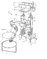
- FIG. 6 is a perspective view of a third embodiment of the present invention, with the ladder shown in phantom.
- FIG. 7 is a detail of the third embodiment of FIG. 6.
- FIG. 8 is similar to FIG. 6, but without the ladder shown in phantom.
- FIGS. 1 and 2 show a ladder L leaning against a wall W.
- the ladder L has rungs R and side rails S.
- the terms “upper” and “lower” shall refer to orientations in which the invention is attached to a ladder which is resting more or less upright against a wall or other support.
- a first embodiment of the apparatus 10 of the present invention is shown attached to the ladder L in FIG. 1.
- the apparatus 10 attaches between the rungs R by means of engagement members 12 that contact adjacent sides RA of the rungs R.
- a second embodiment 110 of the present invention is shown attached to the ladder in FIG. 2.
- the apparatus 110 attaches between the rungs R by means of engagement members 112 that contact non-adjacent sides RO of the rungs R.
- the apparatus 10 further comprises a lower engagement member 14 adapted to engage ladder rung RI and an upper engagement member 16 adapted to engage adjacent rung R 2 .
- the apparatus 10 also comprises a spring 18 biasing the lower engagement member 14 and the upper engagement member 16 against the rungs R 1 , R 2 .
- the lower engagement member 14 and upper engagement member 16 preferably comprise U-shaped channels 20 adapted to contact the ladder rungs on the adjacent sides RA.
- the spring 18 contacts one of the engagement members 14 , 16 .
- a ram 26 then makes contact with the other engagement member, biased by the spring 18 .
- the ram 26 and spring 18 are enclosed within a guide 22 having a central core 24 , with the ram 26 reciprocating within the guide 22 .
- a second guide 26 , ram 22 , and spring 18 may be employed, as shown in FIG. 3, or a single guide 26 , ram 22 , and spring 18 may be used, as shown in FIG. 8.
- the apparatus 110 further comprises a lower engagement member 114 adapted to engage ladder rung R 1 and an upper engagement member 116 adapted to engage adjacent rung R 2 .
- the apparatus 110 also comprises a spring 118 biasing the lower engagement member 114 and the upper engagement member 116 against the rungs R 1 , R 2 .
- the lower engagement member 114 and upper engagement member 116 preferably comprise hooks 120 adapted to contact the ladder rungs on the opposite sides RO.
- the spring 118 contacts one of the engagement members 114 , 116 .
- a ram 126 then makes contact with the other engagement member, biased by the spring 118 .
- the ram 126 and spring 118 are enclosed within a guide 122 having a central core 124 , with the ram 126 reciprocating within the guide 122 .
- a second guide 126 , ram 122 , and spring 118 may be employed, as shown in FIG. 4.
- a frame 30 may be interposed vertically between the lower engagement member 14 , 114 and the upper engagement member 16 , 116 . If more than one guide 22 , 122 is used, the frame 30 serves to connect the guides together for parallel movement. The frame may also be used to assist in pulling the members 114 , 116 apart in the second embodiment.
- An arm 40 may be pivotally attached to the frame 30 .
- a variety of interchangeable accessories 50 may be attached to the arm 40 .
- FIGS. 5 a - 5 d illustrate some of these accessories: a tool holder 52 ; a bucket 54 , a hook 56 , or a gripper 58 .
- Other accessories are possible.
- FIGS. 6 - 8 A third embodiment of the invention is shown in FIGS. 6 - 8 .
- the apparatus 210 further comprises a lower engagement member 214 adapted to engage ladder rung R 2 and an upper engagement member 216 adapted to engage adjacent rung R 1 .
- the apparatus 210 also comprises a spring 218 biasing the lower engagement member 214 and the upper engagement member 216 against the rungs R 1 , R 2 .
- the lower engagement member 214 and upper engagement member 216 preferably comprise U-shaped channels 220 adapted to contact the ladder rungs on the adjacent sides RA.
- the spring 218 contacts one of the engagement members 214 , 216 .
- a ram 226 then makes contact with the other engagement member, biased by the spring 218 .
- the ram 226 and spring 218 are enclosed within a guide 222 having a central core 224 , with the ram 226 reciprocating within the guide 222 .
- a frame 230 may be interposed vertically between the lower engagement member 214 and the upper engagement member 216 .
- the frame 230 is mounted on the guide 222 , as shown in FIG. 7.
- An arm 240 may be pivotally attached to the frame 230 .
- a variety of interchangeable accessories 250 may be attached to the arm 240 .
- FIGS. 6 and 8 illustrate some of these accessories: a bucket holder 252 and a paint tray holder 2 . Other accessories are possible.
- the arm 240 is removably attached to the frame 230 .
- the arm 240 may be attached to the frame 230 by a cotter pin 260 . Any other attachment is also envisioned, such as screws, nuts, bolts, or other fasteners.
- a second arm 240 may also be attached to the frame 230 .
- the third embodiment 210 also preferably comprises a footrest 270 attached to the lower engagement member 214 , as shown in FIGS. 6 - 8 .
- the footrest 270 is most preferably attached to the lower engagement member 214 so that the footrest 270 is substantially perpendicular to the lower engagement member 214 .
- a second footrest 270 may be added on the side of the guide 222 opposite the first footrest 270 .
- the footrests 270 allow a person to have a more secure, more restful, stance on the ladder.
Landscapes
- Engineering & Computer Science (AREA)
- Mechanical Engineering (AREA)
- Ladders (AREA)
Abstract
An apparatus for attachment to the rungs of a ladder to securely hold a bucket and other accessories. The apparatus is readily detachable from the ladder rungs for movement along the ladder. The apparatus includes engagement members for gripping the ladder rungs and a spring for biasing the engagement members against the ladder rungs. The apparatus may have a pivotable arm to which a variety of accessories may be attached.
Description
- The present application is a continuation-in-part of co-pending U.S. Pat. No. application Ser. No. 09/854,808, filed May 14, 2001. The present application relates to a device adapted to be removably and securely attached between the rungs of a ladder, in order to hold a bucket or other object.
- A number of U.S. patents disclose devices for attaching to ladders in order to support buckets. Such devices generally fall into two types.
- A first type is attached to the rail of the ladder, as illustrated in U.S. Pat. Nos. D313,169; 4,776,550; and 5,305,977. These devices share a common deficiency in that the device cannot be easily moved up the ladder as the painter climbs the ladder without completely detaching the device from the rail, because the ladder rungs prevent movement of the device along the rail.
- A second type is attached to a rung of the ladder, as illustrated in U.S. Pat. Nos. D266,964; D393,413; 3,895,772; 5,305,977; and 5,716,034. However, with the exception of U.S. Pat. No. 5,305,977, these patents do not disclose a means for securely attaching the bucket to the ladder rung, i.e., they all rely on gravity to keep the bucket attached to the rung. U.S. Pat. No. 5,305,977 discloses a hook for engaging a ladder rung and a spring for securing the hook in place; however, the design would allow the hook to rotate around the rung under the moment of inertia of the paint bucket.
- There is a need for a device that can be easily attached to a ladder to hold a bucket and other attachments, that can be secured in place, and that can be easily removed from the ladder to move along the ladder with the painter or other person climbing the ladder.
- Apparatus for attachment to the rungs of a ladder for securely holding a bucket and other accessories, the apparatus being readily detachable from the ladder rungs for movement along the ladder, the apparatus comprising:
- a) a lower engagement member adapted to engage a ladder rung;
- b) an upper engagement member adapted to engage an adjacent ladder rung; and
- c) an spring biasing the lower engagement member and upper engagement member against the respective ladder rungs.
- A principal object and advantage of the present invention is that is securely attachable to each of two adjacent rungs of a ladder, and therefore cannot move either vertically or horizontally.
- Another principle object and advantage of the present invention is that it is easily detachable from the ladder rungs so that the person climbing the ladder may move the apparatus to ladder rungs further up the ladder.
- Another principle object and advantage of the present invention is that it is spring-biased between adjacent ladder rungs in such a way that it can be removed and moved along the ladder with only one hand.
- Another object and advantage of the present invention is that it may include a pivoting arm which can be used to attach a variety of accessories, such as a bucket holder, bucket, hook, and gripper.
- Another object and advantage of the present invention is that it may include a footrest attached to the apparatus.
- FIG. 1 is a perspective view of a ladder with a first embodiment of the invention attached thereto.
- FIG. 2 is the same as FIG. 1, but with a second embodiment of the invention attached thereto.
- FIG. 3 is a perspective view of a first embodiment of the invention, with ladder rungs shown in phantom.
- FIG. 4 is a perspective view of a second embodiment of the invention, with ladder rungs shown in phantom.
- FIGS. 5A-5D are perspective views of various accessories that may be part of the invention.
- FIG. 6 is a perspective view of a third embodiment of the present invention, with the ladder shown in phantom.
- FIG. 7 is a detail of the third embodiment of FIG. 6.
- FIG. 8 is similar to FIG. 6, but without the ladder shown in phantom.
- FIGS. 1 and 2 show a ladder L leaning against a wall W. The ladder L has rungs R and side rails S.
- In this Detailed Description, the terms “upper” and “lower” shall refer to orientations in which the invention is attached to a ladder which is resting more or less upright against a wall or other support.
- A first embodiment of the
apparatus 10 of the present invention is shown attached to the ladder L in FIG. 1. In the first embodiment, theapparatus 10 attaches between the rungs R by means ofengagement members 12 that contact adjacent sides RA of the rungs R. - A
second embodiment 110 of the present invention is shown attached to the ladder in FIG. 2. In the second embodiment, theapparatus 110 attaches between the rungs R by means ofengagement members 112 that contact non-adjacent sides RO of the rungs R. - Details of the
first embodiment 10 are shown in FIG. 3. Theapparatus 10 further comprises a lower engagement member 14 adapted to engage ladder rung RI and an upper engagement member 16 adapted to engage adjacent rung R2. Theapparatus 10 also comprises aspring 18 biasing the lower engagement member 14 and the upper engagement member 16 against the rungs R1, R2. - The lower engagement member 14 and upper engagement member 16 preferably comprise U-shaped
channels 20 adapted to contact the ladder rungs on the adjacent sides RA. - Preferably, the
spring 18 contacts one of the engagement members 14, 16. Aram 26 then makes contact with the other engagement member, biased by thespring 18. Most preferably, theram 26 andspring 18 are enclosed within aguide 22 having acentral core 24, with theram 26 reciprocating within theguide 22. Asecond guide 26,ram 22, andspring 18 may be employed, as shown in FIG. 3, or asingle guide 26,ram 22, andspring 18 may be used, as shown in FIG. 8. - It will be seen that, to attach the
apparatus 10 to the rungs R, it is merely necessary to compress thespring 18, by pushing the lower engagement member 14 toward the upper engagement member 16. One of the members 14, 16 is then slid against a rung, and the spring tension is released, allowing the other member 14, 16 to slide against the adjacent rung. To facilitate this operation, one of the members 14, 16 may have ahandle 28. - Turning to FIG. 4, details of the second embodiment are illustrated. The
apparatus 110 further comprises a lower engagement member 114 adapted to engage ladder rung R1 and an upper engagement member 116 adapted to engage adjacent rung R2. Theapparatus 110 also comprises aspring 118 biasing the lower engagement member 114 and the upper engagement member 116 against the rungs R1, R2. - The lower engagement member 114 and upper engagement member 116 preferably comprise
hooks 120 adapted to contact the ladder rungs on the opposite sides RO. - Preferably, the
spring 118 contacts one of the engagement members 114, 116. Aram 126 then makes contact with the other engagement member, biased by thespring 118. Most preferably, theram 126 andspring 118 are enclosed within aguide 122 having acentral core 124, with theram 126 reciprocating within theguide 122. Asecond guide 126,ram 122, andspring 118 may be employed, as shown in FIG. 4. - It will be seen that, to attach the
apparatus 110 to the rungs R, it is merely necessary to expand thespring 118, by hooking one of the members 114, under a rung, then pulling the upper engagement member 116 away from the lower engagement member 114. The spring tension is released, allowing the other member 116 to slide over the adjacent rung. To facilitate this operation, ahandle 128 may be attached to one of the members 114, 116. - In each embodiment a
frame 30 may be interposed vertically between the lower engagement member 14, 114 and the upper engagement member 16, 116. If more than oneguide frame 30 serves to connect the guides together for parallel movement. The frame may also be used to assist in pulling the members 114, 116 apart in the second embodiment. - An
arm 40 may be pivotally attached to theframe 30. A variety of interchangeable accessories 50 may be attached to thearm 40. FIGS. 5a-5 d illustrate some of these accessories: atool holder 52; abucket 54, ahook 56, or agripper 58. Other accessories are possible. - A third embodiment of the invention is shown in FIGS. 6-8.
- Details of the
third embodiment 10 are shown in FIG. 6. Theapparatus 210 further comprises a lower engagement member 214 adapted to engage ladder rung R2 and an upper engagement member 216 adapted to engage adjacent rung R1. Theapparatus 210 also comprises aspring 218 biasing the lower engagement member 214 and the upper engagement member 216 against the rungs R1, R2. - The lower engagement member 214 and upper engagement member 216 preferably comprise
U-shaped channels 220 adapted to contact the ladder rungs on the adjacent sides RA. - Preferably, the
spring 218 contacts one of the engagement members 214, 216. Aram 226 then makes contact with the other engagement member, biased by thespring 218. Most preferably, theram 226 andspring 218 are enclosed within aguide 222 having a central core 224, with theram 226 reciprocating within theguide 222. - It will be seen that, to attach the
apparatus 210 to the rungs R, it is merely necessary to compress thespring 218, by pushing downwardly the lower engagement member 214 onto rung R2 withhandle 228. Then, upper member 216 is then slid underneath rung R1, and the spring tension is released, allowing the members 214, 216 to lock in place. - A
frame 230 may be interposed vertically between the lower engagement member 214 and the upper engagement member 216. Preferably, theframe 230 is mounted on theguide 222, as shown in FIG. 7. - An
arm 240 may be pivotally attached to theframe 230. A variety of interchangeable accessories 250 may be attached to thearm 240. FIGS. 6 and 8 illustrate some of these accessories: abucket holder 252 and a paint tray holder 2. Other accessories are possible. - Most preferably, the
arm 240 is removably attached to theframe 230. As shown in FIG. 7, thearm 240 may be attached to theframe 230 by acotter pin 260. Any other attachment is also envisioned, such as screws, nuts, bolts, or other fasteners. Asecond arm 240 may also be attached to theframe 230. - The
third embodiment 210 also preferably comprises afootrest 270 attached to the lower engagement member 214, as shown in FIGS. 6-8. Thefootrest 270 is most preferably attached to the lower engagement member 214 so that thefootrest 270 is substantially perpendicular to the lower engagement member 214. Asecond footrest 270 may be added on the side of theguide 222 opposite thefirst footrest 270. Thefootrests 270 allow a person to have a more secure, more restful, stance on the ladder. - The present invention may be embodied in other specific forms without departing from the spirit or essential attributes thereof, and it is therefore desired that the present embodiment be considered in all respects as illustrative and not restrictive, reference being made to the appended claims rather than to the foregoing description to indicate the scope of the invention.
Claims (23)
1. Apparatus for attachment to the rungs of a ladder for securely holding a bucket and other accessories, the apparatus being readily detachable from the ladder rungs for movement along the ladder, the apparatus comprising:
(a) a lower engagement member adapted to engage a ladder rung;
(b) an upper engagement member adapted to engage an adjacent ladder rung;
(c) a spring biasing the lower engagement member and upper engagement member against the respective ladder rungs; and
(d) a frame interposed vertically between the lower engagement member and the upper engagement member and an arm pivotally attached to the frame.
2. The apparatus of claim 1 , wherein the lower engagement member and upper engagement member each further comprise a substantially U-shaped channel adapted to contact the ladder rungs on adjacent sides of the ladder rungs.
3. The apparatus of claim 1 , wherein the lower engagement member and upper engagement member each further comprise hooks adapted to contact the ladder rungs on nonadjacent sides of the ladder rungs.
4. The apparatus of claim 1 , further comprising a guide engaging the lower engagement member, the spring being contained within the guide, and a ram reciprocating within the guide and biased by the spring.
5. The apparatus of claim 1 , further comprising a footrest attached to the lower engagement member, the footrest being substantially perpendicular to the lower engagement member.
6. The apparatus of claim 1 , further comprising a second guide engaging the lower engagement member, a second spring contained within the guide, and a second ram reciprocating within the guide and biased by the spring.
7. The apparatus of claim 1 , further comprising accessories attachable to the arm.
8. The apparatus of claim 7 , wherein the accessories are selected from the group consisting of: a bucket holder, a bucket, a hook, a gripper, and a paint tray.
9. The apparatus of claim 1 , wherein the arm is detachable from the frame.
10. Apparatus for attachment to the rungs of a ladder for securely holding a bucket and other accessories, the apparatus being readily detachable from the ladder rungs for movement along the ladder, the apparatus comprising:
(a) a lower engagement member adapted to engage a ladder rung;
(b) an upper engagement member adapted to engage an adjacent ladder rung;
(c) a spring biasing the lower engagement member and upper engagement member against the respective ladder rungs wherein the lower engagement member and upper engagement member each further comprise a substantially U-shaped channel adapted to contact the ladder rungs on adjacent sides of the ladder rungs; and
(d) a frame interposed vertically between the lower engagement member and the upper engagement member and an arm pivotally attached to the frame.
11. The apparatus of claim 10 , further comprising a guide engaging the lower engagement member, the spring being contained within the guide, and a ram reciprocating within the guide and biased by the spring.
12. The apparatus of claim 10 , further comprising a footrest attached to the lower engagement member, the footrest being substantially perpendicular to the lower engagement member.
13. The apparatus of claim 10 , further comprising a second guide engaging the lower engagement member, a second spring contained within the guide, and a ram reciprocating within the guide and biased by the spring.
14. The apparatus of claim 10 , further comprising accessories attachable to the arm.
15. The apparatus of claim 14 , wherein the accessories are selected from the group consisting: of a bucket holder, a bucket, a hook, a gripper, and a paint tray.
16. The apparatus of claim 10 , wherein the arm is detachable from the frame.
17. Apparatus for attachment to the rungs of a ladder for securely holding a bucket and other accessories, the apparatus being readily detachable from the ladder rungs for movement along the ladder, the apparatus comprising:
(a) a lower engagement member adapted to engage a ladder rung;
(b) an upper engagement member adapted to engage an adjacent ladder rung;
(c) a spring biasing the lower engagement member and upper engagement member against the respective ladder rungs wherein the lower engagement member and upper engagement member each further comprise hooks adapted to contact the ladder rungs on non-adjacent sides of the ladder rungs; and
(d) a frame interposed vertically between the lower engagement member and the upper engagement member and an arm pivotally attached to the frame.
18. The apparatus of claim 17 , further comprising a guide engaging the lower engagement member, the spring being contained within the guide, and a ram reciprocating within the guide and biased by the spring.
19. The apparatus of claim 17 , further comprising a footrest attached to the lower engagement member, the footrest being substantially perpendicular to the lower engagement member.
20. The apparatus of claim 17 , further comprising a second guide engaging the lower engagement member, a second spring contained within the guide, and a ram reciprocating within the guide and biased by the spring.
21. The apparatus of claim 17 , further comprising accessories attachable to the arm.
22. The apparatus of claim 21 , wherein the accessories are selected from the group consisting: of a bucket holder, a bucket, a hook, a gripper, and a paint tray.
23. The apparatus of claim 17 , wherein the arm is detachable from the frame.
Priority Applications (1)
| Application Number | Priority Date | Filing Date | Title |
|---|---|---|---|
| US10/443,322 US6848540B2 (en) | 2001-05-14 | 2003-05-21 | Ladder accessory holder |
Applications Claiming Priority (2)
| Application Number | Priority Date | Filing Date | Title |
|---|---|---|---|
| US09/854,808 US20020166724A1 (en) | 2001-05-14 | 2001-05-14 | Ladder bucket holder |
| US10/443,322 US6848540B2 (en) | 2001-05-14 | 2003-05-21 | Ladder accessory holder |
Related Parent Applications (1)
| Application Number | Title | Priority Date | Filing Date |
|---|---|---|---|
| US09/854,808 Continuation-In-Part US20020166724A1 (en) | 2001-05-14 | 2001-05-14 | Ladder bucket holder |
Publications (2)
| Publication Number | Publication Date |
|---|---|
| US20030196855A1 true US20030196855A1 (en) | 2003-10-23 |
| US6848540B2 US6848540B2 (en) | 2005-02-01 |
Family
ID=46282362
Family Applications (1)
| Application Number | Title | Priority Date | Filing Date |
|---|---|---|---|
| US10/443,322 Expired - Fee Related US6848540B2 (en) | 2001-05-14 | 2003-05-21 | Ladder accessory holder |
Country Status (1)
| Country | Link |
|---|---|
| US (1) | US6848540B2 (en) |
Cited By (15)
| Publication number | Priority date | Publication date | Assignee | Title |
|---|---|---|---|---|
| AT413578B (en) * | 2003-12-09 | 2006-03-15 | Moser Johann Ing | HOLDING A STORAGE AID |
| US20070193829A1 (en) * | 2006-02-21 | 2007-08-23 | Werner Co. | Pipe tradesman's ladder and method |
| US20110079467A1 (en) * | 2009-10-05 | 2011-04-07 | Mares Ronald E | Side of ladder accessory |
| USD661406S1 (en) * | 2011-06-17 | 2012-06-05 | Madison Electric Products, Inc. | Attachment arm for supporting an object on a step ladder |
| US20140131137A1 (en) * | 2012-11-15 | 2014-05-15 | Irwin Jay Bassett | Tree-mounted hunting stand with modular functionality |
| KR101398453B1 (en) * | 2013-11-25 | 2014-06-27 | 황연하 | foldable ladder type structure with Capable of detaching and attaching |
| US20140311828A1 (en) * | 2012-11-15 | 2014-10-23 | Irwin Jay Bassett | Modular tree-mountable hunting stand |
| US20170205023A1 (en) * | 2015-11-24 | 2017-07-20 | Fourth Arrow, LLC | Utility Mount with Removable Adjustable Ball Joint and Device Mount |
| EP3202539A1 (en) * | 2016-02-03 | 2017-08-09 | Ekso Bionics, Inc. | Tool arm mount for aerial work platform |
| GB2563374A (en) * | 2017-04-05 | 2018-12-19 | R D S Innovations Ltd | Ladder safety device |
| US10474013B2 (en) * | 2015-11-24 | 2019-11-12 | Fourth Arrow, LLC | Utility mount with removable adjustable ball joint and device mount |
| US10473151B2 (en) * | 2015-11-24 | 2019-11-12 | Fourth Arrow, LLC | Utility mount with removable adjustable ball joint and device mount |
| US20210033244A1 (en) * | 2019-07-30 | 2021-02-04 | Fourth Arrow, LLC | Mount for tree stand |
| US11219997B1 (en) * | 2020-12-02 | 2022-01-11 | Artur Carvalho | Portable wall supported tool holder |
| US20250346064A1 (en) * | 2024-05-07 | 2025-11-13 | David Kropacek | Paint tray with locking arm support |
Families Citing this family (12)
| Publication number | Priority date | Publication date | Assignee | Title |
|---|---|---|---|---|
| US7077238B2 (en) * | 2003-09-13 | 2006-07-18 | Butler David C | Ladder caddy |
| US20050067361A1 (en) * | 2003-09-26 | 2005-03-31 | Waymire Douglas E. | Work Platform tool & material shelf |
| US7845469B1 (en) * | 2006-07-20 | 2010-12-07 | Butler David C | Ladder caddy |
| US8033362B1 (en) * | 2007-07-19 | 2011-10-11 | Cull Gerald R | Paint tray caddy for extension ladders and method of use thereof |
| US20090032662A1 (en) * | 2007-08-05 | 2009-02-05 | Parrott Donnette W | Tray system for stepladders or the like, and method therefore |
| US20130112502A1 (en) * | 2011-11-08 | 2013-05-09 | Linda OLIVER | Ladder Caddy |
| US20130200230A1 (en) * | 2012-02-08 | 2013-08-08 | Carl Christiansen | Adjustable step ladder paint bucket holder |
| US9809415B2 (en) * | 2014-06-10 | 2017-11-07 | Textron Innovations Inc. | Mounting assembly for mounting a sheave roller to a cable tray |
| US9810022B1 (en) * | 2014-10-11 | 2017-11-07 | Lawrence Ayala | Tool holder support |
| EP3408487B1 (en) * | 2016-01-27 | 2021-03-03 | The Lacket Company PTY Ltd | Device for stabilising a ladder, and a ladder |
| US11383549B2 (en) * | 2020-01-31 | 2022-07-12 | Mark Turner | Painting tool holder |
| US20240344396A1 (en) * | 2023-04-11 | 2024-10-17 | Tom Cleland | Suspension assemblies for suspending containers and methods of use |
Citations (3)
| Publication number | Priority date | Publication date | Assignee | Title |
|---|---|---|---|---|
| US2439430A (en) * | 1946-05-20 | 1948-04-13 | George K Hurd | Hook attachment for ladders |
| US4433822A (en) * | 1981-08-18 | 1984-02-28 | Nurmi Caggiano | Paint can receptacle and the like |
| US4450935A (en) * | 1982-12-27 | 1984-05-29 | Gustavus David C | Portable adjustable roof platform |
Family Cites Families (16)
| Publication number | Priority date | Publication date | Assignee | Title |
|---|---|---|---|---|
| US3895772A (en) | 1974-02-25 | 1975-07-22 | Erling Ellingson | Device for supporting a bucket on a ladder |
| US4017047A (en) | 1976-05-21 | 1977-04-12 | C. T. Inc. | Quick-release roller attachment for supporting a rope or hose and the like on an aerial ladder |
| DE2851987C2 (en) | 1978-12-01 | 1986-07-24 | Nikolaus Adalbert 7730 Villingen-Schwenningen Kümmerlin | Support device for ladders |
| USD266964S (en) | 1980-07-28 | 1982-11-16 | Rasheed Abdullah K | Combined ladder bucket and brush holder |
| ATE72874T1 (en) | 1986-01-24 | 1992-03-15 | John Colin Campbell | SEATING ON A LADDER. |
| DE3704391A1 (en) | 1987-01-30 | 1988-08-11 | Karl Eberl | Ladder-securing means |
| US4776550A (en) | 1987-08-06 | 1988-10-11 | Storey Willie J | Paint bucket holder for ladder |
| USD313169S (en) | 1988-03-21 | 1990-12-25 | Scott Randy E | Ladder rail attached paint bucket holder |
| DE4041428A1 (en) | 1989-12-27 | 1991-07-04 | Paul Eberl | Ladder stability securing mechanism - has sprung telescopic bracket with hook, whose holders engage two adjacent rungs |
| US5305977A (en) | 1992-05-08 | 1994-04-26 | Roth Alfred C | Ladder paint bucket holders |
| US5421428A (en) | 1993-11-01 | 1995-06-06 | Ingles; Jack G. | Ladder guard |
| US5716034A (en) | 1994-06-03 | 1998-02-10 | Unkefer; Lynn F. | Apparatus for hanging a bucket on a ladder |
| US5431249A (en) | 1994-07-21 | 1995-07-11 | Richard A. Tredup | Universally adjustable support platform for ladders |
| USD393413S (en) | 1997-03-24 | 1998-04-14 | Brown Robert A | Ladder paint bucket hook |
| US6250595B1 (en) | 1999-10-27 | 2001-06-26 | Francis Campbell | Paint bucket holder |
| US6241204B1 (en) | 2000-04-12 | 2001-06-05 | Michael L. Bermes | Paint bucket holder for hollow rung ladders |
-
2003
- 2003-05-21 US US10/443,322 patent/US6848540B2/en not_active Expired - Fee Related
Patent Citations (3)
| Publication number | Priority date | Publication date | Assignee | Title |
|---|---|---|---|---|
| US2439430A (en) * | 1946-05-20 | 1948-04-13 | George K Hurd | Hook attachment for ladders |
| US4433822A (en) * | 1981-08-18 | 1984-02-28 | Nurmi Caggiano | Paint can receptacle and the like |
| US4450935A (en) * | 1982-12-27 | 1984-05-29 | Gustavus David C | Portable adjustable roof platform |
Cited By (21)
| Publication number | Priority date | Publication date | Assignee | Title |
|---|---|---|---|---|
| AT413578B (en) * | 2003-12-09 | 2006-03-15 | Moser Johann Ing | HOLDING A STORAGE AID |
| US10208538B2 (en) * | 2006-02-21 | 2019-02-19 | Werner Co. | Pipe tradesman's ladder and method |
| US20070193829A1 (en) * | 2006-02-21 | 2007-08-23 | Werner Co. | Pipe tradesman's ladder and method |
| US20190169933A1 (en) * | 2006-02-21 | 2019-06-06 | Werner Co. | Pipe Tradesman's Ladder and Method |
| US20110079467A1 (en) * | 2009-10-05 | 2011-04-07 | Mares Ronald E | Side of ladder accessory |
| USD661406S1 (en) * | 2011-06-17 | 2012-06-05 | Madison Electric Products, Inc. | Attachment arm for supporting an object on a step ladder |
| US20140131137A1 (en) * | 2012-11-15 | 2014-05-15 | Irwin Jay Bassett | Tree-mounted hunting stand with modular functionality |
| US20140311828A1 (en) * | 2012-11-15 | 2014-10-23 | Irwin Jay Bassett | Modular tree-mountable hunting stand |
| US8869938B2 (en) * | 2012-11-15 | 2014-10-28 | Irwin Jay Bassett | Tree-mounted hunting stand with modular functionality |
| KR101398453B1 (en) * | 2013-11-25 | 2014-06-27 | 황연하 | foldable ladder type structure with Capable of detaching and attaching |
| US10473151B2 (en) * | 2015-11-24 | 2019-11-12 | Fourth Arrow, LLC | Utility mount with removable adjustable ball joint and device mount |
| US10398139B2 (en) * | 2015-11-24 | 2019-09-03 | Fourth Arrow, LLC | Utility mount with removable adjustable ball joint and device mount |
| US10474013B2 (en) * | 2015-11-24 | 2019-11-12 | Fourth Arrow, LLC | Utility mount with removable adjustable ball joint and device mount |
| US20170205023A1 (en) * | 2015-11-24 | 2017-07-20 | Fourth Arrow, LLC | Utility Mount with Removable Adjustable Ball Joint and Device Mount |
| US20200183258A1 (en) * | 2015-11-24 | 2020-06-11 | Fourth Arrow, LLC | Device Mount |
| US10928710B2 (en) * | 2015-11-24 | 2021-02-23 | Fourth Arrow, LLC | Device mount |
| EP3202539A1 (en) * | 2016-02-03 | 2017-08-09 | Ekso Bionics, Inc. | Tool arm mount for aerial work platform |
| GB2563374A (en) * | 2017-04-05 | 2018-12-19 | R D S Innovations Ltd | Ladder safety device |
| US20210033244A1 (en) * | 2019-07-30 | 2021-02-04 | Fourth Arrow, LLC | Mount for tree stand |
| US11219997B1 (en) * | 2020-12-02 | 2022-01-11 | Artur Carvalho | Portable wall supported tool holder |
| US20250346064A1 (en) * | 2024-05-07 | 2025-11-13 | David Kropacek | Paint tray with locking arm support |
Also Published As
| Publication number | Publication date |
|---|---|
| US6848540B2 (en) | 2005-02-01 |
Similar Documents
| Publication | Publication Date | Title |
|---|---|---|
| US6848540B2 (en) | Ladder accessory holder | |
| US6604721B2 (en) | Bracket assembly for attaching a container to a ladder | |
| US7967264B1 (en) | Ladder attached support bracket and paint can and roller pan holders for use therewith | |
| US3998416A (en) | Tool holder and paint can support | |
| US4862994A (en) | Ladder platform | |
| US5460241A (en) | Ladder accessory | |
| US5031723A (en) | Ladder accessories | |
| US4802552A (en) | Combined climbing and hang-on tree stand with optional climbing aid | |
| US6158551A (en) | Extension ladder shelf | |
| US6308801B1 (en) | Tree climbing apparatus | |
| CA2287019A1 (en) | Ladder including storage compartments | |
| US5167298A (en) | Climbing apparatus | |
| US4549633A (en) | Tree climbing apparatus | |
| US8534423B1 (en) | Tree stand and mounting member assembly | |
| CN101605952A (en) | Ladder butt-joint device | |
| US6435304B1 (en) | Ladder bag | |
| US5855346A (en) | Self-clamping ladder caddy | |
| WO1995028111A1 (en) | Ladder handle assembly | |
| US6698548B1 (en) | Ladder platform | |
| US6089351A (en) | Ladder supported holding tray | |
| US10215219B1 (en) | Multi-function tool and handle hook | |
| WO2005106181A2 (en) | Ladder top walk through extensions | |
| US20090057057A1 (en) | Ladder accessory | |
| US6945189B1 (en) | Boarding ladder mounting apparatus | |
| US4991808A (en) | Movable utility bracket for ladders |
Legal Events
| Date | Code | Title | Description |
|---|---|---|---|
| FPAY | Fee payment |
Year of fee payment: 4 |
|
| REMI | Maintenance fee reminder mailed | ||
| LAPS | Lapse for failure to pay maintenance fees | ||
| STCH | Information on status: patent discontinuation |
Free format text: PATENT EXPIRED DUE TO NONPAYMENT OF MAINTENANCE FEES UNDER 37 CFR 1.362 |
|
| FP | Lapsed due to failure to pay maintenance fee |
Effective date: 20130201 |