US20030196845A1 - Transverse power transmission system - Google Patents
Transverse power transmission system Download PDFInfo
- Publication number
- US20030196845A1 US20030196845A1 US10/126,763 US12676302A US2003196845A1 US 20030196845 A1 US20030196845 A1 US 20030196845A1 US 12676302 A US12676302 A US 12676302A US 2003196845 A1 US2003196845 A1 US 2003196845A1
- Authority
- US
- United States
- Prior art keywords
- power
- shaft
- engine
- transverse
- transmission
- Prior art date
- Legal status (The legal status is an assumption and is not a legal conclusion. Google has not performed a legal analysis and makes no representation as to the accuracy of the status listed.)
- Abandoned
Links
- 230000005540 biological transmission Effects 0.000 title claims abstract description 27
- 238000002485 combustion reaction Methods 0.000 abstract description 5
- 230000008901 benefit Effects 0.000 description 2
- 230000009977 dual effect Effects 0.000 description 1
- 238000010348 incorporation Methods 0.000 description 1
Images


Classifications
-
- B—PERFORMING OPERATIONS; TRANSPORTING
- B60—VEHICLES IN GENERAL
- B60K—ARRANGEMENT OR MOUNTING OF PROPULSION UNITS OR OF TRANSMISSIONS IN VEHICLES; ARRANGEMENT OR MOUNTING OF PLURAL DIVERSE PRIME-MOVERS IN VEHICLES; AUXILIARY DRIVES FOR VEHICLES; INSTRUMENTATION OR DASHBOARDS FOR VEHICLES; ARRANGEMENTS IN CONNECTION WITH COOLING, AIR INTAKE, GAS EXHAUST OR FUEL SUPPLY OF PROPULSION UNITS IN VEHICLES
- B60K5/00—Arrangement or mounting of internal-combustion or jet-propulsion units
- B60K5/04—Arrangement or mounting of internal-combustion or jet-propulsion units with the engine main axis, e.g. crankshaft axis, transversely to the longitudinal centre line of the vehicle
-
- B—PERFORMING OPERATIONS; TRANSPORTING
- B60—VEHICLES IN GENERAL
- B60K—ARRANGEMENT OR MOUNTING OF PROPULSION UNITS OR OF TRANSMISSIONS IN VEHICLES; ARRANGEMENT OR MOUNTING OF PLURAL DIVERSE PRIME-MOVERS IN VEHICLES; AUXILIARY DRIVES FOR VEHICLES; INSTRUMENTATION OR DASHBOARDS FOR VEHICLES; ARRANGEMENTS IN CONNECTION WITH COOLING, AIR INTAKE, GAS EXHAUST OR FUEL SUPPLY OF PROPULSION UNITS IN VEHICLES
- B60K17/00—Arrangement or mounting of transmissions in vehicles
- B60K17/04—Arrangement or mounting of transmissions in vehicles characterised by arrangement, location or kind of gearing
-
- F—MECHANICAL ENGINEERING; LIGHTING; HEATING; WEAPONS; BLASTING
- F02—COMBUSTION ENGINES; HOT-GAS OR COMBUSTION-PRODUCT ENGINE PLANTS
- F02B—INTERNAL-COMBUSTION PISTON ENGINES; COMBUSTION ENGINES IN GENERAL
- F02B61/00—Adaptations of engines for driving vehicles or for driving propellers; Combinations of engines with gearing
- F02B61/06—Combinations of engines with mechanical gearing
-
- F—MECHANICAL ENGINEERING; LIGHTING; HEATING; WEAPONS; BLASTING
- F02—COMBUSTION ENGINES; HOT-GAS OR COMBUSTION-PRODUCT ENGINE PLANTS
- F02B—INTERNAL-COMBUSTION PISTON ENGINES; COMBUSTION ENGINES IN GENERAL
- F02B75/00—Other engines
- F02B75/16—Engines characterised by number of cylinders, e.g. single-cylinder engines
- F02B75/18—Multi-cylinder engines
- F02B75/20—Multi-cylinder engines with cylinders all in one line
Definitions
- This invention relates to a power transmission system and more particularly to a system whereby an engine output shaft aligned transversely to a crankshaft is driven by an appropriate gearing mechanism.
- This allows power takeoffs to be located both in front and behind a transversely mounted engine or to each side of a longitudinally mounted engine.
- the engine, crankshaft, transmission and differentials are mounted in-line with the axis of the automobile.
- the power is transmitted at one end of the crankshaft.
- the power drive train is then required to double back through a transmission, then into a differential whereupon the power is transmitted to the wheels. Power transmission from the transmission to dual differentials is seen in some present automobile configurations.
- the present invention is directed to an apparatus adapted to be embodied in an internal combustion engine comprised of a plurality of combustion chambers or by any engine whereby power is generated and transmitted to a rotating engine output shaft or crankshaft.
- the crankshaft is supported by a pair of bearings located at the end of each crankshaft.
- the midpoint of the crankshaft is occupied by a gear, which can take the form of several configurations.
- the object of this gear would be to transmit the engine power to a geared shaft mounted in a transverse arrangement relative to the crankshaft.
- the shaft would exit the engine block.
- the points of exit would also be supported by bearings. This would result a first and second engine output. Either the first, second or both engine outputs could then, if applicable, enter a transmission and a differential thereby driving an axle.
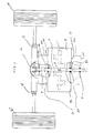
- FIG. 1 is an side view of a transverse power takeoff or output shaft in relation to a crankshaft.
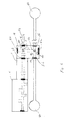
- FIG. 2 is a elevation view of a transverse power takeoff exiting both side of an engine block.
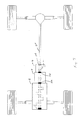
- FIG. 3 is a elevation view of a transverse power takeoff exiting one side of an engine block driving a set of front wheels.
- FIG. 4 is a top view of a transverse power take off exiting one side of an engine block driving a set of rear wheels.
- FIG. 5 is an elevation view of a transverse power take off exiting the side of an engine block that is set to one side of the vehicle.
- FIG. 6 is a side view of an engine, transmission, gearbox in which the power is delivered to a point midway between the front and rear differential.
- FIG. 7 is elevation view of an engine, transmission, gearbox in which the power is delivered to a point midway between the front and rear differential.
- FIG. 1 illustrates power shaft 1 with a powering means PM here represented by a plurality of pistons P intended to operate within internal combustion chambers.
- a powering means PM here represented by a plurality of pistons P intended to operate within internal combustion chambers.
- the shaft gearing means 2 a At substantially the center of power shafts, is the shaft gearing means 2 a, in this embodiment a worm gear.
- the transverse relationship between the powershaft 1 and the transverse shaft 3 is seen in the cross-section of transverse shaft 3 .
- Transverse shaft 3 contains a gear, in this embodiment transverse shaft worm gear 4 is illustrated.
- Transverse shaft worm gear 4 intermeshes with powershaft worm gear 2 thus transmitting power between powershaft 1 and transverse shaft 3 .
- powershaft 1 is also illustrated, this time within a transversely mounted engine block 9 .
- Transverse shaft 3 is illustrated at right angles to the long axis of powershaft 1 .
- Transverse shaft worm gear 4 of transverse shaft 3 is further illustrated.
- the transverse shaft 3 is supported by first bearing 5 and second bearing 5 A at the points the transverse shaft 3 exists the engine block first wall 9 a and engine block second wall 9 b.
- This embodiment illustrates the first power take off end 8 a of transverse shaft 3 entering first transmission 10 a forward of the engine.
- Transverse shaft 3 is further supported by transmission wall bearing 7 in the wall of first transmission 10 a opposite first bearing 5 . The shaft is then acted on by the first transmission 10 a, and the first power take offend 8 a of transverse shaft 3 enters differential 12 .
- the drive train is then split bifurcated exiting differential 12 and entering U-joints U and U′ then on to the wheels W and wheels W′.
- the second power take off end 8 b of transverse shaft 3 also exits the engine rearward supported by second bearing 5 A and is also acted on by second transmission 10 b and continues, to a rear differential where the power is then transmitted to the wheels in a fashion similar to that seen forward of the transmission.
- transverse shaft 3 enters only first transmission 10 a and the power train is then bifurcated with the power train then preceding to first laterally differential 17 a and second lateral differential 17 b and then on to the wheels W and W′.
- FIG. 4 illustrates an alternative embodiment of a power train orientation in which the transverse shaft 3 exits the rear of a front mounted engine, is acted upon by only second transmission 10 b and then enters a rear differential 13 .
- This configuration will find application in rear wheel drive vehicles.
- FIG. 5 illustrates the embodiment of an engine mounted to one side of the longitudinal centerline of a vehicle. The transverse shaft 3 then exits the engine supported by first bearing 5 and second bearing 5 a. The shaft is acted upon by side mounted transmission 10 e which altars the power train direction, in this case 90 degrees, exiting below the transmission 10 e through bearing 5 c.
- FIG. 6 illustrates a longitudinally oriented engine block E and transmission T with the transverse shaft 3 being contained within gearbox 19 .
- transverse shaft 3 is supported within gear box 19 by first gear box bearing 5 b and second gear box bearing 5 c.
- shaft gearing means 2 a transfers power from the power shaft 7 to transverse shaft 3 through intermeshing transverse shaft worm gear 4 and power shaft worm gear 2 .
- a second gearing means 2 b is utilized to alter the power train 90 degrees using a second transverse shaft worm gear 4 a entermeshing with a cross shaft worm gear 4 b mounted on a cross shaft 20 .
- the cross shaft then transmitts power to front differential 21 and rear differential 22 .
Landscapes
- Engineering & Computer Science (AREA)
- Chemical & Material Sciences (AREA)
- Combustion & Propulsion (AREA)
- Mechanical Engineering (AREA)
- General Engineering & Computer Science (AREA)
- Transportation (AREA)
- Arrangement And Driving Of Transmission Devices (AREA)
Abstract
A power transmission shaft wherein power is transmitted to a transverse shaft by a shaft gearing means with the transverse shaft having a first power take off end and a second power take off end with a plurality of bearing supporting the shafts within either a conventional longitudinal internal combustion engine or a transversely mounted engine.
Description
- Not applicable.
- Not applicable.
- Not applicable.
- This invention relates to a power transmission system and more particularly to a system whereby an engine output shaft aligned transversely to a crankshaft is driven by an appropriate gearing mechanism. This allows power takeoffs to be located both in front and behind a transversely mounted engine or to each side of a longitudinally mounted engine. With a conventional longitudinally mounted engine, the engine, crankshaft, transmission and differentials are mounted in-line with the axis of the automobile. In conventional transverse engine configurations, the power is transmitted at one end of the crankshaft. The power drive train is then required to double back through a transmission, then into a differential whereupon the power is transmitted to the wheels. Power transmission from the transmission to dual differentials is seen in some present automobile configurations. Such engine/drive train configurations do not lend themselves to multiple engine outputs. In either existing configuration, power transmitted from one end of the crankshaft results in significant torsional loading and concomitant wear on engine components. Furthermore, the directional rotational momentum of the crankshaft and other internal engine components results in the engine pitching toward the direction of rotation.
- It is, therefore, a principal object of this invention to provide an improved system for power transmission for the internal combustion engine or any engine, for example, generating rotational force on a shaft. It is a further object of this invention to provide power takeoffs through a shaft terminating both in front and behind the engine. It is a further object of this invention to transmit the power from the crankshaft to the transverse shaft at substantially the midpoint of the crankshaft thereby improving engine balance and reducing torsional engine pitch. It is a further object of this invention to reduce the torsional loading on the crankshaft and thereby reducing wear on engine components. It is a further object of this invention to reduce the gearage necessary to allow the doubling back of the engine drive train as seen in conventional transversely mounted engines. It is a further object of this invention to allow space saving engine/drive train configurations that will find application in many types of vehicles other than automobiles.
- The present invention is directed to an apparatus adapted to be embodied in an internal combustion engine comprised of a plurality of combustion chambers or by any engine whereby power is generated and transmitted to a rotating engine output shaft or crankshaft. The crankshaft is supported by a pair of bearings located at the end of each crankshaft. The midpoint of the crankshaft is occupied by a gear, which can take the form of several configurations. The object of this gear would be to transmit the engine power to a geared shaft mounted in a transverse arrangement relative to the crankshaft. The shaft would exit the engine block. The points of exit would also be supported by bearings. This would result a first and second engine output. Either the first, second or both engine outputs could then, if applicable, enter a transmission and a differential thereby driving an axle.
- The advantage of this system is that engines and drive trains may adopt a variety of positions and orientations allowing incorporation into a significant number of vehicle types. Further, the ability to adopt a variety of orientations could conserve space within vehicle types. These drive train configurations could be incorporated into automobiles, buses, boats, tanks and other armored vehicles or any type of vehicle that would benefit from the ability to flexibly orient a drive train.
- FIG. 1 is an side view of a transverse power takeoff or output shaft in relation to a crankshaft.
- FIG. 2 is a elevation view of a transverse power takeoff exiting both side of an engine block.
- FIG. 3 is a elevation view of a transverse power takeoff exiting one side of an engine block driving a set of front wheels.
- FIG. 4 is a top view of a transverse power take off exiting one side of an engine block driving a set of rear wheels.
- FIG. 5 is an elevation view of a transverse power take off exiting the side of an engine block that is set to one side of the vehicle.
- FIG. 6 is a side view of an engine, transmission, gearbox in which the power is delivered to a point midway between the front and rear differential.
- FIG. 7 is elevation view of an engine, transmission, gearbox in which the power is delivered to a point midway between the front and rear differential.
- Referring first to FIG. 1, which illustrates
power shaft 1 with a powering means PM here represented by a plurality of pistons P intended to operate within internal combustion chambers. At substantially the center of power shafts, is the shaft gearing means 2 a, in this embodiment a worm gear. The transverse relationship between thepowershaft 1 and thetransverse shaft 3 is seen in the cross-section oftransverse shaft 3.Transverse shaft 3 contains a gear, in this embodiment transverseshaft worm gear 4 is illustrated. Transverseshaft worm gear 4 intermeshes withpowershaft worm gear 2 thus transmitting power betweenpowershaft 1 andtransverse shaft 3. Turning now to FIG. 2,powershaft 1 is also illustrated, this time within a transversely mountedengine block 9.Transverse shaft 3 is illustrated at right angles to the long axis ofpowershaft 1. Transverseshaft worm gear 4 oftransverse shaft 3 is further illustrated. Thetransverse shaft 3 is supported by first bearing 5 and second bearing 5A at the points thetransverse shaft 3 exists the engine block first wall 9 a and engine block second wall 9 b. This embodiment illustrates the first power take off end 8 a oftransverse shaft 3 entering first transmission 10 a forward of the engine.Transverse shaft 3 is further supported by transmission wall bearing 7 in the wall of first transmission 10 a opposite first bearing 5. The shaft is then acted on by the first transmission 10 a, and the first power take offend 8 a oftransverse shaft 3 entersdifferential 12. The drive train is then split bifurcated exitingdifferential 12 and entering U-joints U and U′ then on to the wheels W and wheels W′. In this embodiment the second power take off end 8 b oftransverse shaft 3 also exits the engine rearward supported by second bearing 5A and is also acted on by second transmission 10 b and continues, to a rear differential where the power is then transmitted to the wheels in a fashion similar to that seen forward of the transmission. - An alternate embodiment is illustrated in FIG. 3 where it is seen that
transverse shaft 3 enters only first transmission 10 a and the power train is then bifurcated with the power train then preceding to first laterally differential 17 a and second lateral differential 17 b and then on to the wheels W and W′. - FIG. 4 illustrates an alternative embodiment of a power train orientation in which the
transverse shaft 3 exits the rear of a front mounted engine, is acted upon by only second transmission 10 b and then enters arear differential 13. This configuration will find application in rear wheel drive vehicles. FIG. 5 illustrates the embodiment of an engine mounted to one side of the longitudinal centerline of a vehicle. Thetransverse shaft 3 then exits the engine supported by first bearing 5 and second bearing 5 a. The shaft is acted upon by side mounted transmission 10 e which altars the power train direction, in this case 90 degrees, exiting below the transmission 10 e through bearing 5 c. The power train then exits the side mounted transmission 10 e, enterslower differential 18, then is bifurcated whereupon it enters U-joint U and U′ and to wheels W and W′. FIG. 6 illustrates a longitudinally oriented engine block E and transmission T with thetransverse shaft 3 being contained withingearbox 19. Heretransverse shaft 3 is supported withingear box 19 by first gear box bearing 5 b and second gear box bearing 5 c. As shaft gearing means 2 a transfers power from thepower shaft 7 totransverse shaft 3 through intermeshing transverseshaft worm gear 4 and powershaft worm gear 2. Here a second gearing means 2 b is utilized to alter the power train 90 degrees using a second transverseshaft worm gear 4 a entermeshing with a cross shaft worm gear 4 b mounted on across shaft 20. The cross shaft then transmitts power to front differential 21 and rear differential 22.
Claims (1)
1. A power transmission system comprising:
a power shaft,
a shaft gearing means mounted to said power shaft,
a transverse shaft having a first power take off end and a second power take off end, said transverse shaft rotatably communicating with said shaft gearing means, whereby power is transmitted from said power shaft to said transverse shaft,
a plurality of bearings supporting said power shaft and said transverse shaft,
a transversely mounted engine block in which said power shaft and said transverse shaft are rotatably mounted,
a first transmission, said first transmission receiving said a first power take off end,
a first differential, said first differential receiving said first power take off end from said first transmission, whereby power is then transmitted laterally thorough universal joints an on to a set of front wheels.
Priority Applications (1)
| Application Number | Priority Date | Filing Date | Title |
|---|---|---|---|
| US10/126,763 US20030196845A1 (en) | 2002-04-19 | 2002-04-19 | Transverse power transmission system |
Applications Claiming Priority (1)
| Application Number | Priority Date | Filing Date | Title |
|---|---|---|---|
| US10/126,763 US20030196845A1 (en) | 2002-04-19 | 2002-04-19 | Transverse power transmission system |
Publications (1)
| Publication Number | Publication Date |
|---|---|
| US20030196845A1 true US20030196845A1 (en) | 2003-10-23 |
Family
ID=29215099
Family Applications (1)
| Application Number | Title | Priority Date | Filing Date |
|---|---|---|---|
| US10/126,763 Abandoned US20030196845A1 (en) | 2002-04-19 | 2002-04-19 | Transverse power transmission system |
Country Status (1)
| Country | Link |
|---|---|
| US (1) | US20030196845A1 (en) |
Cited By (1)
| Publication number | Priority date | Publication date | Assignee | Title |
|---|---|---|---|---|
| US20240309819A1 (en) * | 2023-03-14 | 2024-09-19 | Kawasaki Motors, Ltd. | Power unit |
Citations (1)
| Publication number | Priority date | Publication date | Assignee | Title |
|---|---|---|---|---|
| US4548042A (en) * | 1982-07-19 | 1985-10-22 | Brothers Luther C | Propulsion system |
-
2002
- 2002-04-19 US US10/126,763 patent/US20030196845A1/en not_active Abandoned
Patent Citations (1)
| Publication number | Priority date | Publication date | Assignee | Title |
|---|---|---|---|---|
| US4548042A (en) * | 1982-07-19 | 1985-10-22 | Brothers Luther C | Propulsion system |
Cited By (1)
| Publication number | Priority date | Publication date | Assignee | Title |
|---|---|---|---|---|
| US20240309819A1 (en) * | 2023-03-14 | 2024-09-19 | Kawasaki Motors, Ltd. | Power unit |
Similar Documents
| Publication | Publication Date | Title |
|---|---|---|
| US20070158119A1 (en) | Independent axle motors for a road coupled hybrid vehicle | |
| US6821166B2 (en) | Power train | |
| US20050023885A1 (en) | Axle assembly with transverse mounted electric motors | |
| US6076623A (en) | Four-wheel drive vehicle power train | |
| JP3832465B2 (en) | Hybrid vehicle drive system | |
| RU2271940C2 (en) | Transmission and amphibian vehicle | |
| US7770483B2 (en) | Power train for an amphibious vehicle | |
| AU2001282320A1 (en) | Power train | |
| US9353847B2 (en) | Torque vectoring device | |
| US2782864A (en) | Propelling unit for motor vehicles with independent suspension driving wheels | |
| US5913938A (en) | Gear reduction assembly | |
| US5704443A (en) | Drive unit for motor vehicles | |
| US6578657B2 (en) | Driveline angle reducer | |
| US5704868A (en) | Variable angle front output shaft transfer case | |
| US7658391B1 (en) | Enclosed axle drive | |
| US20030196845A1 (en) | Transverse power transmission system | |
| GB2452062A (en) | A Hybrid Electric Motor Vehicle | |
| EP0186123A2 (en) | Vehicle drive system | |
| US6557439B2 (en) | Driving force distributing structure for four wheel drive vehicle | |
| US5669460A (en) | Automotive torque transfer case with reduced angle forward output shaft | |
| US20070049452A1 (en) | Common center section for independent rear suspension and fixed axle applications | |
| US7017702B2 (en) | Transport engine and drive arrangement | |
| JP2020101221A (en) | Drive unit for vehicle | |
| US6547028B1 (en) | Axle mounting arrangement | |
| US4530415A (en) | Power transmission device for front-engine front-drive car |
Legal Events
| Date | Code | Title | Description |
|---|---|---|---|
| STCB | Information on status: application discontinuation |
Free format text: ABANDONED -- FAILURE TO RESPOND TO AN OFFICE ACTION |