US20030196794A1 - Slip spring with heel notch - Google Patents
Slip spring with heel notch Download PDFInfo
- Publication number
- US20030196794A1 US20030196794A1 US10/418,120 US41812003A US2003196794A1 US 20030196794 A1 US20030196794 A1 US 20030196794A1 US 41812003 A US41812003 A US 41812003A US 2003196794 A1 US2003196794 A1 US 2003196794A1
- Authority
- US
- United States
- Prior art keywords
- spring
- slip
- spring retaining
- elongate body
- Prior art date
- Legal status (The legal status is an assumption and is not a legal conclusion. Google has not performed a legal analysis and makes no representation as to the accuracy of the status listed.)
- Granted
Links
- 230000013011 mating Effects 0.000 claims 1
- 238000005192 partition Methods 0.000 abstract description 12
- 238000003466 welding Methods 0.000 abstract description 4
- 238000004519 manufacturing process Methods 0.000 abstract description 3
- 230000002028 premature Effects 0.000 abstract description 2
- 238000000926 separation method Methods 0.000 abstract description 2
- 238000003754 machining Methods 0.000 description 3
- 230000009286 beneficial effect Effects 0.000 description 1
- 230000015572 biosynthetic process Effects 0.000 description 1
- 238000010276 construction Methods 0.000 description 1
- 230000007613 environmental effect Effects 0.000 description 1
- 238000009434 installation Methods 0.000 description 1
- 230000003993 interaction Effects 0.000 description 1
- 238000000034 method Methods 0.000 description 1
- 230000004048 modification Effects 0.000 description 1
- 238000012986 modification Methods 0.000 description 1
Images


Classifications
-
- E—FIXED CONSTRUCTIONS
- E21—EARTH OR ROCK DRILLING; MINING
- E21B—EARTH OR ROCK DRILLING; OBTAINING OIL, GAS, WATER, SOLUBLE OR MELTABLE MATERIALS OR A SLURRY OF MINERALS FROM WELLS
- E21B33/00—Sealing or packing boreholes or wells
- E21B33/10—Sealing or packing boreholes or wells in the borehole
- E21B33/12—Packers; Plugs
- E21B33/129—Packers; Plugs with mechanical slips for hooking into the casing
Definitions
- the present invention relates to a new arrangement for a slip spring for downhole tools such as packer tools, retrievable bridge plugs or the like.
- casing 210 has a number of partitions 212 machined or welded into the casing. Slots 214 provide a registration point for the slips 216 and allow the base of the slips to rotate free of the casing wall. The upper portion protrudes from above the casing and are held within the outer diameter of the casing wall by a retaining spring 218 (FIG. 2A) which urges the slip inwardly from the casing wall.
- the partition 212 is necessary to hold the spring 218 inside the pocket 220 provided along the length of the slip 216 since the pocket 220 has no sides to retain the spring. It is also usually necessary to weld or machine lugs along the inner portion of the partitions to further locate and center the springs securely within the slip.
- the current invention provides a self-centering spring engageable with a slip modified according to the present invention.
- a groove located at a lower center of the slip below the pocket of the slip cooperates with the spring to retain the spring against the slip and centered within the pocket without requiring the partitions or further welding of lugs to retain the springs.
- Still another object of the invention is to provide a method of centering a slip spring on a slip by providing a slip spring with a center tab which mates with a groove provided adjacent the pocket of a slip to center the slip spring on the slip independent of interaction of the slip spring with the casing.
- FIG. 1 is an environmental perspective of a prior art slip installed in a packer tool casing.
- FIG. 2A is a front plan view of a prior art slip and slip spring.
- FIG. 2B is a front plan view of a prior art slip.
- FIG. 3 is a front plan view of a slip according to the present invention having a tab receiving groove.
- FIG. 4 shows a slip spring having a centering tab according to the present invention.
- FIG. 5 shows a spring installed in the pocket of a slip according to the present invention.
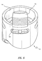
- FIG. 6 shows a slip and slip spring installed in a lugless casing of a packer tool.
- the present invention relates to an improvement in the construction and location of slips and springs inside a casing.
- FIGS. 1 and 2 show prior art casings for retaining a slip and slip spring.
- the casing 210 has a number of partitions 212 locate around its periphery. A like number of openings 214 are provided between adjacent partitions for receiving a lower end of a slip 216 .
- the slips 216 are shown in FIGS. 2A and B have a pocket 220 for receiving a prior art spring (“tabless spring”) 218 .
- tabless spring prior art spring
- the free ends of the spring 218 which are not bounded by the slip 216 are bounded by the walls of the partitions 212 . If the walls are insufficient to bound the springs, then extension lugs can be welded to an interior wall of the partition to center the spring about the slip. Disengagement of the springs will prevent the slips from withdrawing fully from the walls of the well bore during removal or repositioning of the packer tool (not shown) complicating removal of the packer tool from the well bore.
- the ends of the springs necessarily point towards the gap where the outer edge of the partition 212 meets the edge of the pocket 220 on the slip 216 . Therefore it is possible for the spring to “escape” by sliding between the side wall of the partition and the back of the pocket 220 if the spring is allowed to rotate. Further welding (or machining) of lugs to prevent this escape are often required to further trap the spring into place.
- the present invention teaches a modification of the slip and spring.
- the slip spring 18 has been modified according to the present invention to include a tab 22 centered about its length and protruding downwardly therefrom.
- the tab is shaped to mate with a groove 24 machined or otherwise formed into the slip preferably below in foot of the slip below the slip pocket 20 .
- the exact shape of the tab and groove is not essential as long as the groove is shaped to closely receive the tab.
- the sides of the tab are rounded and smoothed so that the spring can engage the groove securely without catching and to simplify formation of the tab.
- the tab should likewise be sized such that the spring cannot disengage from the groove as the spring slides vertically within the pocket.
- the tab should also be sized sufficiently to withstand any torque or other forces placed on the tab as the slips are installed or move during operation.
- the spring 18 is trapped in the pocket 20 of the slip 16 between the slip and the inner casing wall.
- the slip 16 is located in the casing by positioning the lower end of the slip in the opening 14 of the casing.
- the spring 18 is thus centered about the slip about the tab 22 riding in the groove 24 .
- the spring is prevented towards the slip or radially outwardly from the slip by the slip and the casing wall.
- the spring is prevented from moving vertically by the walls of the pocket 20 .
- the spring is prevented from moving out of the pocket along the casing wall by the tab 22 . Additionally the spring cannot rotate (i.e., one end moves closer to the slip as one end moves away from the slip) by the tab. Therefore the slip and spring act as a joined pair and the spring cannot prematurely disengage from the slip.
- tab and groove have the beneficial result of eliminating the need for the partitions significantly simplifying the machining of the casing as readily apparent from a review of the prior art casing in FIG. 1 and the casing of the current invention in FIG. 6. Welding or machining of lugs to hold the springs is also eliminated saving additional man hours and materials.
Landscapes
- Life Sciences & Earth Sciences (AREA)
- Engineering & Computer Science (AREA)
- Geology (AREA)
- Mining & Mineral Resources (AREA)
- Physics & Mathematics (AREA)
- Environmental & Geological Engineering (AREA)
- Fluid Mechanics (AREA)
- General Life Sciences & Earth Sciences (AREA)
- Geochemistry & Mineralogy (AREA)
- Component Parts Of Construction Machinery (AREA)
- Consolidation Of Soil By Introduction Of Solidifying Substances Into Soil (AREA)
Abstract
Description
- This application is related to application Ser. No. 60/373,309 filed Apr. 18, 2002, entitled Patriot Retrievable Production Packer which is hereby incorporated by reference.
- This application claims priority to Provisional Application 60/373,308 filed Apr. 18, 2002, and this provisional application is hereby incorporated by reference.
- A. Field of the Invention
- The present invention relates to a new arrangement for a slip spring for downhole tools such as packer tools, retrievable bridge plugs or the like.
- B. Description of the Prior Art
- In order to insert, set and retrieve packer tools and similar devices, complex arrangements of shear pins, springs, J tools, slips and drag blocks have been developed so that the packer tools or other devices can be reused. The drag blocks and slips must be able to selectively engage the inner wall of the well bore so that the tool can be set or unset, often by rotating the tool to either shear a pin, engage or disengage a J tool or by compressing or expanding the tool to lock or unlock. This is well known as shown for example in U.S. Pat. 5,197,547 to Morgan. The slips 62 in the Morgan patent are activated as the annular tapered surface 61 slides (“wedges”) behind the slips 62 forcing them outwardly until engage the well bore.
- Prior to the current invention, complex casings were developed to retain the springs and slips in place during installation and run in. As shown in FIGS. 1 and 2,
casing 210 has a number ofpartitions 212 machined or welded into the casing.Slots 214 provide a registration point for theslips 216 and allow the base of the slips to rotate free of the casing wall. The upper portion protrudes from above the casing and are held within the outer diameter of the casing wall by a retaining spring 218 (FIG. 2A) which urges the slip inwardly from the casing wall. Thepartition 212 is necessary to hold thespring 218 inside thepocket 220 provided along the length of theslip 216 since thepocket 220 has no sides to retain the spring. It is also usually necessary to weld or machine lugs along the inner portion of the partitions to further locate and center the springs securely within the slip. - The current invention provides a self-centering spring engageable with a slip modified according to the present invention. A groove located at a lower center of the slip below the pocket of the slip cooperates with the spring to retain the spring against the slip and centered within the pocket without requiring the partitions or further welding of lugs to retain the springs.
- None of the above inventions and patents, taken either singly or in combination, is seen to describe the instant invention as claimed.
- Accordingly, it is a principal object of the invention to provide a slip spring with a centering or retaining tab for positioning the slip spring relative to a slip.
- It is another object of the invention to provide a combination of slip and centered slip spring which can be used in a packer tool with out requiring lugs to position the slip and or slip spring.
- It is a further object of the invention to provide a cooperating slip spring tab and slip groove to center a slip spring in the pocket of a slip.
- Still another object of the invention is to provide a method of centering a slip spring on a slip by providing a slip spring with a center tab which mates with a groove provided adjacent the pocket of a slip to center the slip spring on the slip independent of interaction of the slip spring with the casing.
- It is an object of the invention to provide improved elements and arrangements thereof in an apparatus for the purposes described which is inexpensive, dependable and fully effective in accomplishing its intended purposes.
- These and other objects of the present invention will become readily apparent upon further review of the following specification and drawings.
- FIG. 1 is an environmental perspective of a prior art slip installed in a packer tool casing.
- FIG. 2A is a front plan view of a prior art slip and slip spring.
- FIG. 2B is a front plan view of a prior art slip.
- FIG. 3 is a front plan view of a slip according to the present invention having a tab receiving groove.
- FIG. 4 shows a slip spring having a centering tab according to the present invention.
- FIG. 5 shows a spring installed in the pocket of a slip according to the present invention.
- FIG. 6 shows a slip and slip spring installed in a lugless casing of a packer tool.
- Similar reference characters denote corresponding features consistently throughout the attached drawings.
- The present invention relates to an improvement in the construction and location of slips and springs inside a casing.
- FIGS. 1 and 2 show prior art casings for retaining a slip and slip spring. The
casing 210 has a number ofpartitions 212 locate around its periphery. A like number ofopenings 214 are provided between adjacent partitions for receiving a lower end of aslip 216. Theslips 216 are shown in FIGS. 2A and B have apocket 220 for receiving a prior art spring (“tabless spring”) 218. When theslip 216 withspring 218 located in its pocket is inserted into thecasing 210 the spring is trapped between the slip and casing. The top and bottom of the spring are bounded by the walls of thepocket 218 of theslip 216. The free ends of thespring 218 which are not bounded by theslip 216 are bounded by the walls of thepartitions 212. If the walls are insufficient to bound the springs, then extension lugs can be welded to an interior wall of the partition to center the spring about the slip. Disengagement of the springs will prevent the slips from withdrawing fully from the walls of the well bore during removal or repositioning of the packer tool (not shown) complicating removal of the packer tool from the well bore. - Because the springs are curved in the prior art arrangement, the ends of the springs necessarily point towards the gap where the outer edge of the
partition 212 meets the edge of thepocket 220 on theslip 216. Therefore it is possible for the spring to “escape” by sliding between the side wall of the partition and the back of thepocket 220 if the spring is allowed to rotate. Further welding (or machining) of lugs to prevent this escape are often required to further trap the spring into place. - In order to prevent premature separation of the slip and slip spring and to simplify production of the slip casing, the present invention teaches a modification of the slip and spring. As shows in FIGS. 3-5, the
slip spring 18 has been modified according to the present invention to include a tab 22 centered about its length and protruding downwardly therefrom. The tab is shaped to mate with agroove 24 machined or otherwise formed into the slip preferably below in foot of the slip below the slip pocket 20. The exact shape of the tab and groove is not essential as long as the groove is shaped to closely receive the tab. Preferably the sides of the tab are rounded and smoothed so that the spring can engage the groove securely without catching and to simplify formation of the tab. The tab should likewise be sized such that the spring cannot disengage from the groove as the spring slides vertically within the pocket. The tab should also be sized sufficiently to withstand any torque or other forces placed on the tab as the slips are installed or move during operation. - As shown in FIG. 6, when the
slip 16 andspring 18 are installed into thecasing 10, thespring 18 is trapped in the pocket 20 of theslip 16 between the slip and the inner casing wall. Theslip 16 is located in the casing by positioning the lower end of the slip in the opening 14 of the casing. Thespring 18 is thus centered about the slip about the tab 22 riding in thegroove 24. The spring is prevented towards the slip or radially outwardly from the slip by the slip and the casing wall. The spring is prevented from moving vertically by the walls of the pocket 20. The spring is prevented from moving out of the pocket along the casing wall by the tab 22. Additionally the spring cannot rotate (i.e., one end moves closer to the slip as one end moves away from the slip) by the tab. Therefore the slip and spring act as a joined pair and the spring cannot prematurely disengage from the slip. - The inclusion of the tab and groove have the beneficial result of eliminating the need for the partitions significantly simplifying the machining of the casing as readily apparent from a review of the prior art casing in FIG. 1 and the casing of the current invention in FIG. 6. Welding or machining of lugs to hold the springs is also eliminated saving additional man hours and materials.
- In operation, when the slips are urged outwardly by a wedge or other tapered surface, the springs will compress allowing the slips to move outwardly from the casing causing the slip teeth to move outwardly against a well bore or other surface surrounding the casing. When the slips. 16 are to be withdrawn into alignment with the casing and as a wedge or tapered surface is released from behind the slips, the spring urges the slip inwardly from the well bore as the spring pushes against the inner wall of the casing releasing the teeth of the slip.
- It is to be understood that the present invention is not limited to the sole embodiment described above, but encompasses any and all embodiments within the scope of the following claims.
Claims (10)
Priority Applications (3)
| Application Number | Priority Date | Filing Date | Title |
|---|---|---|---|
| US10/418,120 US7082991B2 (en) | 2002-04-18 | 2003-04-18 | Slip spring with heel notch |
| US11/098,423 US20050167097A1 (en) | 2002-04-18 | 2005-04-05 | Patriot retrievable production packer |
| US11/300,280 US7591305B2 (en) | 2002-04-18 | 2005-12-15 | Patriot retrievable production packer |
Applications Claiming Priority (3)
| Application Number | Priority Date | Filing Date | Title |
|---|---|---|---|
| US37330902P | 2002-04-18 | 2002-04-18 | |
| US37330802P | 2002-04-18 | 2002-04-18 | |
| US10/418,120 US7082991B2 (en) | 2002-04-18 | 2003-04-18 | Slip spring with heel notch |
Related Child Applications (3)
| Application Number | Title | Priority Date | Filing Date |
|---|---|---|---|
| US11/098,423 Division US20050167097A1 (en) | 2002-04-18 | 2005-04-05 | Patriot retrievable production packer |
| US11/300,280 Continuation US7591305B2 (en) | 2002-04-18 | 2005-12-15 | Patriot retrievable production packer |
| US11/300,280 Division US7591305B2 (en) | 2002-04-18 | 2005-12-15 | Patriot retrievable production packer |
Publications (2)
| Publication Number | Publication Date |
|---|---|
| US20030196794A1 true US20030196794A1 (en) | 2003-10-23 |
| US7082991B2 US7082991B2 (en) | 2006-08-01 |
Family
ID=29219701
Family Applications (2)
| Application Number | Title | Priority Date | Filing Date |
|---|---|---|---|
| US10/418,120 Expired - Fee Related US7082991B2 (en) | 2002-04-18 | 2003-04-18 | Slip spring with heel notch |
| US11/098,423 Abandoned US20050167097A1 (en) | 2002-04-18 | 2005-04-05 | Patriot retrievable production packer |
Family Applications After (1)
| Application Number | Title | Priority Date | Filing Date |
|---|---|---|---|
| US11/098,423 Abandoned US20050167097A1 (en) | 2002-04-18 | 2005-04-05 | Patriot retrievable production packer |
Country Status (1)
| Country | Link |
|---|---|
| US (2) | US7082991B2 (en) |
Cited By (3)
| Publication number | Priority date | Publication date | Assignee | Title |
|---|---|---|---|---|
| CN103899272A (en) * | 2012-12-28 | 2014-07-02 | 安东石油技术(集团)有限公司 | Suspended packer |
| CN103899258A (en) * | 2012-12-28 | 2014-07-02 | 安东石油技术(集团)有限公司 | Insert type casing slip |
| CN111379536A (en) * | 2018-12-27 | 2020-07-07 | 中国石油天然气股份有限公司 | Packer (CN) |
Families Citing this family (22)
| Publication number | Priority date | Publication date | Assignee | Title |
|---|---|---|---|---|
| US7347273B2 (en) * | 2005-10-21 | 2008-03-25 | Stellarton Technologies Inc. | Bottom hold completion system for an intermittent plunger |
| US7950468B2 (en) * | 2006-07-06 | 2011-05-31 | Horton J Dale | Wellbore plug |
| USD683435S1 (en) * | 2010-09-13 | 2013-05-28 | High Performance CT Tools, L.L.C. | Plug |
| US9845651B2 (en) | 2014-03-17 | 2017-12-19 | Forums Us, Inc. | Retrievable downhole tool system |
| US11136849B2 (en) | 2019-11-05 | 2021-10-05 | Saudi Arabian Oil Company | Dual string fluid management devices for oil and gas applications |
| US11230904B2 (en) | 2019-11-11 | 2022-01-25 | Saudi Arabian Oil Company | Setting and unsetting a production packer |
| US11156052B2 (en) | 2019-12-30 | 2021-10-26 | Saudi Arabian Oil Company | Wellbore tool assembly to open collapsed tubing |
| US11260351B2 (en) | 2020-02-14 | 2022-03-01 | Saudi Arabian Oil Company | Thin film composite hollow fiber membranes fabrication systems |
| US11253819B2 (en) | 2020-05-14 | 2022-02-22 | Saudi Arabian Oil Company | Production of thin film composite hollow fiber membranes |
| US11655685B2 (en) | 2020-08-10 | 2023-05-23 | Saudi Arabian Oil Company | Downhole welding tools and related methods |
| US11549329B2 (en) | 2020-12-22 | 2023-01-10 | Saudi Arabian Oil Company | Downhole casing-casing annulus sealant injection |
| US11828128B2 (en) | 2021-01-04 | 2023-11-28 | Saudi Arabian Oil Company | Convertible bell nipple for wellbore operations |
| US11598178B2 (en) | 2021-01-08 | 2023-03-07 | Saudi Arabian Oil Company | Wellbore mud pit safety system |
| US12054999B2 (en) | 2021-03-01 | 2024-08-06 | Saudi Arabian Oil Company | Maintaining and inspecting a wellbore |
| US11448026B1 (en) | 2021-05-03 | 2022-09-20 | Saudi Arabian Oil Company | Cable head for a wireline tool |
| US11859815B2 (en) | 2021-05-18 | 2024-01-02 | Saudi Arabian Oil Company | Flare control at well sites |
| US11905791B2 (en) | 2021-08-18 | 2024-02-20 | Saudi Arabian Oil Company | Float valve for drilling and workover operations |
| US11913298B2 (en) | 2021-10-25 | 2024-02-27 | Saudi Arabian Oil Company | Downhole milling system |
| US12116326B2 (en) | 2021-11-22 | 2024-10-15 | Saudi Arabian Oil Company | Conversion of hydrogen sulfide and carbon dioxide into hydrocarbons using non-thermal plasma and a catalyst |
| US12276190B2 (en) | 2022-02-16 | 2025-04-15 | Saudi Arabian Oil Company | Ultrasonic flow check systems for wellbores |
| US11993992B2 (en) | 2022-08-29 | 2024-05-28 | Saudi Arabian Oil Company | Modified cement retainer with milling assembly |
| US12146385B2 (en) * | 2022-10-20 | 2024-11-19 | Innovex International, Inc. | Toe valve |
Citations (15)
| Publication number | Priority date | Publication date | Assignee | Title |
|---|---|---|---|---|
| US2568005A (en) * | 1950-03-08 | 1951-09-18 | Chester M Holder | Drill pipe attachment |
| US3270819A (en) * | 1964-03-09 | 1966-09-06 | Baker Oil Tools Inc | Apparatus for mechanically setting well tools |
| US3291220A (en) * | 1964-04-17 | 1966-12-13 | Cicero C Brown | Hydraulic set liner hanger |
| US3456723A (en) * | 1967-06-30 | 1969-07-22 | Camco Inc | Hydraulically set well packer |
| US3570596A (en) * | 1969-04-17 | 1971-03-16 | Otis Eng Co | Well packer and hold down means |
| US4284137A (en) * | 1980-01-07 | 1981-08-18 | Taylor William T | Anti-kick, anti-fall running tool and instrument hanger and tubing packoff tool |
| US4345646A (en) * | 1978-02-13 | 1982-08-24 | Gearhart Industries, Inc. | Apparatus for chemical cutting |
| US4530398A (en) * | 1982-08-02 | 1985-07-23 | Arrow Oil Tools, Inc. | Retrievable well bore packer |
| US4662453A (en) * | 1986-01-29 | 1987-05-05 | Halliburton Company | Liner screen tieback packer apparatus and method |
| US4921045A (en) * | 1985-12-06 | 1990-05-01 | Baker Oil Tools, Inc. | Slip retention mechanism for subterranean well packer |
| US5423382A (en) * | 1993-11-10 | 1995-06-13 | Dresser Industries, Inc. | Apparatus for releasing perforating gun equipment from a well casing |
| US5771970A (en) * | 1995-11-08 | 1998-06-30 | Northwest Tech Group Inc. | Tubing tightener |
| US6098007A (en) * | 1996-08-10 | 2000-08-01 | Daimlerchrysler Ag | Control arrangement for longitudinal dynamics of a motor vehicle |
| US6273204B1 (en) * | 1996-10-02 | 2001-08-14 | Robert Bosch Gmbh | Method and arrangement for controlling the speed of a vehicle |
| US6285945B1 (en) * | 1999-12-22 | 2001-09-04 | Visteon Global Technologies, Inc. | Method and system for controlling vehicle deceleration in an adaptive speed control system based on vehicle speed |
Family Cites Families (12)
| Publication number | Priority date | Publication date | Assignee | Title |
|---|---|---|---|---|
| US3416608A (en) * | 1966-06-27 | 1968-12-17 | Dresser Ind | Retrievable well packer |
| US3548936A (en) * | 1968-11-15 | 1970-12-22 | Dresser Ind | Well tools and gripping members therefor |
| US3631927A (en) * | 1969-12-31 | 1972-01-04 | Schlumberger Technology Corp | Well packer |
| US3746090A (en) * | 1971-06-21 | 1973-07-17 | Dresser Ind | Latch or retrievable well packer |
| US4593765A (en) * | 1984-07-03 | 1986-06-10 | Dresser Industries, Inc. | Tubing resettable well tool |
| US4693309A (en) * | 1985-06-27 | 1987-09-15 | Halliburton Company | Wireline set/tubing retrievable bridge plug |
| US4648446A (en) * | 1985-06-27 | 1987-03-10 | Halliburton Company | Wireline set/tubing retrieve packer type bridge plug |
| US4750564A (en) * | 1987-02-27 | 1988-06-14 | Dresser Industries, Inc. | Tubing resettable well packer |
| US5273109A (en) * | 1991-01-11 | 1993-12-28 | Napoleon Arizmendi | Retrievable packer |
| US5197547A (en) * | 1992-05-18 | 1993-03-30 | Morgan Allen B | Wireline set packer tool arrangement |
| US5449040A (en) * | 1994-10-04 | 1995-09-12 | Milner; John E. | Wireline-set tubing-release packer apparatus |
| US6257339B1 (en) * | 1999-10-02 | 2001-07-10 | Weatherford/Lamb, Inc | Packer system |
-
2003
- 2003-04-18 US US10/418,120 patent/US7082991B2/en not_active Expired - Fee Related
-
2005
- 2005-04-05 US US11/098,423 patent/US20050167097A1/en not_active Abandoned
Patent Citations (17)
| Publication number | Priority date | Publication date | Assignee | Title |
|---|---|---|---|---|
| US2568005A (en) * | 1950-03-08 | 1951-09-18 | Chester M Holder | Drill pipe attachment |
| US3270819A (en) * | 1964-03-09 | 1966-09-06 | Baker Oil Tools Inc | Apparatus for mechanically setting well tools |
| US3291220A (en) * | 1964-04-17 | 1966-12-13 | Cicero C Brown | Hydraulic set liner hanger |
| US3456723A (en) * | 1967-06-30 | 1969-07-22 | Camco Inc | Hydraulically set well packer |
| US3570596A (en) * | 1969-04-17 | 1971-03-16 | Otis Eng Co | Well packer and hold down means |
| US4345646A (en) * | 1978-02-13 | 1982-08-24 | Gearhart Industries, Inc. | Apparatus for chemical cutting |
| US4284137A (en) * | 1980-01-07 | 1981-08-18 | Taylor William T | Anti-kick, anti-fall running tool and instrument hanger and tubing packoff tool |
| US4530398A (en) * | 1982-08-02 | 1985-07-23 | Arrow Oil Tools, Inc. | Retrievable well bore packer |
| US4921045A (en) * | 1985-12-06 | 1990-05-01 | Baker Oil Tools, Inc. | Slip retention mechanism for subterranean well packer |
| US4662453A (en) * | 1986-01-29 | 1987-05-05 | Halliburton Company | Liner screen tieback packer apparatus and method |
| US5423382A (en) * | 1993-11-10 | 1995-06-13 | Dresser Industries, Inc. | Apparatus for releasing perforating gun equipment from a well casing |
| US5771970A (en) * | 1995-11-08 | 1998-06-30 | Northwest Tech Group Inc. | Tubing tightener |
| US6098007A (en) * | 1996-08-10 | 2000-08-01 | Daimlerchrysler Ag | Control arrangement for longitudinal dynamics of a motor vehicle |
| US6273204B1 (en) * | 1996-10-02 | 2001-08-14 | Robert Bosch Gmbh | Method and arrangement for controlling the speed of a vehicle |
| US6285945B1 (en) * | 1999-12-22 | 2001-09-04 | Visteon Global Technologies, Inc. | Method and system for controlling vehicle deceleration in an adaptive speed control system based on vehicle speed |
| US6393352B2 (en) * | 1999-12-22 | 2002-05-21 | Visteon Global Technologies, Inc. | Method and system for controlling vehicle deceleration in an adaptive speed control system based on vehicle speed |
| US6604043B2 (en) * | 1999-12-22 | 2003-08-05 | Visteon Global Technologies, Inc. | Method and system for controlling vehicle deceleration in an adaptive speed control system based on vehicle speed |
Cited By (3)
| Publication number | Priority date | Publication date | Assignee | Title |
|---|---|---|---|---|
| CN103899272A (en) * | 2012-12-28 | 2014-07-02 | 安东石油技术(集团)有限公司 | Suspended packer |
| CN103899258A (en) * | 2012-12-28 | 2014-07-02 | 安东石油技术(集团)有限公司 | Insert type casing slip |
| CN111379536A (en) * | 2018-12-27 | 2020-07-07 | 中国石油天然气股份有限公司 | Packer (CN) |
Also Published As
| Publication number | Publication date |
|---|---|
| US7082991B2 (en) | 2006-08-01 |
| US20050167097A1 (en) | 2005-08-04 |
Similar Documents
| Publication | Publication Date | Title |
|---|---|---|
| US7082991B2 (en) | Slip spring with heel notch | |
| US5954130A (en) | Retrievable milling guide anchor apparatus and associated methods | |
| US2855052A (en) | Stop collar for a well pipe | |
| US4311196A (en) | Tangentially loaded slip assembly | |
| US4510995A (en) | Downhole locking apparatus | |
| KR960703190A (en) | SYSTEM FOR IN SITUREPLACEMENT OF CUTTING MEANS FOR A GROUND DRILL | |
| US4583591A (en) | Downhole locking apparatus | |
| WO2014149146A1 (en) | Drillable slip | |
| CN106715824B (en) | Latch ring in casing head for casing hanger | |
| JPH02176091A (en) | Supporting method of cylindrical member in another cylindrical member and its apparatus | |
| US3530934A (en) | Segmented frangible slips with guide pins | |
| US3993128A (en) | Well tool for setting and supporting liners | |
| US9476262B2 (en) | Wear bushing with hanger lockdown | |
| NO347850B1 (en) | Relatively movable slip body and wicker for enhanced release capability | |
| US4262748A (en) | Remote multiple string well completion | |
| US2766010A (en) | Casing whipstocks | |
| US4978147A (en) | Elastomeric lockdown and shearout device | |
| US2296397A (en) | Well tool | |
| CA2306736C (en) | Downhole packer system | |
| WO1995014153A1 (en) | Bottom set, non-retrievable whipstock assembly | |
| WO1999042699A2 (en) | Well lock with multiple shear planes | |
| US3497002A (en) | Guided frangible slips | |
| GB2335937A (en) | A wellhead retrieval tool | |
| US4133342A (en) | Method of replacing seals in a well ram type blow out preventer | |
| US4003430A (en) | Apparatus for the replacement of seals in a well ram type blow out preventer |
Legal Events
| Date | Code | Title | Description |
|---|---|---|---|
| FPAY | Fee payment |
Year of fee payment: 4 |
|
| AS | Assignment |
Owner name: TEAM OIL TOOLS, LP, TEXAS Free format text: ASSIGNMENT OF ASSIGNORS INTEREST;ASSIGNOR:SOMMERS, MICHAEL;REEL/FRAME:027926/0477 Effective date: 20120301 |
|
| AS | Assignment |
Owner name: TEAM OIL TOOLS, LP, TEXAS Free format text: ASSIGNMENT OF ASSIGNORS INTEREST;ASSIGNORS:BROOKEY, ROBERT L;BROOKEY, ROBERT L.;REEL/FRAME:027985/0700 Effective date: 20120307 |
|
| AS | Assignment |
Owner name: CAPITAL ONE LEVERAGE FINANCE CORP., NEW YORK Free format text: SECURITY AGREEMENT;ASSIGNOR:TEAM OIL TOOLS, L.P.;REEL/FRAME:028252/0471 Effective date: 20120522 |
|
| AS | Assignment |
Owner name: WELLS FARGO BANK, NATIONAL ASSOCIATION, TEXAS Free format text: SECURITY AGREEMENT;ASSIGNOR:TEAM OIL HOLDINGS, INC.;REEL/FRAME:031248/0684 Effective date: 20130830 |
|
| FEPP | Fee payment procedure |
Free format text: PAT HOLDER NO LONGER CLAIMS SMALL ENTITY STATUS, ENTITY STATUS SET TO UNDISCOUNTED (ORIGINAL EVENT CODE: STOL); ENTITY STATUS OF PATENT OWNER: LARGE ENTITY |
|
| FPAY | Fee payment |
Year of fee payment: 8 |
|
| AS | Assignment |
Owner name: FORUM US, INC., TEXAS Free format text: ASSIGNMENT OF ASSIGNORS INTEREST;ASSIGNOR:TEAM OIL TOOLS, LP;REEL/FRAME:039947/0979 Effective date: 20160428 |
|
| AS | Assignment |
Owner name: TEAM OIL TOOLS, L.P., TEXAS Free format text: RELEASE BY SECURED PARTY;ASSIGNOR:CAPITAL ONE BUSINESS CREDIT CORPORATION;REEL/FRAME:040268/0132 Effective date: 20130830 |
|
| AS | Assignment |
Owner name: WELLS FARGO BANK, NATIONAL ASSOCIATION, NORTH CAROLINA Free format text: SECURITY INTEREST;ASSIGNORS:FORUM ENERGY TECHNOLOGIES, INC.;FORUM CANADA ULC;REEL/FRAME:044635/0355 Effective date: 20171030 Owner name: WELLS FARGO BANK, NATIONAL ASSOCIATION, NORTH CARO Free format text: SECURITY INTEREST;ASSIGNORS:FORUM ENERGY TECHNOLOGIES, INC.;FORUM CANADA ULC;REEL/FRAME:044635/0355 Effective date: 20171030 |
|
| AS | Assignment |
Owner name: WELLS FARGO BANK, NATIONAL ASSOCIATION, NORTH CAROLINA Free format text: SECURITY INTEREST;ASSIGNORS:FORUM ENERGY TECHNOLOGIES, INC.;FORUM CANADA ULC;REEL/FRAME:044812/0161 Effective date: 20171030 Owner name: WELLS FARGO BANK, NATIONAL ASSOCIATION, NORTH CARO Free format text: SECURITY INTEREST;ASSIGNORS:FORUM ENERGY TECHNOLOGIES, INC.;FORUM CANADA ULC;REEL/FRAME:044812/0161 Effective date: 20171030 |
|
| FEPP | Fee payment procedure |
Free format text: MAINTENANCE FEE REMINDER MAILED (ORIGINAL EVENT CODE: REM.) |
|
| LAPS | Lapse for failure to pay maintenance fees |
Free format text: PATENT EXPIRED FOR FAILURE TO PAY MAINTENANCE FEES (ORIGINAL EVENT CODE: EXP.); ENTITY STATUS OF PATENT OWNER: LARGE ENTITY |
|
| STCH | Information on status: patent discontinuation |
Free format text: PATENT EXPIRED DUE TO NONPAYMENT OF MAINTENANCE FEES UNDER 37 CFR 1.362 |
|
| AS | Assignment |
Owner name: INNOVEX DOWNHOLE SOLUTIONS, INC., TEXAS Free format text: RELEASE BY SECURED PARTY;ASSIGNOR:WELLS FARGO BANK, NATIONAL ASSOCIATION;REEL/FRAME:047914/0032 Effective date: 20180907 |
|
| FP | Lapsed due to failure to pay maintenance fee |
Effective date: 20180801 |
|
| AS | Assignment |
Owner name: US BANK, NATIONAL ASSOCIATION, TEXAS Free format text: SECURITY INTEREST;ASSIGNORS:FORUM ENERGY TECHNOLOGIES, INC.;FORUM US, INC.;GLOBAL TUBING, LLC;REEL/FRAME:053399/0930 Effective date: 20200804 |
|
| AS | Assignment |
Owner name: VARIPERM ENERGY SERVICES PARTNERSHIP, CANADA Free format text: SECURITY INTEREST;ASSIGNORS:FORUM ENERGY TECHNOLOGIES, INC.;FORUM US, INC.;GLOBAL TUBING, LLC;AND OTHERS;REEL/FRAME:066565/0968 Effective date: 20240104 |
|
| AS | Assignment |
Owner name: GLAS USA LLC, AS SUCESSOR AGENT AND ASSIGNEE, NEW JERSEY Free format text: ASSIGNMENT AND ASSUMPTION OF SECOND LIEN TERM LOAN INTELLECTUAL PROPERTY SECURITY AGREEMENTS;ASSIGNOR:VARIPERM ENERGY SERVICES PARTNERSHIP, AS RESIGNING COLLATERAL AGENT AND ASSIGNOR;REEL/FRAME:069067/0317 Effective date: 20240923 |
|
| AS | Assignment |
Owner name: GLOBAL TUBING, LLC, TEXAS Free format text: RELEASE OF PATENT SECURITY AGREEMENT RECORDED AT REEL 053399/FRAME 0930;ASSIGNOR:U.S. BANK NATIONAL ASSOCIATION;REEL/FRAME:069318/0330 Effective date: 20241108 Owner name: FORUM US, INC., TEXAS Free format text: RELEASE OF PATENT SECURITY AGREEMENT RECORDED AT REEL 053399/FRAME 0930;ASSIGNOR:U.S. BANK NATIONAL ASSOCIATION;REEL/FRAME:069318/0330 Effective date: 20241108 Owner name: FORUM ENERGY TECHNOLOGIES, INC., TEXAS Free format text: RELEASE OF PATENT SECURITY AGREEMENT RECORDED AT REEL 053399/FRAME 0930;ASSIGNOR:U.S. BANK NATIONAL ASSOCIATION;REEL/FRAME:069318/0330 Effective date: 20241108 |
|
| AS | Assignment |
Owner name: VARIPERM ENERGY SERVICES INC., TEXAS Free format text: RELEASE OF SECOND LIEN SECURITY INTEREST IN PATENTS RECORDED AT REEL 066565/FRAME 0968;ASSIGNOR:GLAS USA LLC;REEL/FRAME:069338/0131 Effective date: 20241107 Owner name: GLOBAL TUBING, LLC, TEXAS Free format text: RELEASE OF SECOND LIEN SECURITY INTEREST IN PATENTS RECORDED AT REEL 066565/FRAME 0968;ASSIGNOR:GLAS USA LLC;REEL/FRAME:069338/0131 Effective date: 20241107 Owner name: FORUM US, INC., TEXAS Free format text: RELEASE OF SECOND LIEN SECURITY INTEREST IN PATENTS RECORDED AT REEL 066565/FRAME 0968;ASSIGNOR:GLAS USA LLC;REEL/FRAME:069338/0131 Effective date: 20241107 Owner name: FORUM ENERGY TECHNOLOGIES, INC., TEXAS Free format text: RELEASE OF SECOND LIEN SECURITY INTEREST IN PATENTS RECORDED AT REEL 066565/FRAME 0968;ASSIGNOR:GLAS USA LLC;REEL/FRAME:069338/0131 Effective date: 20241107 |