US20030196697A1 - Relief valve - Google Patents
Relief valve Download PDFInfo
- Publication number
- US20030196697A1 US20030196697A1 US10/441,068 US44106803A US2003196697A1 US 20030196697 A1 US20030196697 A1 US 20030196697A1 US 44106803 A US44106803 A US 44106803A US 2003196697 A1 US2003196697 A1 US 2003196697A1
- Authority
- US
- United States
- Prior art keywords
- orifice
- movable member
- relief valve
- flowrate control
- circumferential surface
- Prior art date
- Legal status (The legal status is an assumption and is not a legal conclusion. Google has not performed a legal analysis and makes no representation as to the accuracy of the status listed.)
- Granted
Links
Images


Classifications
-
- F—MECHANICAL ENGINEERING; LIGHTING; HEATING; WEAPONS; BLASTING
- F16—ENGINEERING ELEMENTS AND UNITS; GENERAL MEASURES FOR PRODUCING AND MAINTAINING EFFECTIVE FUNCTIONING OF MACHINES OR INSTALLATIONS; THERMAL INSULATION IN GENERAL
- F16K—VALVES; TAPS; COCKS; ACTUATING-FLOATS; DEVICES FOR VENTING OR AERATING
- F16K17/00—Safety valves; Equalising valves, e.g. pressure relief valves
- F16K17/02—Safety valves; Equalising valves, e.g. pressure relief valves opening on surplus pressure on one side; closing on insufficient pressure on one side
- F16K17/04—Safety valves; Equalising valves, e.g. pressure relief valves opening on surplus pressure on one side; closing on insufficient pressure on one side spring-loaded
-
- F—MECHANICAL ENGINEERING; LIGHTING; HEATING; WEAPONS; BLASTING
- F04—POSITIVE - DISPLACEMENT MACHINES FOR LIQUIDS; PUMPS FOR LIQUIDS OR ELASTIC FLUIDS
- F04C—ROTARY-PISTON, OR OSCILLATING-PISTON, POSITIVE-DISPLACEMENT MACHINES FOR LIQUIDS; ROTARY-PISTON, OR OSCILLATING-PISTON, POSITIVE-DISPLACEMENT PUMPS
- F04C14/00—Control of, monitoring of, or safety arrangements for, machines, pumps or pumping installations
- F04C14/24—Control of, monitoring of, or safety arrangements for, machines, pumps or pumping installations characterised by using valves controlling pressure or flow rate, e.g. discharge valves or unloading valves
- F04C14/26—Control of, monitoring of, or safety arrangements for, machines, pumps or pumping installations characterised by using valves controlling pressure or flow rate, e.g. discharge valves or unloading valves using bypass channels
-
- F—MECHANICAL ENGINEERING; LIGHTING; HEATING; WEAPONS; BLASTING
- F16—ENGINEERING ELEMENTS AND UNITS; GENERAL MEASURES FOR PRODUCING AND MAINTAINING EFFECTIVE FUNCTIONING OF MACHINES OR INSTALLATIONS; THERMAL INSULATION IN GENERAL
- F16K—VALVES; TAPS; COCKS; ACTUATING-FLOATS; DEVICES FOR VENTING OR AERATING
- F16K15/00—Check valves
- F16K15/02—Check valves with guided rigid valve members
- F16K15/04—Check valves with guided rigid valve members shaped as balls
- F16K15/044—Check valves with guided rigid valve members shaped as balls spring-loaded
-
- F—MECHANICAL ENGINEERING; LIGHTING; HEATING; WEAPONS; BLASTING
- F16—ENGINEERING ELEMENTS AND UNITS; GENERAL MEASURES FOR PRODUCING AND MAINTAINING EFFECTIVE FUNCTIONING OF MACHINES OR INSTALLATIONS; THERMAL INSULATION IN GENERAL
- F16K—VALVES; TAPS; COCKS; ACTUATING-FLOATS; DEVICES FOR VENTING OR AERATING
- F16K17/00—Safety valves; Equalising valves, e.g. pressure relief valves
- F16K17/02—Safety valves; Equalising valves, e.g. pressure relief valves opening on surplus pressure on one side; closing on insufficient pressure on one side
- F16K17/04—Safety valves; Equalising valves, e.g. pressure relief valves opening on surplus pressure on one side; closing on insufficient pressure on one side spring-loaded
- F16K17/0406—Safety valves; Equalising valves, e.g. pressure relief valves opening on surplus pressure on one side; closing on insufficient pressure on one side spring-loaded in the form of balls
-
- F—MECHANICAL ENGINEERING; LIGHTING; HEATING; WEAPONS; BLASTING
- F16—ENGINEERING ELEMENTS AND UNITS; GENERAL MEASURES FOR PRODUCING AND MAINTAINING EFFECTIVE FUNCTIONING OF MACHINES OR INSTALLATIONS; THERMAL INSULATION IN GENERAL
- F16K—VALVES; TAPS; COCKS; ACTUATING-FLOATS; DEVICES FOR VENTING OR AERATING
- F16K17/00—Safety valves; Equalising valves, e.g. pressure relief valves
- F16K17/02—Safety valves; Equalising valves, e.g. pressure relief valves opening on surplus pressure on one side; closing on insufficient pressure on one side
- F16K17/04—Safety valves; Equalising valves, e.g. pressure relief valves opening on surplus pressure on one side; closing on insufficient pressure on one side spring-loaded
- F16K17/0433—Safety valves; Equalising valves, e.g. pressure relief valves opening on surplus pressure on one side; closing on insufficient pressure on one side spring-loaded with vibration preventing means
-
- F—MECHANICAL ENGINEERING; LIGHTING; HEATING; WEAPONS; BLASTING
- F04—POSITIVE - DISPLACEMENT MACHINES FOR LIQUIDS; PUMPS FOR LIQUIDS OR ELASTIC FLUIDS
- F04C—ROTARY-PISTON, OR OSCILLATING-PISTON, POSITIVE-DISPLACEMENT MACHINES FOR LIQUIDS; ROTARY-PISTON, OR OSCILLATING-PISTON, POSITIVE-DISPLACEMENT PUMPS
- F04C2/00—Rotary-piston machines or pumps
- F04C2/30—Rotary-piston machines or pumps having the characteristics covered by two or more groups F04C2/02, F04C2/08, F04C2/22, F04C2/24 or having the characteristics covered by one of these groups together with some other type of movement between co-operating members
- F04C2/34—Rotary-piston machines or pumps having the characteristics covered by two or more groups F04C2/02, F04C2/08, F04C2/22, F04C2/24 or having the characteristics covered by one of these groups together with some other type of movement between co-operating members having the movement defined in groups F04C2/08 or F04C2/22 and relative reciprocation between the co-operating members
- F04C2/344—Rotary-piston machines or pumps having the characteristics covered by two or more groups F04C2/02, F04C2/08, F04C2/22, F04C2/24 or having the characteristics covered by one of these groups together with some other type of movement between co-operating members having the movement defined in groups F04C2/08 or F04C2/22 and relative reciprocation between the co-operating members with vanes reciprocating with respect to the inner member
- F04C2/3446—Rotary-piston machines or pumps having the characteristics covered by two or more groups F04C2/02, F04C2/08, F04C2/22, F04C2/24 or having the characteristics covered by one of these groups together with some other type of movement between co-operating members having the movement defined in groups F04C2/08 or F04C2/22 and relative reciprocation between the co-operating members with vanes reciprocating with respect to the inner member the inner and outer member being in contact along more than one line or surface
-
- Y—GENERAL TAGGING OF NEW TECHNOLOGICAL DEVELOPMENTS; GENERAL TAGGING OF CROSS-SECTIONAL TECHNOLOGIES SPANNING OVER SEVERAL SECTIONS OF THE IPC; TECHNICAL SUBJECTS COVERED BY FORMER USPC CROSS-REFERENCE ART COLLECTIONS [XRACs] AND DIGESTS
- Y10—TECHNICAL SUBJECTS COVERED BY FORMER USPC
- Y10T—TECHNICAL SUBJECTS COVERED BY FORMER US CLASSIFICATION
- Y10T137/00—Fluid handling
- Y10T137/2496—Self-proportioning or correlating systems
- Y10T137/2559—Self-controlled branched flow systems
- Y10T137/2574—Bypass or relief controlled by main line fluid condition
- Y10T137/2579—Flow rate responsive
- Y10T137/2582—Including controlling main line flow
-
- Y—GENERAL TAGGING OF NEW TECHNOLOGICAL DEVELOPMENTS; GENERAL TAGGING OF CROSS-SECTIONAL TECHNOLOGIES SPANNING OVER SEVERAL SECTIONS OF THE IPC; TECHNICAL SUBJECTS COVERED BY FORMER USPC CROSS-REFERENCE ART COLLECTIONS [XRACs] AND DIGESTS
- Y10—TECHNICAL SUBJECTS COVERED BY FORMER USPC
- Y10T—TECHNICAL SUBJECTS COVERED BY FORMER US CLASSIFICATION
- Y10T137/00—Fluid handling
- Y10T137/2496—Self-proportioning or correlating systems
- Y10T137/2559—Self-controlled branched flow systems
- Y10T137/2574—Bypass or relief controlled by main line fluid condition
- Y10T137/2579—Flow rate responsive
- Y10T137/2589—Pilot valve operated
-
- Y—GENERAL TAGGING OF NEW TECHNOLOGICAL DEVELOPMENTS; GENERAL TAGGING OF CROSS-SECTIONAL TECHNOLOGIES SPANNING OVER SEVERAL SECTIONS OF THE IPC; TECHNICAL SUBJECTS COVERED BY FORMER USPC CROSS-REFERENCE ART COLLECTIONS [XRACs] AND DIGESTS
- Y10—TECHNICAL SUBJECTS COVERED BY FORMER USPC
- Y10T—TECHNICAL SUBJECTS COVERED BY FORMER US CLASSIFICATION
- Y10T137/00—Fluid handling
- Y10T137/7722—Line condition change responsive valves
- Y10T137/7837—Direct response valves [i.e., check valve type]
- Y10T137/785—With retarder or dashpot
- Y10T137/7852—End of valve moves inside dashpot chamber
-
- Y—GENERAL TAGGING OF NEW TECHNOLOGICAL DEVELOPMENTS; GENERAL TAGGING OF CROSS-SECTIONAL TECHNOLOGIES SPANNING OVER SEVERAL SECTIONS OF THE IPC; TECHNICAL SUBJECTS COVERED BY FORMER USPC CROSS-REFERENCE ART COLLECTIONS [XRACs] AND DIGESTS
- Y10—TECHNICAL SUBJECTS COVERED BY FORMER USPC
- Y10T—TECHNICAL SUBJECTS COVERED BY FORMER US CLASSIFICATION
- Y10T137/00—Fluid handling
- Y10T137/7722—Line condition change responsive valves
- Y10T137/7837—Direct response valves [i.e., check valve type]
- Y10T137/7904—Reciprocating valves
- Y10T137/7922—Spring biased
- Y10T137/7927—Ball valves
- Y10T137/7928—With follower
Definitions
- This invention relates to a relief valve.
- JP-A-H8-42513 published in 1996 by the Japanese Patent Office discloses a relief valve included in the flow control valve of a power steering device.
- FIG. 10 shows this flow control valve 200 .
- a relief valve 250 is incorporated in a spool 201 of the flow control valve 200 , as shown in the diagram.
- Oil supplied to a supply chamber 202 at the tip of the spool 201 from the pump port P is supplied to the power steering device via an orifice 203 and an oil supply port 204 .
- the oil pressure on the side of the oil supply port 204 (oil pressure downstream of the orifice 203 ) is introduced to a flowrate control spring chamber 205 at the base end of the spool 201 .
- the spool 201 displaces under a balance between a thrust force due to the oil pressure of the supply chamber 202 and the supply port 204 (oil pressure both upstream and downstream of the orifice 203 ), and a reaction due to the spring force of a spring 206 provided in the flow rate control spring chamber 205 and the oil pressure of the flowrate control spring chamber 205 .
- this relief valve 250 in a transient state when the movable members are pushed open, noise is produced by chattering which makes the operation of the movable members unstable. If the diameter of a seat orifice 255 is reduced, this chattering can be suppressed, but in this case pressure losses increase, and override characteristics of the relief valve 250 (characteristics of the difference between a set pressure and a cracking pressure) are impaired.
- this invention provides a relief valve, comprising a valve seat comprising a seat hole, a ball which opens and closes the seat hole from the downstream side, a movable member which supports the ball from the downstream side, a housing part which houses the movable member, and an orifice formed downstream of the seat hole which damps the vibration of the movable member and suppresses chattering by restricting an oil flow.
- this invention provides a flowrate control valve which controls the flowrate supplied from a pump to a load circuit comprising a relief valve, the relief valve comprising a valve seat having a seat hole, a ball which opens and closes the seat hole from the downstream side, a movable member which supports the ball from the downstream side, a housing part which houses the movable member, and an orifice formed downstream of the seat hole which damps the vibration of the movable member 4 and suppresses chattering by restricting an oil flow.
- the relief valve opens when the pressure on the load circuit side rises, and part of the fluid from the pump is discharged to a tank port.
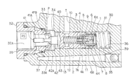
- FIG. 1 is a cross-sectional diagram of a vane pump in which the relief valve of this invention is applied.
- FIG. 2 is a cross-sectional view through a line A-A in FIG. 1.
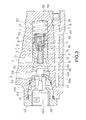
- FIG. 3 is a cross-sectional view of a flowrate control valve and relief valve.
- FIG. 4 is similar to FIG. 3, but showing a second embodiment of this invention.
- FIG. 5A is a cross-sectional view of a relief valve according to a third embodiment of this invention.
- FIG. 5B is a cross-sectional view through a line B-B in FIG. 5A.
- FIG. 6A is a cross-sectional view of a relief valve according to a fourth embodiment of this invention.
- FIG. 6B is a cross-sectional view through a line C-C in FIG. 6A.
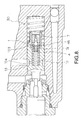
- FIG. 7 is similar to FIG. 3, but showing a fifth embodiment of this invention.
- FIG. 8 is similar to FIG. 3, but showing a sixth embodiment of this invention.
- FIG. 9 is similar to FIG. 3, but showing a seventh embodiment of this invention.
- FIG. 10 shows the prior art.
- the relief valve of this invention is incorporated in a flowrate control valve which controls the oil flowrate to a power steering device from a vane pump.
- FIG. 1, FIG. 2 show the construction of a vane pump 20 .
- the construction of the vane pump is common to each embodiment.
- the vane pump 20 comprises a body 21 , cover 22 , shaft 23 , rotor 24 , cam ring 25 and side plate 26 .
- the shaft 23 is a drive shaft of the rotor 24 installed in the body 21 , and is supported free to rotate in the body 21 .
- the shaft 23 is connected to the engine of a vehicle, not shown, and rotates together with the rotation of the engine.
- the rotor 24 is disposed on the inside of the cam ring 25 which has an elliptical inner wall. The rotor 24 is gripped between the cover 22 and the side plate 26 .
- Plural vanes 27 are arranged radially on the outer circumference of the rotor 25 .
- the vanes 27 can move into or out of the rotor 24 .
- the vanes 27 protrude until their ends come in contact with the inner circumferential surface of the cam ring 25 . Due to this, a pump chamber is formed between each of the vanes 27 , this chamber expanding and contracting together with the rotation of the rotor 24 .
- FIG. 3 shows the construction of the flowrate control valve 30 according to the first embodiment of this invention, and a relief valve 1 built into the flowrate control valve 30 .
- the flowrate control valve 30 comprises a spool 40 housed free to slide in a slide hole 31 formed in the body 21 of the vane pump 20 .
- a connector 32 is screwed into the open end of the slide hole 31 .
- the hollow part of the connector 32 is an oil supply port 32 A for supplying oil to the power steering device, not shown.
- a plug 33 is fitted to the base of the connector 32 .
- a hole is formed in the plug 33 .
- a shaft member 41 of the spool 40 passes through this hole, and a gap between the outer circumference of the shaft member 41 and the inner circumference of the hole forms an orifice 33 A.
- the opening area of the orifice 33 A can be varied by the shaft member 41 of the spool 40 in this way, but the member which vanes the opening area of this orifice 33 A may be separated from the flowrate control valve 30 , and the member which varies the opening area of the orifice 33 A may be driven by a solenoid. In this way, the opening area of the orifice 33 A can be controlled more precisely.
- the oil supply port 32 A (downstream of the orifice 33 A) communicates with a flowrate control spring chamber 35 via a communicating passage 37 .
- An orifice 38 is provided between the communicating passage 37 and the oil supply port 32 A, and an orifice 39 is provided between the communicating passage 37 and flowrate control spring chamber 35 .
- a contact step part 42 is formed at the base end of the shaft member 41 of the spool 40 .
- the diameter of the contact step part 42 is larger than the diameter of the opening of the plug 33 .
- a sliding part (land part) 43 is formed at the base end of the contact step part 42 of the spool 40 .
- the sliding part 43 slides along the inner circumferential surface of the slide hole 31 .
- the inside of the slide hole 31 is divided into a supply chamber 34 (upstream of the orifice 33 A) at the tip end of the spool 40 (left-hand side of the figure), and the flowrate control spring chamber 35 at the base end of the spool 40 (the right-hand side of the figure), by this sliding part 43 .
- the base end from the sliding part 43 of the spool 40 is a base end part 44 of smaller diameter than the sliding part 43 .
- a flowrate control spring 36 is disposed on the outer circumference of this base end part 44 .
- the base end of the flowrate control spring 36 comes in contact with the base of the slide hole 31 , and the flowrate control spring 36 pushes the spool 40 in the direction of the tip end (left-hand side of the figure).
- a pressure port P which communicates with the high-pressure passage 29 of the vane pump 20 and a tank port T which communicates with a tank, open onto the side face of the slide hole 31 .
- the pump port P is situated near the open end of the slide hole 31 , and communicates with the supply chamber 34 .
- the tank port T is situated on the far inside (right-hand side of the figure) of the slide hole from the pump port P, and communication and non-communication with the supply chamber 34 , and the communicating area when they do communicate, may be changed over by the displacement of the spool 40 .
- the relief valve 1 is built into the spool 40 from the side of the flowrate control spring chamber 35 .
- the relief valve 1 is used as a pilot valve when pressure control is performed in the flowrate control valve 30 .
- the flowrate control valve 30 also functions as a pressure control valve which decreases the supply pressure from the vane pump 20 .
- the relief valve 1 is a valve which is built into the spool 40 of the flowrate control valve 30 functions as a valve which controls the flowrate control valve 30 when the pressure of the oil supply port 32 A increases.
- the relief valve 1 comprises a return spring 3 , ball support member 4 , ball 5 , valve seat 6 and sleeve member 7 built into the valve hole 2 which opens onto the base end of the spool 40 .
- the sleeve member 7 is fixed to the inner circumferential surface at the open end of the valve hole 2 .
- the valve seat 6 is fixed to an inner circumferential surface 7 A of the sleeve member 7 .
- a seat orifice 6 A is formed coaxially with the valve seat 6 , and a downstream end part of this seat orifice 6 A forms a seat hole 6 B.
- a filter 8 is attached to the open end (upstream of the seat orifice 6 A) of the valve hole 2 .
- the ball 5 and ball support member 4 are disposed downstream of the valve seat 6 (left-hand side of FIG. 3).
- a return spring 3 is provided on the outer circumference of the ball support member 4 .
- the return spring 3 disposed between a flange 4 A of the ball support member 4 and the base surface of the valve hole 2 , pushes the ball support member 4 in the direction of the valve seat 6 .
- the ball 5 is supported by the ball support member 4 , and is pushed against the seat hole 6 B of the valve seat 6 by the spring force of the return spring 3 so as to seal the seat hole 6 B.
- a fluid pressure in the flowrate control spring chamber 35 of the flowrate control valve 30 exceeds the spring pressure of the return spring 3 , the ball 5 is pushed open, and oil is introduced into the valve hole 2 from the seat orifice 6 A and seat hole 6 B.
- the flange 4 A is formed at the base end of the ball support member 4 .
- the flange 4 A divides the inside of the valve hole 2 into a chamber 9 and a pressure control spring chamber 10 .
- a gap 11 is formed as an orifice between the flange 4 A and the inner circumferential surface 7 A of the sleeve member 7 which extends to the side of the flange 4 A.
- the gap 11 is a gap which is sufficiently narrow to have a sufficient damping effect on the movement of the ball support member 4 , and its width in the radial direction is preferably set to below ⁇ fraction (1/20) ⁇ of the inner diameter of the sleeve member 7 .
- the pressure control spring chamber 10 communicates with the tank port T via plural oil passages 12 and an outer circumferential groove 13 .
- the outer circumferential groove 13 is an annular groove formed on the outer circumference of a slide part 43 of the spool 40 .
- the vane pump 20 rotates according to the engine rotation, and oil is supplied to the supply chamber 34 of the flowrate control valve 30 from the pump port P. This oil flows into the oil supply port 32 A via the orifice 33 A, and is supplied to the power steering device.
- the oil supply amount supplied to the power steering device is small at low pump rotation speeds, the oil supply amount increases in direct proportion to the pump rotation speed.
- the differential pressure between the supply chamber 34 (upstream of the orifice 33 A) and the oil supply port 32 A (downstream of the orifice 33 A) is determined by the opening area of the orifice 33 A and the flowrate passing through the orifice 33 A, and it increases as the rotation speed of the vane pump 20 rises and the flowrate flowing through the orifice 33 A increases.
- Oil is led to the pressure control spring chamber 35 of the flowrate control valve 30 via the orifice 38 , oil passage 37 and orifice 39 .
- the spool 40 displaces in the base end direction (right-hand side of the figure) against the flowrate control spring 36 .
- the supply chamber 34 communicates with the tank port T. Hence, part of the oil supplied from the pump port P is discharged to the tank port T, and increase of the oil supply amount supplied to the power steering device is suppressed even if the pump rotation speed rises. Further, when the large diameter part 41 A of the spool 40 moves inside the orifice 33 A, the opening area of the orifice 33 A becomes narrow, and the oil supply amount supplied to the power steering device is further suppressed. In this way, the oil supply amount to the power steering device is controlled according to the pump rotation speed.
- the pressure of the supply chamber 34 is controlled as follows. For example, when the pressure of the oil supply port 32 A increases sharply due to a kickback or the like from the power steering device, this pressure is transmitted to the flowrate control spring chamber 35 via the orifice 38 , oil passage 37 and orifice 39 . Hence, the pressure of the flowrate control spring chamber 35 increases, and when it exceeds the set pressure of the relief valve 1 , the relief valve 1 is pushed open, and the flowrate control spring chamber 35 and tank port T are made to communicate.
- the ball 5 and ball support member 4 are pushed open against the spring force of the return spring 3 , and oil in the flowrate control spring chamber 35 is discharged to the tank port T via the filter 8 , the seat orifice 6 A, the seat hole 6 B, a chamber 9 , the gap 11 which functions as an orifice, a pressure control spring chamber 10 , an oil passage 12 and the outer circumferential groove 13 .
- the pressure of the flowrate control spring chamber 35 decreases, and the spool 40 retreats toward the right of the figure.
- the supply pressure of the supply chamber 34 is discharged to the tank port T, and is controlled so that it does not become excessive.
- the opening area of the orifice 33 A is made narrower by the large diameter part 41 A, and the flowrate flowing into the power steering device is limited.
- the relief valve 1 functions in this way in pressure control, but according to this embodiment, the gap 11 is formed between the flange 4 A and the inner circumferential surface 7 A of the sleeve member 7 . Therefore, due to the resistance (pressure loss) and damping force when oil passes through this gap 11 , override is improved, the operation of the ball support member 4 is stabilized, and chattering is suppressed. Specifically, vibration of the ball support member 4 in the side and axial directions is suppressed, and noise accompanying this vibration is prevented.
- FIG. 4 shows a second embodiment
- the second embodiment is different from the first embodiment in the following points.
- the sleeve member 7 of the second embodiment is shorter than that of the first embodiment, and it does not extend to the side of the flange 4 A of the ball support member 4 . Instead, a guide depression 62 A is formed in a valve hole 2 on the side of the flange 4 A, and a gap 63 between the flange 4 A and guide depression 62 A functions as an orifice.
- the gap 63 is sufficiently narrow to have a sufficient damping effect on the movement (vibration) of the ball support member 4 , and the width in the radial direction is preferably set to less than ⁇ fraction (1/20) ⁇ of the inner diameter of the depression 62 A.
- the gap 63 may be formed between the flange 4 A and the inner circumferential surface of the valve hole 2 which does not have a depression.
- FIG. 5A shows the relief valve 1 according to a third embodiment.
- FIG. 5B shows a cross-sectional view through a line B-B in FIG. 5A.
- the third embodiment is different from the first embodiment in the following points. Also in the third embodiment, the relief valve 1 is built into the spool 40 of the flowrate control valve 30 as in the case of the aforesaid first embodiment.
- the flange 4 A of the ball support member 4 is made wider in the axial direction, and its outer circumferential surfaces slides on the inner circumferential surface 7 A of the sleeve member 7 .
- Plural grooves 73 (in this embodiment, four notches provided at 90 degree intervals) are formed extending in the axial direction of the ball support member 4 , and these grooves 73 function as orifices.
- the grooves 73 are set to a width and depth at which sufficient damping effect can be exerted on the movement (vibration) of the ball support member 4 .
- the grooves 73 are formed by cutting notches out of the outer circumferential surface of the flange 4 A, so they are easily formed, precise machining is easy, and precision of the damping force setting is enhanced. Further, as the grooves 73 are formed on the outer circumferential surface of the flange 4 A, they are not sealed off by the edges of the return spring 3 . In this embodiment, the grooves 73 are formed in the outer circumference of the flange 4 A, but they may be formed in the inner circumference 7 A of the sleeve member 7 .
- FIG. 6A shows a fourth embodiment.
- FIG. 6B shows a vertical cross-sectional through a line C-C of FIG. 6A.
- the fourth embodiment differs from the first embodiment in the following points. Also in the fourth embodiment, the relief valve 1 is built into the spool 40 of the flowrate control valve 30 .
- the flange 4 A of the ball support member 4 is made wider in the axial direction, and its outer circumferential surfaces slides completely on the inner circumferential surface 7 A of the sleeve member 7 .
- Plural depressions 83 which open onto the pressure control spring chamber 10 are formed in the outer circumferential surface of the flange 4 A.
- holes 84 which axially pass through the flange 4 A are provided in the inner part of the depressions 83 .
- These throughholes 84 function as orifices.
- the cross-sectional areas of the throughholes 84 are set to a size such that a sufficient damping effect on the movement (vibration) of the ball support member 4 is obtained.
- the throughholes 84 Due to the throughholes 84 , an identical effect is obtained in the fourth embodiment as in the first embodiment. Further, the flange 4 A comes in contact with the inner circumferential surface 7 A of the sleeve member 7 , so vibration of the ball support member 4 in the side direction is completely prevented.
- the orifice is formed as the throughholes 84 which pass through the flange 4 A, so it can be easily formed, precise machining is easy, and the precision of the damping force setting is enhanced. Further, the throughholes 84 are formed inside the depression parts 83 , so even if the return spring 3 is installed at the end of the flange 4 , they are not sealed off by the end of the return spring 3 .
- FIG. 7 shows a fifth embodiment.
- the fifth embodiment differs from the first embodiment in the following points. The remaining features of the construction are identical.
- the pressure control spring chamber 10 and outer circumferential groove 13 communicate not through the oil passage 12 but through an orifice 93 .
- FIG. 8 shows a sixth embodiment.
- a notch-shaped orifice 103 is formed on the outer circumference of the flange 4 A.
- the flange 4 A of the ball support member 4 slides on the inner circumferential surface 7 A of the sleeve member 7 , and the notch-shaped orifice 103 is formed on the outer circumference of the flange 4 A.
- the cross-sectional area of the orifice 103 is set to a size such that a sufficient damping effect is given to the movement (vibration) of the ball support member 4 .
- the pressure control valve chamber 10 and outer circumferential groove 13 communicate via an orifice 104 . Due to this construction, vibration of the ball support member 4 in the side direction is more definitely prevented.
- FIG. 9 shows a seventh embodiment.
- the construction of the relief valve 1 is identical to that of the first embodiment, however the opening area of an orifice 118 between the pump port P and an oil supply port 120 which supplies oil to the power steering device is made variable by a solenoid valve 110 , unlike the first embodiment.
- the spool 40 of the flowrate control valve 20 comprises an end part 46 of small diameter situated at the end of the sliding part 43 which slides in the slide hole 31 .
- the pump port P opens onto the side of this end part 46 .
- the tank port T opens onto the side of the slide part 43 , and opens onto the end part 46 when the spool 14 has retracted so that part of the fluid from the pump port P is discharged to the tank port T.
- the solenoid valve 110 is disposed between the oil supply port 120 which communicates with the power steering device, and the pump port P.
- the solenoid valve 110 comprises a fixed iron core 112 which has a coil 111 on the outer circumference, and a rod 114 which has a movable iron core on the outer circumference.
- the rod 114 is supported free to slide in an axial direction via bearings 115 , 116 , and is driven by energizing the coil 111 .
- the end part of the rod 114 engages with the opening of a seat 117 .
- the outer circumferential part of this rod 114 and the seat 117 form an orifice 118 , the opening area of the orifice 118 being varied by the retraction of the rod 114 .
- the orifice downstream of the seat hole of the relief valve may be provided in another way.
- the relief valve was applied to a flowrate control valve of a vane pump supplying oil pressure to the power steering device, but the invention is not limited to this arrangement, and may be applied to a relief valve used for any application.
Landscapes
- Engineering & Computer Science (AREA)
- General Engineering & Computer Science (AREA)
- Mechanical Engineering (AREA)
- Physics & Mathematics (AREA)
- Fluid Mechanics (AREA)
- Safety Valves (AREA)
- Power Steering Mechanism (AREA)
Abstract
A gap 11 between a flange 4A of a ball support member 4 and the inner circumferential surface of a sleeve member 7 functions as an orifice for restricting an oil flow downstream of a seat hole (6B). The movement of the ball support member 4 is stabilized, pressure is generated in a chamber 9 downstream of a seat hole 6B, and the override characteristics of the relief valve 1 are improved.
Description
- This invention relates to a relief valve.
- JP-A-H8-42513 published in 1996 by the Japanese Patent Office discloses a relief valve included in the flow control valve of a power steering device.
- FIG. 10 shows this
flow control valve 200. Arelief valve 250 is incorporated in aspool 201 of theflow control valve 200, as shown in the diagram. - Oil supplied to a
supply chamber 202 at the tip of thespool 201 from the pump port P is supplied to the power steering device via anorifice 203 and anoil supply port 204. - The oil pressure on the side of the oil supply port 204 (oil pressure downstream of the orifice 203) is introduced to a flowrate
control spring chamber 205 at the base end of thespool 201. Thespool 201 displaces under a balance between a thrust force due to the oil pressure of thesupply chamber 202 and the supply port 204 (oil pressure both upstream and downstream of the orifice 203), and a reaction due to the spring force of aspring 206 provided in the flow ratecontrol spring chamber 205 and the oil pressure of the flowratecontrol spring chamber 205. When the differential pressure upstream and downstream of theorifice 203 increases due to an increase of the pump rotation speed, the thrust force due to the oil pressure of thesupply chamber 202 exceeds the reaction force, thespool 201 displaces in the base direction (left-hand direction of FIG. 10), and thesupply chamber 202 communicates with a tank port T. Therefore, part of the flowrate from the pump port P is returned to the tank, and the flowrate is controlled. - When the load on the power steering device increases and the oil pressure of the
oil supply port 204 sharply increases, if the oil pressure of the pressurecontrol spring chamber 205 exceeds the set pressure of therelief valve 250, therelief valve 250 is pushed open, and oil in the pressurecontrol spring chamber 205 escapes to the tank port T. As a result, thespool 201 displaces in the base end direction, oil pressure in thesupply chamber 202 escapes to the tank port T. and the supply pressure is prevented from increasing beyond the permitted pressure. - However, in the
aforesaid relief valve 250, there is a large gap between aball support member 252 which supports aball 251, and the inner circumference of avalve hole 253, so movable members (theball 251 and ball support member 252) easily vibrate in a side direction (radial direction) due to the effect of the inclination of areturn spring 254 and the side force of the flow when therelief valve 250 opens. - Further, in this
relief valve 250, in a transient state when the movable members are pushed open, noise is produced by chattering which makes the operation of the movable members unstable. If the diameter of aseat orifice 255 is reduced, this chattering can be suppressed, but in this case pressure losses increase, and override characteristics of the relief valve 250 (characteristics of the difference between a set pressure and a cracking pressure) are impaired. - It is therefore an object of this invention to stabilize the operation of movable members, prevent chattering and improve override characteristics in a relief valve.
- In order to achieve the above object, this invention provides a relief valve, comprising a valve seat comprising a seat hole, a ball which opens and closes the seat hole from the downstream side, a movable member which supports the ball from the downstream side, a housing part which houses the movable member, and an orifice formed downstream of the seat hole which damps the vibration of the movable member and suppresses chattering by restricting an oil flow.
- According to an aspect of this invention, this invention provides a flowrate control valve which controls the flowrate supplied from a pump to a load circuit comprising a relief valve, the relief valve comprising a valve seat having a seat hole, a ball which opens and closes the seat hole from the downstream side, a movable member which supports the ball from the downstream side, a housing part which houses the movable member, and an orifice formed downstream of the seat hole which damps the vibration of the
movable member 4 and suppresses chattering by restricting an oil flow. The relief valve opens when the pressure on the load circuit side rises, and part of the fluid from the pump is discharged to a tank port. - The details as well as other features and advantages of this invention are set forth in the remainder of the specification and are shown in the accompanying drawings.
- FIG. 1 is a cross-sectional diagram of a vane pump in which the relief valve of this invention is applied.
- FIG. 2 is a cross-sectional view through a line A-A in FIG. 1.
- FIG. 3 is a cross-sectional view of a flowrate control valve and relief valve.
- FIG. 4 is similar to FIG. 3, but showing a second embodiment of this invention.
- FIG. 5A is a cross-sectional view of a relief valve according to a third embodiment of this invention. FIG. 5B is a cross-sectional view through a line B-B in FIG. 5A.
- FIG. 6A is a cross-sectional view of a relief valve according to a fourth embodiment of this invention. FIG. 6B is a cross-sectional view through a line C-C in FIG. 6A.
- FIG. 7 is similar to FIG. 3, but showing a fifth embodiment of this invention.
- FIG. 8 is similar to FIG. 3, but showing a sixth embodiment of this invention.
- FIG. 9 is similar to FIG. 3, but showing a seventh embodiment of this invention.
- FIG. 10 shows the prior art.
- In the following embodiments, the relief valve of this invention is incorporated in a flowrate control valve which controls the oil flowrate to a power steering device from a vane pump.
- FIG. 1, FIG. 2 show the construction of a
vane pump 20. The construction of the vane pump is common to each embodiment. - The
vane pump 20 comprises abody 21,cover 22,shaft 23,rotor 24,cam ring 25 andside plate 26. - The
shaft 23 is a drive shaft of therotor 24 installed in thebody 21, and is supported free to rotate in thebody 21. Theshaft 23 is connected to the engine of a vehicle, not shown, and rotates together with the rotation of the engine. - The
rotor 24 is disposed on the inside of thecam ring 25 which has an elliptical inner wall. Therotor 24 is gripped between thecover 22 and theside plate 26. -
Plural vanes 27 are arranged radially on the outer circumference of therotor 25. Thevanes 27 can move into or out of therotor 24. When therotor 24 rotates, thevanes 27 protrude until their ends come in contact with the inner circumferential surface of thecam ring 25. Due to this, a pump chamber is formed between each of thevanes 27, this chamber expanding and contracting together with the rotation of therotor 24. - In the expansion stroke, these pump chambers draw in oil from a
low pressure passage 28 which communicates with a tank, not shown. On the other hand, in the contraction stroke, oil is discharged into a high-pressure passage 29. The high-pressure passage 29 communicates with the power steering device, not shown, via aflowrate control valve 30 described later. - FIG. 3 shows the construction of the
flowrate control valve 30 according to the first embodiment of this invention, and arelief valve 1 built into theflowrate control valve 30. - When the engine rotates at low speed, oil supplied to the power steering device must increase together with increase of the engine rotation speed. On the other hand, when the engine rotates at high speed, the amount of oil supplied to the power steering device must be limited so that it does not increase even if the engine rotation speed rises. The
flowrate control valve 30 is provided for this flowrate control, and when the engine rotation speed (rotation speed of the vane pump 20) increases, it drains the oil which exceeds the required oil supply amount. - The
flowrate control valve 30 comprises aspool 40 housed free to slide in aslide hole 31 formed in thebody 21 of thevane pump 20. Aconnector 32 is screwed into the open end of theslide hole 31. The hollow part of theconnector 32 is anoil supply port 32A for supplying oil to the power steering device, not shown. - A
plug 33 is fitted to the base of theconnector 32. A hole is formed in theplug 33. Ashaft member 41 of thespool 40 passes through this hole, and a gap between the outer circumference of theshaft member 41 and the inner circumference of the hole forms anorifice 33A. - A
large diameter part 41A and asmall diameter part 41B having a smaller diameter than thelarge diameter part 41A, are formed in order from the end at theshaft member 41 of thespool 40. Consequently, the opening area of theorifice 33A varies according to whether thelarge diameter part 41A or thesmall diameter part 41B is inside the hole. - In this embodiment, the opening area of the
orifice 33A can be varied by theshaft member 41 of thespool 40 in this way, but the member which vanes the opening area of thisorifice 33A may be separated from theflowrate control valve 30, and the member which varies the opening area of theorifice 33A may be driven by a solenoid. In this way, the opening area of theorifice 33A can be controlled more precisely. - The
oil supply port 32A (downstream of theorifice 33A) communicates with a flowratecontrol spring chamber 35 via a communicatingpassage 37. Anorifice 38 is provided between the communicatingpassage 37 and theoil supply port 32A, and anorifice 39 is provided between the communicatingpassage 37 and flowratecontrol spring chamber 35. - A
contact step part 42 is formed at the base end of theshaft member 41 of thespool 40. The diameter of thecontact step part 42 is larger than the diameter of the opening of theplug 33. Hence, when thespool 40 displaces towards the tip end (left-hand side of the figure), and anend face 42A of thecontact step part 42 comes in contact with theplug 33, theorifice 33A is closed by thecontact step part 42. - A sliding part (land part) 43 is formed at the base end of the
contact step part 42 of thespool 40. The slidingpart 43 slides along the inner circumferential surface of theslide hole 31. The inside of theslide hole 31 is divided into a supply chamber 34 (upstream of theorifice 33A) at the tip end of the spool 40 (left-hand side of the figure), and the flowratecontrol spring chamber 35 at the base end of the spool 40 (the right-hand side of the figure), by this slidingpart 43. - The base end from the sliding
part 43 of thespool 40 is abase end part 44 of smaller diameter than the slidingpart 43. Aflowrate control spring 36 is disposed on the outer circumference of thisbase end part 44. The base end of theflowrate control spring 36 comes in contact with the base of theslide hole 31, and theflowrate control spring 36 pushes thespool 40 in the direction of the tip end (left-hand side of the figure). - A pressure port P which communicates with the high-
pressure passage 29 of thevane pump 20 and a tank port T which communicates with a tank, open onto the side face of theslide hole 31. The pump port P is situated near the open end of theslide hole 31, and communicates with thesupply chamber 34. The tank port T is situated on the far inside (right-hand side of the figure) of the slide hole from the pump port P, and communication and non-communication with thesupply chamber 34, and the communicating area when they do communicate, may be changed over by the displacement of thespool 40. - The
relief valve 1 is built into thespool 40 from the side of the flowratecontrol spring chamber 35. Therelief valve 1 is used as a pilot valve when pressure control is performed in theflowrate control valve 30. Specifically, when a large load acts on the power steering device and the pressure of theoil supply port 32A sharply increases, theflowrate control valve 30 also functions as a pressure control valve which decreases the supply pressure from thevane pump 20. In this pressure control, therelief valve 1 is a valve which is built into thespool 40 of theflowrate control valve 30 functions as a valve which controls theflowrate control valve 30 when the pressure of theoil supply port 32A increases. - The
relief valve 1 comprises areturn spring 3,ball support member 4,ball 5, valve seat 6 andsleeve member 7 built into thevalve hole 2 which opens onto the base end of thespool 40. - The
sleeve member 7 is fixed to the inner circumferential surface at the open end of thevalve hole 2. The valve seat 6 is fixed to an innercircumferential surface 7A of thesleeve member 7. Aseat orifice 6A is formed coaxially with the valve seat 6, and a downstream end part of thisseat orifice 6A forms aseat hole 6B. Afilter 8 is attached to the open end (upstream of theseat orifice 6A) of thevalve hole 2. - The
ball 5 andball support member 4 are disposed downstream of the valve seat 6 (left-hand side of FIG. 3). Areturn spring 3 is provided on the outer circumference of theball support member 4. Thereturn spring 3, disposed between aflange 4A of theball support member 4 and the base surface of thevalve hole 2, pushes theball support member 4 in the direction of the valve seat 6. - The
ball 5 is supported by theball support member 4, and is pushed against theseat hole 6B of the valve seat 6 by the spring force of thereturn spring 3 so as to seal theseat hole 6B. When a fluid pressure in the flowratecontrol spring chamber 35 of theflowrate control valve 30 exceeds the spring pressure of thereturn spring 3, theball 5 is pushed open, and oil is introduced into thevalve hole 2 from theseat orifice 6A andseat hole 6B. - The
flange 4A is formed at the base end of theball support member 4. Theflange 4A divides the inside of thevalve hole 2 into a chamber 9 and a pressurecontrol spring chamber 10. - A
gap 11 is formed as an orifice between theflange 4A and the innercircumferential surface 7A of thesleeve member 7 which extends to the side of theflange 4A. Thegap 11 is a gap which is sufficiently narrow to have a sufficient damping effect on the movement of theball support member 4, and its width in the radial direction is preferably set to below {fraction (1/20)} of the inner diameter of thesleeve member 7. - Due to this
gap 11, in therelief valve 1, the movement of theball support member 4 andball 5 can be stabilized without decreasing the override characteristics, and the noise due to chattering can be suppressed. The fact that sufficient damping effect is obtained when the width (width in the radial direction) of thegap 11 is set to less than {fraction (1/20)} of the inner diameter of thesleeve member 7, is confirmed by experiment and analysis. - The pressure
control spring chamber 10 communicates with the tank port T viaplural oil passages 12 and an outercircumferential groove 13. The outercircumferential groove 13 is an annular groove formed on the outer circumference of aslide part 43 of thespool 40. - Next, the operation of this device will be described.
- When the engine, not shown, is started, the
vane pump 20 rotates according to the engine rotation, and oil is supplied to thesupply chamber 34 of theflowrate control valve 30 from the pump port P. This oil flows into theoil supply port 32A via theorifice 33A, and is supplied to the power steering device. When the oil supply amount supplied to the power steering device is small at low pump rotation speeds, the oil supply amount increases in direct proportion to the pump rotation speed. - In this case, the differential pressure between the supply chamber 34 (upstream of the
orifice 33A) and theoil supply port 32A (downstream of theorifice 33A) is determined by the opening area of theorifice 33A and the flowrate passing through theorifice 33A, and it increases as the rotation speed of thevane pump 20 rises and the flowrate flowing through theorifice 33A increases. - Oil is led to the pressure
control spring chamber 35 of theflowrate control valve 30 via theorifice 38,oil passage 37 andorifice 39. When the rotation speed of thevane pump 20 increases and the differential pressure upstream and downstream of theorifice 33A increases, thespool 40 displaces in the base end direction (right-hand side of the figure) against theflowrate control spring 36. Specifically, when the flowrate passing through theorifice 33A increases, a thrust force (product of a pressure P1 of thesupply chamber 34 and pressure receiving area A1 on the side of thesupply chamber 34 of thespool 40 and the axial force due to the pressure in theoil supply port 32A) which presses thespool 40 in the base end direction, exceeds the reaction (sum of the spring force F of theflowrate control spring 36, and product of the pressure P2 of the flowrate and controlspring chamber 35 and pressure receiving area A2 on the side of the flowratecontrol spring chamber 35 of the spool 40) which presses thespool 40 back towards the tip end (left-hand side of the figure), thespool 40 retreats in the base end direction. - Due to the retreat of the
spool 40, thesupply chamber 34 communicates with the tank port T. Hence, part of the oil supplied from the pump port P is discharged to the tank port T, and increase of the oil supply amount supplied to the power steering device is suppressed even if the pump rotation speed rises. Further, when thelarge diameter part 41A of thespool 40 moves inside theorifice 33A, the opening area of theorifice 33A becomes narrow, and the oil supply amount supplied to the power steering device is further suppressed. In this way, the oil supply amount to the power steering device is controlled according to the pump rotation speed. - Also, the pressure of the
supply chamber 34 is controlled as follows. For example, when the pressure of theoil supply port 32A increases sharply due to a kickback or the like from the power steering device, this pressure is transmitted to the flowratecontrol spring chamber 35 via theorifice 38,oil passage 37 andorifice 39. Hence, the pressure of the flowratecontrol spring chamber 35 increases, and when it exceeds the set pressure of therelief valve 1, therelief valve 1 is pushed open, and the flowratecontrol spring chamber 35 and tank port T are made to communicate. Specifically, theball 5 andball support member 4 are pushed open against the spring force of thereturn spring 3, and oil in the flowratecontrol spring chamber 35 is discharged to the tank port T via thefilter 8, theseat orifice 6A, theseat hole 6B, a chamber 9, thegap 11 which functions as an orifice, a pressurecontrol spring chamber 10, anoil passage 12 and the outercircumferential groove 13. As a result, the pressure of the flowratecontrol spring chamber 35 decreases, and thespool 40 retreats toward the right of the figure. Hence, the supply pressure of thesupply chamber 34 is discharged to the tank port T, and is controlled so that it does not become excessive. Further, the opening area of theorifice 33A is made narrower by thelarge diameter part 41A, and the flowrate flowing into the power steering device is limited. - The
relief valve 1 functions in this way in pressure control, but according to this embodiment, thegap 11 is formed between theflange 4A and the innercircumferential surface 7A of thesleeve member 7. Therefore, due to the resistance (pressure loss) and damping force when oil passes through thisgap 11, override is improved, the operation of theball support member 4 is stabilized, and chattering is suppressed. Specifically, vibration of theball support member 4 in the side and axial directions is suppressed, and noise accompanying this vibration is prevented. - Also, due to the
gap 11, a pressure appears in the chamber 9 (downstream of theseat hole 6B of the relief valve 1) and the pressure increases as the flowrate increases, so the override characteristics of the relief valve 1 (difference between the set pressure and cracking pressure of the relief valve 1) improve. - FIG. 4 shows a second embodiment.
- The second embodiment is different from the first embodiment in the following points.
- The
sleeve member 7 of the second embodiment is shorter than that of the first embodiment, and it does not extend to the side of theflange 4A of theball support member 4. Instead, a guide depression 62A is formed in avalve hole 2 on the side of theflange 4A, and agap 63 between theflange 4A and guide depression 62A functions as an orifice. Thegap 63 is sufficiently narrow to have a sufficient damping effect on the movement (vibration) of theball support member 4, and the width in the radial direction is preferably set to less than {fraction (1/20)} of the inner diameter of the depression 62A. - Therefore, in addition to having an identical effect to that of the first embodiment, according to the second embodiment, there is no need to adjust the relation between the inner diameter of the
sleeve member 7 and the outer diameter of theflange 4A forming thegap 63, and freedom of design is enhanced. - It is not absolutely necessary to provide the guide depression 62A in the
valve hole 2, and thegap 63 may be formed between theflange 4A and the inner circumferential surface of thevalve hole 2 which does not have a depression. - FIG. 5A shows the
relief valve 1 according to a third embodiment. FIG. 5B shows a cross-sectional view through a line B-B in FIG. 5A. - The third embodiment is different from the first embodiment in the following points. Also in the third embodiment, the
relief valve 1 is built into thespool 40 of theflowrate control valve 30 as in the case of the aforesaid first embodiment. - In the third embodiment, the
flange 4A of theball support member 4 is made wider in the axial direction, and its outer circumferential surfaces slides on the innercircumferential surface 7A of thesleeve member 7. Plural grooves 73 (in this embodiment, four notches provided at 90 degree intervals) are formed extending in the axial direction of theball support member 4, and thesegrooves 73 function as orifices. Thegrooves 73 are set to a width and depth at which sufficient damping effect can be exerted on the movement (vibration) of theball support member 4. - Due to these
grooves 73, in the third embodiment, an identical effect is obtained as in the case of the first embodiment. Theflange 4A comes in contact with the innercircumferential surface 7A of thesleeve member 7, so vibration of theball support member 4 in the side direction is completely prevented. According to this embodiment, thegrooves 73 are formed by cutting notches out of the outer circumferential surface of theflange 4A, so they are easily formed, precise machining is easy, and precision of the damping force setting is enhanced. Further, as thegrooves 73 are formed on the outer circumferential surface of theflange 4A, they are not sealed off by the edges of thereturn spring 3. In this embodiment, thegrooves 73 are formed in the outer circumference of theflange 4A, but they may be formed in theinner circumference 7A of thesleeve member 7. - FIG. 6A shows a fourth embodiment. FIG. 6B shows a vertical cross-sectional through a line C-C of FIG. 6A.
- The fourth embodiment differs from the first embodiment in the following points. Also in the fourth embodiment, the
relief valve 1 is built into thespool 40 of theflowrate control valve 30. - According to the fourth embodiment, the
flange 4A of theball support member 4 is made wider in the axial direction, and its outer circumferential surfaces slides completely on the innercircumferential surface 7A of thesleeve member 7.Plural depressions 83 which open onto the pressurecontrol spring chamber 10 are formed in the outer circumferential surface of theflange 4A. Further, holes 84 which axially pass through theflange 4A are provided in the inner part of thedepressions 83. Thesethroughholes 84 function as orifices. The cross-sectional areas of thethroughholes 84 are set to a size such that a sufficient damping effect on the movement (vibration) of theball support member 4 is obtained. - Due to the
throughholes 84, an identical effect is obtained in the fourth embodiment as in the first embodiment. Further, theflange 4A comes in contact with the innercircumferential surface 7A of thesleeve member 7, so vibration of theball support member 4 in the side direction is completely prevented. The orifice is formed as thethroughholes 84 which pass through theflange 4A, so it can be easily formed, precise machining is easy, and the precision of the damping force setting is enhanced. Further, thethroughholes 84 are formed inside thedepression parts 83, so even if thereturn spring 3 is installed at the end of theflange 4, they are not sealed off by the end of thereturn spring 3. - FIG. 7 shows a fifth embodiment.
- The fifth embodiment differs from the first embodiment in the following points. The remaining features of the construction are identical.
- In the fifth embodiment, the pressure
control spring chamber 10 and outercircumferential groove 13 communicate not through theoil passage 12 but through anorifice 93. - When the
relief valve 1 is pushed open, due to the flow through theorifice 93, a suitable back pressure is set up in the pressurecontrol spring chamber 10, the effect of mixing with air is suppressed, and cavitation in the pressurecontrol spring chamber 10 is prevented. The operation of theball support member 4 is stabilized, and noise due to chattering is reduced. Further, a pressure appears in the chamber 9 downstream of theseat hole 6B, so override characteristics are improved. - FIG. 8 shows a sixth embodiment.
- In the sixth embodiment, in the construction of the fifth embodiment (FIG. 7) wherein the pressure
control valve chamber 10 and the outercircumferential groove 13 communicate via an orifice, a notch-shapedorifice 103 is formed on the outer circumference of theflange 4A. - Specifically, in the sixth embodiment, the
flange 4A of theball support member 4 slides on the innercircumferential surface 7A of thesleeve member 7, and the notch-shapedorifice 103 is formed on the outer circumference of theflange 4A. The cross-sectional area of theorifice 103 is set to a size such that a sufficient damping effect is given to the movement (vibration) of theball support member 4. - The pressure
control valve chamber 10 and outercircumferential groove 13 communicate via anorifice 104. Due to this construction, vibration of theball support member 4 in the side direction is more definitely prevented. - FIG. 9 shows a seventh embodiment.
- In the seventh embodiment, the construction of the
relief valve 1 is identical to that of the first embodiment, however the opening area of anorifice 118 between the pump port P and anoil supply port 120 which supplies oil to the power steering device is made variable by asolenoid valve 110, unlike the first embodiment. - The
spool 40 of theflowrate control valve 20 comprises anend part 46 of small diameter situated at the end of the slidingpart 43 which slides in theslide hole 31. The pump port P opens onto the side of thisend part 46. The tank port T opens onto the side of theslide part 43, and opens onto theend part 46 when the spool 14 has retracted so that part of the fluid from the pump port P is discharged to the tank port T. - The
solenoid valve 110 is disposed between theoil supply port 120 which communicates with the power steering device, and the pump port P. Thesolenoid valve 110 comprises a fixediron core 112 which has acoil 111 on the outer circumference, and arod 114 which has a movable iron core on the outer circumference. Therod 114 is supported free to slide in an axial direction viabearings coil 111. The end part of therod 114 engages with the opening of aseat 117. The outer circumferential part of thisrod 114 and theseat 117 form anorifice 118, the opening area of theorifice 118 being varied by the retraction of therod 114. - Due to this construction, control of the opening area of the
orifice 118 between the pump port P andoil supply port 120 can be performed more precisely. - The aforesaid embodiments may be combined, and any desired combination may be used if it is possible.
- The orifice downstream of the seat hole of the relief valve may be provided in another way.
- In the above embodiments, the relief valve was applied to a flowrate control valve of a vane pump supplying oil pressure to the power steering device, but the invention is not limited to this arrangement, and may be applied to a relief valve used for any application.
- The embodiments of this invention in which an exclusive property or privilege is claimed are defined as follows:
Claims (17)
1. A relief valve, comprising:
a valve seat comprising a seat hole;
a ball which opens and closes the seat hole from the downstream side;
a movable member which supports the ball from the downstream side;
a housing part which houses the movable member; and
an orifice formed downstream of the seat hole which damps the vibration of the movable member and suppresses chattering by restricting an oil flow.
2. The relief valve as defined in claim 1 , wherein the orifice is a gap between the movable member and the inner circumferential surface of the housing part.
3. The relief valve as defined in claim 2 , wherein:
the movable member further comprises a flange of circular cross-section;
the orifice is a gap between the flange and the inner circumferential surface of the housing part; and
the width of the gap in the radial direction is less than {fraction (1/20)} of the inner diameter of the housing part.
4. The relief valve as defined in claim 1 , wherein:
the movable member slides on the inner circumferential surface of the housing part; and
the orifice is grooves formed on either one of the outer circumferential surface of the movable member, and the inner circumferential surface of the housing part.
5. The relief valve as defined in claim 1 , wherein:
the movable member slides on the inner circumferential surface of the housing part; and
the orifice is a throughhole through which the movable member passes.
6. The relief valve as defined in claim 5 , wherein the relief valve comprises a return spring disposed on the movable member;
depressions are formed in the movable member on the side where the return spring is installed; and
the throughhole opens onto the depressions.
7. The relief valve as defined in claim 1 , further comprising:
a return spring disposed on the movable member;
a spring chamber housing the return spring downstream of the seat hole; and
a second orifice between the spring chamber and a tank port.
8. The relief valve as defined in claim 1 , further comprising:
a third orifice upstream of the seat hole.
9. A flowrate control valve which controls the flowrate supplied from a pump to a load circuit comprising a relief valve, the relief valve comprising:
a valve seat having a seat hole;
a ball which opens and closes the seat hole from the downstream side;
a movable member which supports the ball from the downstream side;
a housing part which houses the movable member; and
an orifice formed downstream of the seat hole which damps the vibration of the movable member 4 and suppresses chattering by restricting an oil flow, wherein:
the relief valve opens when the pressure on the load circuit side rises, and part of the fluid from the pump is discharged to a tank port.
10. The flowrate control valve as defined in claim 9 , wherein the orifice is a gap between the movable member and the inner circumferential surface of the housing part.
11. The flowrate control valve as defined in claim 10 , wherein:
the movable member further comprises a flange of circular cross-section;
the orifice is a gap between the flange and the inner circumferential surface of the housing part; and
the width of the gap in the radial direction is less than {fraction (1/20)} of the inner diameter of the housing part.
12. The flowrate control valve as defined in claim 9 , wherein:
the movable member slides on the inner circumferential surface of the housing part; and
the orifice is grooves formed on either one of the outer circumferential surface of the movable member, and the inner circumferential surface of the housing part.
13. The flowrate control valve as defined in claim 9 , wherein:
the movable member slides on the inner circumferential surface of the housing part; and
the orifice is a throughhole through which the movable member passes.
14. The flowrate control valve as defined in claim 13 , wherein the relief valve comprises a return spring disposed on the movable member;
a depression is formed in the movable member on the side where the return spring is installed; and
the throughhole opens onto the depression.
15. The flowrate control valve as defined in claim 9 , further comprising:
a return spring disposed in the movable member;
a spring chamber housing the return spring downstream of the seat hole, and a second orifice between the spring chamber and the tank port.
16. The flowrate control valve as defined in claim 9 , further comprising:
a third orifice upstream of the seat hole.
17. The flowrate control valve as defined in any of claims 9 through 16, comprising:
a spool;
a supply chamber formed on one side of the spool;
a flowrate control valve chamber formed on the other side of the spool; and
a flowrate control spring provided in the flowrate control spring chamber which pushes the spool in the direction of the supply chamber, wherein:
a pump pressure is led to the supply chamber;
oil is supplied from the supply chamber to a supply port to the load circuit via a supply orifice;
the pressure downstream of the supply orifice is led to the flowrate control valve chamber via at least one orifice or throat, when the spool retracts in the direction of the flowrate control spring chamber, the supply chamber communicates with the tank port,
the relief valve is built into the spool from the side of the flowrate control spring chamber, and
when the relief valve opens, the flowrate control spring chamber communicates with the tank port.
Priority Applications (1)
| Application Number | Priority Date | Filing Date | Title |
|---|---|---|---|
| US10/441,068 US6675823B2 (en) | 2000-09-11 | 2003-05-20 | Relief valve |
Applications Claiming Priority (5)
| Application Number | Priority Date | Filing Date | Title |
|---|---|---|---|
| JP2000275215A JP3502820B2 (en) | 2000-05-18 | 2000-09-11 | Relief valve |
| JP2000275215 | 2000-09-11 | ||
| JP2000-275215 | 2000-09-11 | ||
| US09/930,242 US20020029801A1 (en) | 2000-09-11 | 2001-08-16 | Relief valve |
| US10/441,068 US6675823B2 (en) | 2000-09-11 | 2003-05-20 | Relief valve |
Related Parent Applications (1)
| Application Number | Title | Priority Date | Filing Date |
|---|---|---|---|
| US09/930,242 Division US20020029801A1 (en) | 2000-09-11 | 2001-08-16 | Relief valve |
Publications (2)
| Publication Number | Publication Date |
|---|---|
| US20030196697A1 true US20030196697A1 (en) | 2003-10-23 |
| US6675823B2 US6675823B2 (en) | 2004-01-13 |
Family
ID=18760871
Family Applications (2)
| Application Number | Title | Priority Date | Filing Date |
|---|---|---|---|
| US09/930,242 Abandoned US20020029801A1 (en) | 2000-09-11 | 2001-08-16 | Relief valve |
| US10/441,068 Expired - Lifetime US6675823B2 (en) | 2000-09-11 | 2003-05-20 | Relief valve |
Family Applications Before (1)
| Application Number | Title | Priority Date | Filing Date |
|---|---|---|---|
| US09/930,242 Abandoned US20020029801A1 (en) | 2000-09-11 | 2001-08-16 | Relief valve |
Country Status (5)
| Country | Link |
|---|---|
| US (2) | US20020029801A1 (en) |
| KR (1) | KR20020020852A (en) |
| CN (1) | CN1258052C (en) |
| DE (1) | DE10144641B4 (en) |
| FR (1) | FR2813937B1 (en) |
Cited By (3)
| Publication number | Priority date | Publication date | Assignee | Title |
|---|---|---|---|---|
| EP1605166A1 (en) * | 2004-06-10 | 2005-12-14 | JI-EE Industry Co., Ltd. | Relief valve for a hydraulic pump |
| US20050279411A1 (en) * | 2004-06-18 | 2005-12-22 | Ji-Ee Industry Co., Ltd. | Relief valve for hydraulic pump |
| EP1734295A1 (en) * | 2005-06-15 | 2006-12-20 | OIL CONTROL S.p.A. | A valve for progressive braking |
Families Citing this family (16)
| Publication number | Priority date | Publication date | Assignee | Title |
|---|---|---|---|---|
| DE102004048861A1 (en) * | 2004-10-07 | 2006-04-20 | Robert Bosch Gmbh | Electromagnetically actuated valve, in particular for brake power systems in motor vehicles |
| US20060196476A1 (en) * | 2005-02-28 | 2006-09-07 | Caterpillar Inc. | Pressure relief valve |
| CN100344903C (en) * | 2005-08-16 | 2007-10-24 | 浙江大学 | Overflow valve of fast-centralized lubricating system |
| IT1396473B1 (en) * | 2009-03-30 | 2012-12-14 | Magneti Marelli Spa | FUEL PUMP WITH A MAXIMUM PRESSURE VALVE PERFECTED FOR A DIRECT INJECTION SYSTEM |
| US8506270B2 (en) * | 2009-12-15 | 2013-08-13 | Hitachi Automotive Systems, Ltd. | Variable displacement vane pump |
| CN102444733B (en) * | 2011-12-14 | 2015-01-07 | 四川省机械研究设计院 | Self-buffering multistage safety valve |
| US9616920B2 (en) * | 2012-09-13 | 2017-04-11 | Trw Automotive U.S. Llc | Power steering apparatus |
| US9315208B2 (en) * | 2012-09-13 | 2016-04-19 | Trw Automotive U.S. Llc | Power steering apparatus |
| JP6302735B2 (en) * | 2014-04-24 | 2018-03-28 | Kyb株式会社 | Relief valve |
| JP6082788B2 (en) * | 2015-07-31 | 2017-02-15 | Kyb株式会社 | Composite valve and bidirectional flow control valve using the same |
| DE102016202709B3 (en) * | 2016-02-22 | 2017-03-09 | Magna Powertrain Bad Homburg GmbH | Valve seat to protect the housing |
| KR102433370B1 (en) * | 2017-08-08 | 2022-08-18 | 주식회사 만도 | Check valve |
| US10662737B2 (en) * | 2018-07-24 | 2020-05-26 | Baker Hughes, A Ge Company, Llc | Fluid injection valve |
| DE102018113952B4 (en) * | 2018-07-30 | 2022-01-27 | Danfoss Power Solutions Aps | Hydraulic steering unit |
| CN110985714A (en) * | 2019-11-28 | 2020-04-10 | 北京卫星制造厂有限公司 | UHPLC liquid phase pump ultrahigh pressure high accuracy check valve |
| JP2022118606A (en) * | 2021-02-02 | 2022-08-15 | 日立Astemo株式会社 | Valve device, pump device, and trim tilt device |
Citations (4)
| Publication number | Priority date | Publication date | Assignee | Title |
|---|---|---|---|---|
| US1104201A (en) * | 1913-03-21 | 1914-07-21 | Frank Lenzi | Non-refillable bottle. |
| US3217732A (en) * | 1962-10-03 | 1965-11-16 | Garrett Corp | Bleed-off regulator |
| US5183075A (en) * | 1986-04-12 | 1993-02-02 | Stein Guenter | Check valve |
| US5595213A (en) * | 1995-01-04 | 1997-01-21 | Huron, Inc. | Quick connector with check valve |
Family Cites Families (13)
| Publication number | Priority date | Publication date | Assignee | Title |
|---|---|---|---|---|
| US3003423A (en) * | 1957-07-11 | 1961-10-10 | Thompson Ramo Wooldridge Inc | Pressure control valve |
| US4310018A (en) * | 1980-02-13 | 1982-01-12 | Parr Manufacturing Company | Check valve assembly |
| FR2553490B1 (en) * | 1983-10-18 | 1986-01-24 | Citroen Sa | PRESSURE RELIEF WITH DAMPED VALVE |
| SE465533B (en) * | 1990-02-19 | 1991-09-23 | Saab Automobile | SILENT BACK VALVE FOR PULSING FLOW |
| JPH07107286B2 (en) * | 1990-07-06 | 1995-11-15 | 株式会社イナックス | Flash valve piston mechanism |
| DE4120360A1 (en) * | 1991-06-20 | 1992-12-24 | Zahnradfabrik Friedrichshafen | FLOW CONTROL VALVE |
| JPH0643438U (en) * | 1992-11-16 | 1994-06-10 | 株式会社ユニシアジェックス | Relief valve |
| DE59504855D1 (en) * | 1994-04-08 | 1999-03-04 | Luk Fahrzeug Hydraulik | Valve arrangement |
| JPH0842513A (en) * | 1994-08-03 | 1996-02-13 | Kayaba Ind Co Ltd | Pressure control valve |
| DE19604889C2 (en) * | 1996-02-10 | 2003-01-30 | Bosch Gmbh Robert | Pressure relief valve |
| JP3636880B2 (en) * | 1997-12-19 | 2005-04-06 | ユニシア ジェーケーシー ステアリングシステム株式会社 | Pump with relief valve |
| KR20000003847U (en) * | 1998-07-29 | 2000-02-25 | 배길훈 | Flow regulating valve with relief rod of power steering steering pump |
| JP3502820B2 (en) * | 2000-05-18 | 2004-03-02 | カヤバ工業株式会社 | Relief valve |
-
2001
- 2001-08-16 US US09/930,242 patent/US20020029801A1/en not_active Abandoned
- 2001-09-10 KR KR1020010055401A patent/KR20020020852A/en not_active Ceased
- 2001-09-10 FR FR0111687A patent/FR2813937B1/en not_active Expired - Lifetime
- 2001-09-11 CN CNB011329149A patent/CN1258052C/en not_active Expired - Fee Related
- 2001-09-11 DE DE10144641.1A patent/DE10144641B4/en not_active Expired - Fee Related
-
2003
- 2003-05-20 US US10/441,068 patent/US6675823B2/en not_active Expired - Lifetime
Patent Citations (4)
| Publication number | Priority date | Publication date | Assignee | Title |
|---|---|---|---|---|
| US1104201A (en) * | 1913-03-21 | 1914-07-21 | Frank Lenzi | Non-refillable bottle. |
| US3217732A (en) * | 1962-10-03 | 1965-11-16 | Garrett Corp | Bleed-off regulator |
| US5183075A (en) * | 1986-04-12 | 1993-02-02 | Stein Guenter | Check valve |
| US5595213A (en) * | 1995-01-04 | 1997-01-21 | Huron, Inc. | Quick connector with check valve |
Cited By (3)
| Publication number | Priority date | Publication date | Assignee | Title |
|---|---|---|---|---|
| EP1605166A1 (en) * | 2004-06-10 | 2005-12-14 | JI-EE Industry Co., Ltd. | Relief valve for a hydraulic pump |
| US20050279411A1 (en) * | 2004-06-18 | 2005-12-22 | Ji-Ee Industry Co., Ltd. | Relief valve for hydraulic pump |
| EP1734295A1 (en) * | 2005-06-15 | 2006-12-20 | OIL CONTROL S.p.A. | A valve for progressive braking |
Also Published As
| Publication number | Publication date |
|---|---|
| KR20020020852A (en) | 2002-03-16 |
| US20020029801A1 (en) | 2002-03-14 |
| US6675823B2 (en) | 2004-01-13 |
| CN1258052C (en) | 2006-05-31 |
| FR2813937A1 (en) | 2002-03-15 |
| DE10144641A1 (en) | 2002-06-06 |
| FR2813937B1 (en) | 2005-04-22 |
| CN1343847A (en) | 2002-04-10 |
| DE10144641B4 (en) | 2014-04-30 |
Similar Documents
| Publication | Publication Date | Title |
|---|---|---|
| US6675823B2 (en) | Relief valve | |
| US6530752B2 (en) | Variable displacement pump | |
| JP5897943B2 (en) | Vane pump | |
| US6352085B1 (en) | Pressure relief valve | |
| EP1350957B1 (en) | Variable displacement vane pump | |
| US4768540A (en) | Flow control apparatus | |
| JP3520232B2 (en) | Flow control device | |
| JP3820273B2 (en) | Hydraulic pump flow control valve | |
| JP3746386B2 (en) | Variable displacement vane pump | |
| US6267566B1 (en) | Oil pump | |
| KR100278186B1 (en) | Flow control device for hydraulic pump | |
| JP3534691B2 (en) | Relief valve | |
| KR900005711B1 (en) | Flow control valve | |
| JP3502820B2 (en) | Relief valve | |
| JP2010127214A (en) | Vane pump | |
| JP2016211523A (en) | Pump unit | |
| KR100289785B1 (en) | Hydraulic pump for power steering system | |
| JP3758855B2 (en) | Variable displacement vane pump | |
| US5220939A (en) | Flow control apparatus | |
| JP3746388B2 (en) | Variable displacement vane pump | |
| JP2002089727A (en) | Pressure control valve | |
| JPS61250391A (en) | Hydraulic pump | |
| US8197239B2 (en) | Flow-control valve device for a pump | |
| JP4052968B2 (en) | Variable displacement vane pump and pressure supply device | |
| KR950015025B1 (en) | Flow control device |
Legal Events
| Date | Code | Title | Description |
|---|---|---|---|
| FEPP | Fee payment procedure |
Free format text: PAYOR NUMBER ASSIGNED (ORIGINAL EVENT CODE: ASPN); ENTITY STATUS OF PATENT OWNER: LARGE ENTITY |
|
| STCF | Information on status: patent grant |
Free format text: PATENTED CASE |
|
| FPAY | Fee payment |
Year of fee payment: 4 |
|
| FPAY | Fee payment |
Year of fee payment: 8 |
|
| FPAY | Fee payment |
Year of fee payment: 12 |
|
| AS | Assignment |
Owner name: KYB CORPORATION, JAPAN Free format text: CHANGE OF NAME;ASSIGNOR:KAYABA INDUSTRY CO., LTD.;REEL/FRAME:037355/0086 Effective date: 20151001 |