US20030196471A1 - Portable crimping device for crimping fitting sockets - Google Patents
Portable crimping device for crimping fitting sockets Download PDFInfo
- Publication number
- US20030196471A1 US20030196471A1 US10/177,593 US17759302A US2003196471A1 US 20030196471 A1 US20030196471 A1 US 20030196471A1 US 17759302 A US17759302 A US 17759302A US 2003196471 A1 US2003196471 A1 US 2003196471A1
- Authority
- US
- United States
- Prior art keywords
- die
- crimping
- hose
- base
- unitary frame
- Prior art date
- Legal status (The legal status is an assumption and is not a legal conclusion. Google has not performed a legal analysis and makes no representation as to the accuracy of the status listed.)
- Granted
Links
Images


Classifications
-
- B—PERFORMING OPERATIONS; TRANSPORTING
- B21—MECHANICAL METAL-WORKING WITHOUT ESSENTIALLY REMOVING MATERIAL; PUNCHING METAL
- B21D—WORKING OR PROCESSING OF SHEET METAL OR METAL TUBES, RODS OR PROFILES WITHOUT ESSENTIALLY REMOVING MATERIAL; PUNCHING METAL
- B21D39/00—Application of procedures in order to connect objects or parts, e.g. coating with sheet metal otherwise than by plating; Tube expanders
- B21D39/04—Application of procedures in order to connect objects or parts, e.g. coating with sheet metal otherwise than by plating; Tube expanders of tubes with tubes; of tubes with rods
- B21D39/048—Application of procedures in order to connect objects or parts, e.g. coating with sheet metal otherwise than by plating; Tube expanders of tubes with tubes; of tubes with rods using presses for radially crimping tubular elements
-
- B—PERFORMING OPERATIONS; TRANSPORTING
- B25—HAND TOOLS; PORTABLE POWER-DRIVEN TOOLS; MANIPULATORS
- B25B—TOOLS OR BENCH DEVICES NOT OTHERWISE PROVIDED FOR, FOR FASTENING, CONNECTING, DISENGAGING, OR HOLDING
- B25B27/00—Hand tools, specially adapted for fitting together or separating parts or objects whether or not involving some deformation, not otherwise provided for
- B25B27/02—Hand tools, specially adapted for fitting together or separating parts or objects whether or not involving some deformation, not otherwise provided for for connecting objects by press fit or detaching same
- B25B27/10—Hand tools, specially adapted for fitting together or separating parts or objects whether or not involving some deformation, not otherwise provided for for connecting objects by press fit or detaching same inserting fittings into hoses
Definitions
- This invention relates to an apparatus for crimping hose fittings onto the ends of hoses, and more particularly to a portable, preferably hand held, crimping device.
- Crimping machines or apparatuses are well known devices or mechanisms used for permanently crimping the cylindrical socket of a hose fitting onto the end of a hose.
- the cylindrical socket of the hose fitting has an inner diameter slightly larger than the outer diameter of the hose, thus allowing the hose to be inserted into the cylindrical socket.
- the end of the hose and fitting are inserted into the crimping machine that holds a crimping die segment assembly.
- the die segment assembly is radially contracted and compresses the socket onto the hose to a predetermined diameter.
- a typical crimping machine is provided with a power source, such as a hydraulic pump, that supplies pressurized hydraulic fluid to a cylinder having a movable piston disposed therein.
- a power source such as a hydraulic pump
- pressurized fluid is supplied to the cylinder, the piston moves from a first position to a second position.
- a die pusher is connected to the piston and moves with the piston. During this movement, the die pusher comes in contact with a die ring that rests on top of the radially aligned die segment assembly.
- the die segment assembly is housed within a tapered die bowl and the die segment assembly radially contracts as it moves deeper into the die bowl.
- the die segment assembly travels into the tapered die bowl, radially contracting, and crimps the fitting socket via the permanent deformation thereof. Due to forces from the transmission of hydraulic power, the longitudinal movement of the piston and die pusher, and the radial contraction of the die segment assembly, the structure of the crimping machine is subjected to various stresses. Therefore this structure must be rigid in order to withstand these stresses and produce a precise crimp diameter.
- the structure for the crimping machine is comprised of a lower base plate, an upper end plate and four column rods interconnecting both plates. Examples of a crimping machine with this structure are shown in U.S. Pat. No. 3,851,514 to Chen et al., U.S. Pat. No. 4,781,055 to Phipps, and U.S. Pat. No. 4,515,006 to Stanley. As discussed previously, forces from the power transmission and movement of the componentry can cause stresses to the structure of the crimping machine. These stresses can adversely affect the linkages between the plates and column rods, thus creating fatigue failures.
- Certain crimping machines are used in hose assembly fabrication facilities and are permanently affixed to a flat surface, such as a workbench, either in a horizontal or vertical angular orientation. These types of machines are large, heavy, and the weight is not evenly distributed. This may cause a top-heavy machine to tip over during operation unless permanently affixed.
- An example of this type of crimping machine shown in U.S. Pat. No. 4,309,892 to Currie, has such a vertical orientation. Therefore, this type of machine must be must be affixed to a support structure and is not easily transported to different locations.
- Portable crimping machines are used for those applications where crimping cannot take place in a hose assembly fabrication facility. These types of machines are typically lighter and smaller than those permanently affixed.
- Portable crimping machines are generally vertically oriented. A base, having a flat lower surface, is provided for setting the machine on a flat horizontal surface.
- Portable crimping machines typically have side walls or columns that are removably attached to the top and bottom plates. Examples of portable crimping machines with this design are shown in U.S. Pat. Nos. 5,437,177 and 6,125,681, both to Orcutt et al.
- forces from the power transmission and movement of the componentry can also cause stresses in the side walls and columns of portable crimping machines, creating fatigue failures in the linkages.
- Certain portable crimping devices provide handles for manual lifting. Examples of crimping machines with this feature include the above mentioned U.S. Pat. Nos. 5,437,177 and 6,125,681 to Orcutt et al. Due to the size and weight of these types of crimping devices, the portability thereof is quite limited.
- Portable crimping machines of the variety previously discussed have a structure that is likely to be damaged if the machine is dropped or topples over. These machines can be top heavy and unbalanced, lending themselves to tipping over. If this occurs, the linkages between the side walls and plates can break, or the structure becomes misaligned. Any misalignment will negatively affect the precision of the crimping process and the reliability of the crimping machine.
- the present invention provides a portable apparatus for crimping a hose fitting onto the end of a hose.
- This invention overcomes the obstacle of providing a crimping apparatus having a housing comprised of more than one structural element.
- a crimper housing with more than one structural element contains stress points localized at the junctions of these elements. These junctions are typically the failure points when crimper housings are damaged due to excessive stresses and strains.
- a feature of the present invention is to provide a hand held, portable crimper comprising a unitary frame having a longitudinal axis and four sides surrounding an open middle section, one of the sides being a base, located at one end of the middle open section, perpendicular to the longitudinal axis, and having a receiving opening longitudinally extending through.
- a top portion of the unitary frame also perpendicular to the longitudinal axis, is located at the opposite end of the open middle section from the base.
- a first side parallel with the longitudinal axis, is perpendicular to and interconnects the base and top portion.
- a second side, also parallel with the longitudinal axis and perpendicular to the base and top portion is located at the opposite side of the open middle section from the first side and also interconnects the base and top portion.
- the portable crimper also includes componentry, such as a cylinder, removably attached to an inner surface of the top portion, and a piston that is movable longitudinally from a first position to a second position within the cylinder.
- a pusher is removably attached to the piston, and has a hollow end portion.
- a removable annular die bowl is located within the receiving opening in the base.
- An annular die separator having a base portion located adjacent to the die bowl and a series of angular extensions protruding from the base portion, is positioned within the die bowl.
- An annular die segment assembly is removably positioned on top of the die separator and includes a plurality of die segments which are radially movable relative to the base receiving opening. The die segments have a generally flat upper portion and an angular lower portion adapted to mate with the angular extensions of the annular die separator.
- An annular die ring is disposed between the pusher and the die segment assembly.
- the unitary frame of the noted apparatus may further have mounting holes on at least one of the outer surfaces of the first and second side for attaching a power unit or for attaching a mounting plate.
- the unitary frame may also have blind mounting holes on the outer surface of the base portion for also attaching a mounting plate.
- Another feature of the present invention includes being able to orient the apparatus in any desired angular position during the crimping of the hose fitting to the hose.
- the mounting plates of the present invention also overcome the obstacle of locating an available flat surface for resting the crimping apparatus thereupon in order to support the abutting flat surface of the crimping apparatus.
- the unitary frame of the noted apparatus may also include a handle, located longitudinally outward of the top portion, for manual lifting purposes.
- the handle can be integral with the unitary frame.
- Another feature of the present invention includes having a portable crimping apparatus as previously set forth, wherein the unitary frame includes multiple support surfaces enabling the longitudinal axis to be angularly positioned either horizontally or vertically during the crimping of the hose fitting to the hose.
- the base, first side and second side of the unitary frame may further have a generally flat outer surface so that the noted apparatus can he placed on either the base, first side or second side during the crimping of the hose fitting to the hose.
- a further attribute of the present invention includes having a portable crimping apparatus as previously set forth, wherein the first and second side of the unitary frame are comprised of solid, essentially unapertured surfaces.
- Another feature of the present invention includes having the unitary frame of the crimping apparatus preferably taking the form of a light metal casing.
- the unitary frame may be formed from a non-metallic material, or it may be comprised of a casting of a light metal alloy, such as of aluminum.
- Another attribute of the present invention includes having a portable crimping apparatus, as previously set forth, wherein the pusher includes a mechanism for cutting hose.
- Another feature of the present invention includes having the size and weight selected in order to make the apparatus readily portable and capable of being hand-carried to remote locations by a human operator.
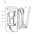
- FIG. 1 is a front, elevational view of a portable crimping device in accordance with the invention.
- FIG. 2 is a perspective view illustrating a crimper housing in accordance with the present invention.
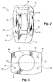
- FIG. 3 is a bottom view of the crimper housing.
- FIG. 4 is a front, cross-sectional view of the crimper housing, taken along line 4 - 4 of FIG. 3.
- FIG. 5 is an exploded view of the portable crimping device, including the crimper housing, cylinder, piston, die pusher, crimping componentry, hydraulic pump, handle, and conduit.
- FIG. 6 is a front, cross-sectional view of the symmetrical piston.
- FIG. 7 is a top, perspective view illustrating the die pusher.
- FIG. 8 is a frontal view of the symmetrical, circular die segment assembly shown in a closed position when contracted in the die bowl.
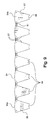
- FIG. 9 is a plan view of the die segment assembly, removed from the die bowl shown in an unrolled formation.
- FIG. 10 is a perspective view of a side mounting plate
- FIG. 11 is a perspective view of a base mounting plate used for affixing the crimper housing to a flat surface.
- FIG. 12 is a perspective view of another embodiment of a base mounting plate.
- FIG. 13 is a side view showing the die segment assembly in a contracted position, removed from the crimper housing
- FIG. 14 is a side elevational view of the hose and hose fitting of a typical hose assembly.
- FIG. 15 is a side view of the die pusher frontal opening, showing a further embodiment having a hose cutting mechanism (partially shown in dotted lines) removably attached to the die pusher.
- FIG. 1 there is illustrated a portable and preferably hand held crimping device, indicated generally at 10 , for crimping fitting sockets onto hydraulic hose ends.
- the portable (hand held) crimping device 10 includes a one-piece crimper housing 20 , a hydraulic cylinder 40 , a spring-loaded piston 45 movably situated inside the hydraulic cylinder 40 , a removable die pusher 50 , and an attachable manually operated hydraulic pump 60 .
- the portable crimping device 10 is utilized for permanently attach a fitting 95 onto the end of a hose 97 , as shown in FIG. 14 in a manner well known in the art.
- crimper housing 20 is comprised of a one-piece, generally die-cast construction, preferably made of aluminum or a similar light weight material, having four sides that surround a central opening 25 .
- crimper housing 20 can be made of a non-metallic material, preferably filled or unfilled thermoplastic and thermoset plastics, or a similar material.
- These four sides of crimper housing 20 include an apertured base portion 21 , a solid upper portion 22 , a solid first side 23 , and a solid second side 24 .
- Base portion 21 includes a cylindrical cavity 29 centrally aligned with the longitudinal axis of crimper housing 20 .
- Cavity 29 extends from an upper surface 30 to a flat, lower surface 31 of base portion 21 .
- Central aperture 27 (as shown in FIG. 4) provided in surface 30
- aperture 28 (as shown in FIG. 3) provided on base portion lower surface 31 , define the outer periphery and the longitudinal extent of cavity 29 .
- Apertures 38 are provided in base portion lower surface 31 for receiving fasteners (not shown) for affixing a base mounting plate such as 110 , 114 , and 118 (discussed below) thereto.
- Upper portion 22 Located on the opposite side of central opening 25 from base portion 21 is upper portion 22 .
- Upper portion 22 includes at least one aperture 32 (as shown in FIGS. 3 and 4) in the surface adjacent central opening 25 for receiving fasteners in order to affix a hydraulic cylinder 40 , to be discussed below.
- First side 23 and second side 24 of crimper housing 20 are both parallel to the longitudinal axis of crimper housing 20 .
- the outer surfaces of both sides 23 and 24 are generally flat and contain one or more apertures 34 , or mounting holes, for receiving fasteners (not shown) for affixing hydraulic pump 60 (as shown in FIG. 5), or for affixing a side mounting plate 110 (discussed below) thereto.
- Hydraulic pump 60 can be affixed to either of sides 23 or 24 , depending on the user's preference.
- a carrying handle 36 is provided on the opposite side of upper portion 22 from central opening 25 .
- Handle 36 extends laterally from first side 23 to second side 24 .
- Handle 36 enables the user to conveniently grasp, handle and thereby transport crimping device 10 to any location where the crimping of a hose assembly is required.
- Hydraulic cylinder 40 includes at least one aperture 41 on its upper surface that is capable of being aligned with the at least one aperture 32 in upper portion 22 of crimper housing 20 (as shown in FIG. 4). Cylinder 40 thus can be attached to crimper housing 20 via the use of a connecting fastener, not shown, into these aligned apertures.
- piston 45 has a cylindrical outer surface 46 that merges into a bottom portion 47 .
- the outer diameter of piston 45 is dimensioned for a fluid tight movable relationship with the inside diameter of cylinder 40 .
- Extending from the center of piston bottom portion 47 is a removable knob extension 48 having an outwardly directed shoulder 49 protruding from the knob periphery. If desired, knob extension 48 may be integral with piston bottom portion 47 in the manner shown in FIG. 6.
- die pusher 50 consists of a generally cylindrical hollow member having a frontal opening 51 in the forward peripheral portion thereof.
- Die pusher 50 includes a top portion 55 , with a slot 52 that extends from the frontal face to the central axis, and a flat lower edge 54 .
- a recess 53 in slot 52 is provided in order to receive shoulder 49 of piston knob extension 48 .
- Threaded aperture 56 extends through top portion 55 and is dimensioned so that a detent 58 (as shown in FIG. 5) can be received within. Detent 58 ensures that die pusher 50 does not shift when die pusher's 50 central axis is aligned with knob 48 .
- base portion 21 of crimper housing 20 has a counterbore 33 or radial recess machined in the inner surface thereof adjacent to central aperture 28 .
- Retaining ring 65 is adapted to fit within counterbore 33 .
- a spring 66 rests on top of and its lower end is held in place by retaining ring 65 .
- a die separator 67 is situated on top of spring 66 and consists of a tubular portion 68 integral with a generally flat, elongated mounting portion 69 that rests on top of spring 66 .
- Die separator 67 is preferably a one-piece structure formed of a rigid plastic material.
- the upper edge of tubular portion 68 is comprised of a series of intersecting angled surfaces 70 forming generally triangular shaped, axially extending, projections for support of a die segment assembly 80 , shown in FIG. 8, which will be discussed below.
- a die bowl 72 is located on top of an inwardly directed annular ridge 35 (FIG. 4) that protrudes into cavity 29 along the entire circumference of the inner surface of base portion 21 .
- Die bowl 72 has a cylindrical outer surface and a tapered interior surface (not shown). The taper of the interior surface is substantially equal to that of the outer surface 81 of die segment assembly 80 , as shown in FIG. 8.
- Angled surfaces 70 of die separator 67 project into the inside of die bowl 72 .
- the top surface of elongated die separator mounting portion 69 contacts a lower surface 74 of die bowl 72 .
- the top peripheral surface 73 of die bowl 72 receives a lower annular surface (not shown) of a die ring 75 .
- Die ring 75 has generally flat annular upper and lower surfaces.
- the inner diameter of die ring 75 is dimensioned such that a hose fitting with an angled end can fit therethrough.
- the height of die ring 75 varies depending on the desired crimp diameter of the fitting.
- die segment assembly 80 consists of a plurality of generally interconnected identical individual contoured die segments 84 .
- Die segment assemblies 84 are used with mating componentry (e.g. die separator 67 ) to crimp a specific style of hose fitting.
- mating componentry e.g. die separator 67
- a typical die segment assembly will change depending on the size of the fitting, but the same mating componentry could be used for all sizes of a similar style of hose fittings.
- An example of a commercially available die segment assembly is shown in U.S. Pat. No. 4,309,892 to Currie, which is assigned to the assignee of the present invention.
- Each die segment 84 generally consists of a block of cast steel in a generally pie-shaped configuration.
- Die segment 84 has a generally flat top portion 86 , a pair of flat angled sides 87 , an inner curved surface 88 generally conforming, when assembled, to the shape of the hose fitting 95 (as shown in FIG. 14) to be assembled to the hose 97 , and a vee-shaped bottom portion 89 angled generally to fit into the receiving angled surfaces 70 (as shown in FIG. 5) of die separator 67 .
- Radial outer surface 81 consists of an upper cylindrical portion 82 and a lower conical portion 83 .
- Lower conical portion 83 is tapered in a manner to match the taper of the interior surface of die bowl 72 .
- Each die segment 84 is connected to an adjacent die segment 84 by means of an intermediate rigid link 91 .
- die segment assembly 80 When die segment assembly 80 is in its closed or working position, as is best seen in FIG. 8, the two then-adjacent end die segments 84 a , 84 b are not linked together, as is best seen in FIG. 9, and thus form the first die segment 84 a and the last die segment 84 b , with intermediate die segments 84 therebetween together forming die segment assembly 80 in a manner well known in the prior art.
- hydraulic pump 60 can be attached to crimper housing 20 on the outer surface of either first side 23 or second side 24 . Apertures on two pump mounting plates 62 align with apertures 34 on first 23 or second side 24 for attachment purposes.
- Hydraulic pump 60 includes a fluid reservoir located within a cylinder 61 .
- Cylinder 61 contains a movable piston (not shown) which can be moved when an attached handle 63 is manually pivoted relative to cylinder 61 . Movement of the piston within cylinder 61 creates a pressurized fluid flow from the fluid reservoir to a conduit 90 that links hydraulic pump 60 to hydraulic cylinder 40 .
- a pressure relief knob 64 is supplied at one end of cylinder 61 in order to relieve the built-up pressure with cylinder 61 .
- mounting plates, 110 , 118 and 114 are provided for attachment to crimper housing 20 .
- side mounting plate 110 has four apertures or cutouts 111 that align with apertures 34 on one of crimper housing sides 23 or 24 (as shown in FIG. 4).
- Fasteners (not shown) are received in both sets of apertures, 111 and 34 , for affixing side mounting plate 110 to crimper housing 20 .
- Apertures 34 are also used for attaching hydraulic pump mounting plate 62 , so, for example, if hydraulic pump 60 is attached to crimper housing first side 23 , then side mounting plate 110 can be attached to crimper housing second side 24 .
- Side mounting plate 110 has an intermediate lateral extension 112 that extends outwardly from crimper housing 20 .
- a fastening mechanism such as a vise, for example, (not shown) to clamp mounting plate extension 112 during the crimping process.
- base mounting plate 118 is designed for attachment of crimper housing 20 to another, preferably flat, object, for example a horizontal table (not shown).
- Base mounting plate has a first portion 119 that can be attached to the base portion lower surface 31 and a second portion 120 that can be attached to another object.
- First portion 119 has a set of apertures 121 that align with crimper housing base portion apertures 38 (as shown in FIG. 3).
- Fasteners (not shown) are used to affix base mounting plate 118 onto base portion lower surface 31 .
- Second portion 120 has a set of apertures 122 that receive fasteners that affix second portion 120 to another object, for example a horizontal table.
- First portion 119 further has an inner edge 123 that is aligned with central aperture 28 on base portion lower surface 31 .
- base mounting plate 114 is also designed for attachment onto base portion lower surface 31 .
- Base mounting plate 114 has a set of apertures 115 that align with apertures 38 (as shown in FIG. 3). Fasteners (not shown) are used to affix base mounting plate 114 onto base portion lower surface 31 .
- An angled extension 116 extends from plate 114 at any predetermined angle.
- Base mounting plate 114 has an inner edge 117 that is aligned with central aperture 28 on base portion lower surface 31 .
- a user of portable crimping device 10 can use any desired fastening mechanism, such as, a vise, for example, (not shown) to clamp extension 112 during the crimping process.
- portable crimping device 10 is ready to crimp a hose fitting.
- a precrimped hose assembly consisting of a hose fitting 95 and a hose 97 (FIG. 14) is inserted into base portion cavity 29 of portable crimping device 10 through the lower surface 31 . Since die pusher 50 is not yet in contact with die ring 75 , die segment assembly 80 is in a relaxed at-rest position and the precrimped hose assembly will fit through the center of die segment assembly 80 .
- the fabricator of the hose assembly will repeatedly pivot handle 63 relative to cylinder 61 , thereby building up pressure within cylinder 61 and conduit 90 . This pressure will cause movement of spring-loaded piston 45 within cylinder 40 . Piston 45 , and attached die pusher 50 , move longitudinally and die pusher lower edge 54 contacts the upper annular surface of die ring 75 , causing the latter to also move longitudinally. Die ring 75 , resting on top of die segment assembly 80 , forces die segment assembly 80 into the tapered interior of die bowl 72 . Die segment assembly 80 constricts radially inwardly and die segment inner cylindrical surface 88 engages and compresses fitting 95 onto hose 97 until the lower surface of die ring 75 bottoms out on die bowl 72 .
- the inward radial compression of fitting 95 produces a predetermined desired crimp diameter.
- the height of die ring 75 determines the longitudinal distance that piston 45 , die pusher 50 , and die ring 75 travels. The greater the height of die ring 75 , the shorter the travel distance. The greater the travel distance, the further die segment assembly 80 will travel within tapered die bowl 72 . The greater the longitudinal travel distance of die segment assembly 80 , the more it will be radially inwardly compressed.
- piston 45 typically needs to be fully retracted in order to remove the crimped hose assembly, die segment assembly 80 , die separator 67 , or die bowl 72 .
- a full retraction is needed since the available space inside central opening (as shown in FIG. 2) is limited, and die pusher 50 must be fully displaced from die ring 75 in order to remove the above mentioned componentry.
- attached die pusher 50 loses contact with the upper annular surface of die ring 75 . This allows die segment assembly 80 to open up diametrically, thus providing room for the crimped hose and fitting assembly to be removed.
- Retraction of piston 45 is achieved by actuating pressure relief knob 64 , thus relieving pressure from hydraulic pump 60 .
- piston 45 Since piston 45 is spring loaded it retracts within hydraulic cylinder 40 proportionally to the amount of pressure being relieved from hydraulic pump 60 . A full retraction of piston 45 , which may take a significant amount of time especially during multiple crimping operations, can be avoided with the present invention. Since die pusher 50 is removable from piston 45 , only a slight retraction of piston 45 is needed in order to remove the above mentioned componentry. Instead of a full retraction, piston 45 can be slightly retracted to the location where die pusher 50 is no longer in immediate contact with die ring 75 . At this location, die pusher 50 can slide off knob 48 , as best shown in FIG. 6, and space is then provided inside central opening 25 in order to remove the componentry. With this abbreviated retraction of piston 45 and subsequent removal of die pusher 50 , assembly cycle time is significantly reduced.
- the longitudinal axis of portable crimping device 10 can be oriented either horizontally or vertically.
- the flat lower surface 31 of crimper housing 20 allows portable crimping device 10 to be positioned vertical with lower surface 31 resting on another horizontal, flat surface (e.g. a worktable).
- the flat outer surfaces of first and second sides, 23 and 24 allow portable crimping device 10 to be positioned with its longitudinal axis in a horizontal position during the crimping operation.
- the opposite side can rest on another horizontal, flat surface.
- die pusher 50 does not have to fully retract, the close proximity of die pusher 50 to die ring 75 will prevent the crimper componentry, i.e. die ring 75 , die segment assembly 80 , and die separator 67 , from shifting or falling out of cavity 29 .
- the outer, flat surfaces of apertured base portion 21 , first solid side 23 , and second solid side 24 gives the operator much flexibility on any flat surface without compromising the crimping accuracy.
- Base mounting plate 118 allows the operator to affix portable crimping device to any flat surface in any orientation.
- first portion 119 attached to base portion lower surface 31
- second portion 120 can be attached to an edge of a flat, horizontal table.
- the longitudinal axis of portable crimping device 10 would be substantially vertical, with the lower surface 31 of base portion 21 hanging off the table. This arrangement would allow the operator accessibility to the lower surface of cavity 29 in base portion 21 in order to insert and remove the hose assembly.
- second portion 120 could be attached to a vertical wall, positioning the longitudinal axis of portable crimping device 10 in a horizontal orientation. Due to its light weight and compact design, portable crimping device 10 can be rigidly held in this position. As mentioned above, since die pusher 50 does not have to be fully retracted, it will contain the crimper componentry when portable crimping device is in this orientation.
- Side mounting plate 110 allows the operator to perform the crimping operation when a flat surface is not available.
- Side mounting plate 110 can be affixed to the outer surface of either the first or second sides 23 , 24 of crimper housing 20 .
- side mounting plate apertures 111 align with crimper housing apertures 34 and fasteners are used to affix side mounting plate 110 to crimper housing 20 .
- intermediate extension 112 protracts from crimper housing 20 .
- the crimper operator can use an attachment device, for example, a vise (not shown), for securing portable crimping device 10 so that crimping device 10 is stabilized during the crimping operation.
- a hose assembly may fail in operation and a replacement assembly may have to be fabricated at the location of use. Many times this location will not have a flat surface for locating the portable crimping device 10 . Thus the operator can attach a vise to any available non-flat surface, and then secure intermediate extension 112 in the vise. Since portable crimping device 10 can be utilized in any orientation, a hose assembly can be properly crimped even when a flat surface is not available.
- base mounting plate 114 can also be used when a flat surface is not available.
- Base mounting plate 114 is mounted on base portion lower surface 31 similar to base mounting plate 118 and provides the same flexibility as side mounting plate 110 .
- Angled extension 116 protracts from crimper housing 20 when attached, and an operator can use a vise as previously detailed in order to stabilize portable crimping device 10 so that crimping operations can be performed.
- portable crimping device 10 can be utilized not only as a workplace-mounted unit, but also in the field, for example on a piece of machinery, where a flat mounting surface is unavailable.
- Portable crimping device 10 can also be operated in any angular orientation.
- portable crimping device 10 can be used.
- crimping device 10 can be transported to locations where typical portable crimping machines could not.
- An example of such a location is a truck boom.
- the boom of a truck is hydraulically or pneumatically operated.
- Hose assemblies are used as conduits for the required pressurized fluid.
- crimper housing 20 is compact, preferably having the following approximate dimensions: 15′′ height, 7′′ width and 6′′ depth. Due to this compact, one-piece or unitary design of crimper housing 20 , the center of gravity thereof is low enough to provide an even balance to the portable crimping device 10 when the additional componentry, e.g. cylinder 40 , piston 45 , die bowl 72 , etc., is attached. Therefore it is unlikely that portable crimping device 10 will tip over during operation. In the event that portable crimping device 10 is dropped, the compact, durable unitary housing 20 can withstand forces that would typically damage a prior art columnar portable crimper. Crimper housing 20 is not subject to misalignment from the external forces and, due to its one-piece unitary construction, there are no linkages, or columns in housing 20 that can act as stress/strain fracture points from such external forces.
- FIG. 15 a second embodiment is shown wherein the die pusher 150 has a removable cutting mechanism 157 , preferably made of a hardened tool steel, attached thereto.
- Die pusher 150 takes the same general form as that previously described in FIG. 7, except that the side opposite opening 51 has two apertures, 161 and 162 .
- Aperture 161 is generally circular in shape and has a larger diameter than aperture 162 .
- Cutting mechanism 157 is slidably attached to die pusher 150 with a fastener, not shown, which fits through a slot 158 provided within cutting mechanism 157 and is radially retained in aperture 162 .
- Cutting mechanism 157 has a sharp cutting edge 159 at its top portion and a bottom portion 160 that extends below die pusher 150 .
- Cutting mechanism 157 may be spring loaded (spring not shown per se), and while in its relaxed position, bottom portion 160 protrudes below the lowest portion of die pusher 150 at least the distance of the diameter of aperture 161 , and cutting edge 159 is positioned just below the bottom portion of aperture 161 .
- the hose is positioned through aperture 161 so that the prescribed cutting length location, normally indicated by an indicia mark on the hose, is coplanar with cutting edge 159 .
- the fabricator of the hose assembly will repeatedly pivot handle 63 relative to cylinder 61 , thereby building up pressure within cylinder 61 and conduit 90 . This pressure will cause movement of spring-loaded piston 45 within cylinder 40 . Piston 45 , attached die pusher 50 , and attached cutting mechanism 157 move longitudinally and cutting mechanism bottom portion 160 contacts the upper annular surface of die ring 75 .
- Cutting mechanism 157 is guided by the fastener, not shown, within slot 158 and moves upwardly until the bottom portion of slot 158 comes in contact with the fastener. During this movement, cutting edge 159 comes in contact with and thereafter severs the hose placed through aperture 161 .
- Cutting mechanism 157 is particularly useful when an operator needs to cut a hose at the job site. Typically a hose would have to transported to a fabrication site when a cutting tool is used to cut the hose at a prescribed length. With cutting mechanism 157 , a hose can be cut at the job location, thus saving time and expense.
Landscapes
- Engineering & Computer Science (AREA)
- Mechanical Engineering (AREA)
- Joints That Cut Off Fluids, And Hose Joints (AREA)
- Automatic Assembly (AREA)
- Manufacturing Of Electrical Connectors (AREA)
- Hand Tools For Fitting Together And Separating, Or Other Hand Tools (AREA)
- Wire Processing (AREA)
- Quick-Acting Or Multi-Walled Pipe Joints (AREA)
- Press Drives And Press Lines (AREA)
Abstract
Description
- The present application claims the benefit of the filing date of U.S. Provisional Application Serial No. 60/300,279; filed Jun. 22, 2001.
- This invention relates to an apparatus for crimping hose fittings onto the ends of hoses, and more particularly to a portable, preferably hand held, crimping device.
- Crimping machines or apparatuses are well known devices or mechanisms used for permanently crimping the cylindrical socket of a hose fitting onto the end of a hose. Initially, the cylindrical socket of the hose fitting has an inner diameter slightly larger than the outer diameter of the hose, thus allowing the hose to be inserted into the cylindrical socket. The end of the hose and fitting are inserted into the crimping machine that holds a crimping die segment assembly. The die segment assembly is radially contracted and compresses the socket onto the hose to a predetermined diameter.
- To accomplish this crimping operation, a typical crimping machine is provided with a power source, such as a hydraulic pump, that supplies pressurized hydraulic fluid to a cylinder having a movable piston disposed therein. When pressurized fluid is supplied to the cylinder, the piston moves from a first position to a second position. A die pusher is connected to the piston and moves with the piston. During this movement, the die pusher comes in contact with a die ring that rests on top of the radially aligned die segment assembly. The die segment assembly is housed within a tapered die bowl and the die segment assembly radially contracts as it moves deeper into the die bowl. As the piston moves to the second position, the die segment assembly travels into the tapered die bowl, radially contracting, and crimps the fitting socket via the permanent deformation thereof. Due to forces from the transmission of hydraulic power, the longitudinal movement of the piston and die pusher, and the radial contraction of the die segment assembly, the structure of the crimping machine is subjected to various stresses. Therefore this structure must be rigid in order to withstand these stresses and produce a precise crimp diameter.
- Typically the structure for the crimping machine is comprised of a lower base plate, an upper end plate and four column rods interconnecting both plates. Examples of a crimping machine with this structure are shown in U.S. Pat. No. 3,851,514 to Chen et al., U.S. Pat. No. 4,781,055 to Phipps, and U.S. Pat. No. 4,515,006 to Stanley. As discussed previously, forces from the power transmission and movement of the componentry can cause stresses to the structure of the crimping machine. These stresses can adversely affect the linkages between the plates and column rods, thus creating fatigue failures.
- Certain crimping machines are used in hose assembly fabrication facilities and are permanently affixed to a flat surface, such as a workbench, either in a horizontal or vertical angular orientation. These types of machines are large, heavy, and the weight is not evenly distributed. This may cause a top-heavy machine to tip over during operation unless permanently affixed. An example of this type of crimping machine, shown in U.S. Pat. No. 4,309,892 to Currie, has such a vertical orientation. Therefore, this type of machine must be must be affixed to a support structure and is not easily transported to different locations.
- Portable crimping machines are used for those applications where crimping cannot take place in a hose assembly fabrication facility. These types of machines are typically lighter and smaller than those permanently affixed. Portable crimping machines are generally vertically oriented. A base, having a flat lower surface, is provided for setting the machine on a flat horizontal surface. Portable crimping machines typically have side walls or columns that are removably attached to the top and bottom plates. Examples of portable crimping machines with this design are shown in U.S. Pat. Nos. 5,437,177 and 6,125,681, both to Orcutt et al. Like permanently affixed crimping machines, forces from the power transmission and movement of the componentry can also cause stresses in the side walls and columns of portable crimping machines, creating fatigue failures in the linkages.
- Certain portable crimping devices provide handles for manual lifting. Examples of crimping machines with this feature include the above mentioned U.S. Pat. Nos. 5,437,177 and 6,125,681 to Orcutt et al. Due to the size and weight of these types of crimping devices, the portability thereof is quite limited.
- Portable crimping machines of the variety previously discussed have a structure that is likely to be damaged if the machine is dropped or topples over. These machines can be top heavy and unbalanced, lending themselves to tipping over. If this occurs, the linkages between the side walls and plates can break, or the structure becomes misaligned. Any misalignment will negatively affect the precision of the crimping process and the reliability of the crimping machine.
- The present invention provides a portable apparatus for crimping a hose fitting onto the end of a hose. This invention overcomes the obstacle of providing a crimping apparatus having a housing comprised of more than one structural element. A crimper housing with more than one structural element contains stress points localized at the junctions of these elements. These junctions are typically the failure points when crimper housings are damaged due to excessive stresses and strains.
- A feature of the present invention is to provide a hand held, portable crimper comprising a unitary frame having a longitudinal axis and four sides surrounding an open middle section, one of the sides being a base, located at one end of the middle open section, perpendicular to the longitudinal axis, and having a receiving opening longitudinally extending through. A top portion of the unitary frame, also perpendicular to the longitudinal axis, is located at the opposite end of the open middle section from the base. A first side, parallel with the longitudinal axis, is perpendicular to and interconnects the base and top portion. A second side, also parallel with the longitudinal axis and perpendicular to the base and top portion, is located at the opposite side of the open middle section from the first side and also interconnects the base and top portion.
- The portable crimper also includes componentry, such as a cylinder, removably attached to an inner surface of the top portion, and a piston that is movable longitudinally from a first position to a second position within the cylinder. A pusher is removably attached to the piston, and has a hollow end portion. A removable annular die bowl is located within the receiving opening in the base. An annular die separator, having a base portion located adjacent to the die bowl and a series of angular extensions protruding from the base portion, is positioned within the die bowl. An annular die segment assembly is removably positioned on top of the die separator and includes a plurality of die segments which are radially movable relative to the base receiving opening. The die segments have a generally flat upper portion and an angular lower portion adapted to mate with the angular extensions of the annular die separator. An annular die ring is disposed between the pusher and the die segment assembly.
- The unitary frame of the noted apparatus may further have mounting holes on at least one of the outer surfaces of the first and second side for attaching a power unit or for attaching a mounting plate. The unitary frame may also have blind mounting holes on the outer surface of the base portion for also attaching a mounting plate. Another feature of the present invention includes being able to orient the apparatus in any desired angular position during the crimping of the hose fitting to the hose. The mounting plates of the present invention also overcome the obstacle of locating an available flat surface for resting the crimping apparatus thereupon in order to support the abutting flat surface of the crimping apparatus.
- The unitary frame of the noted apparatus may also include a handle, located longitudinally outward of the top portion, for manual lifting purposes. The handle can be integral with the unitary frame.
- Another feature of the present invention includes having a portable crimping apparatus as previously set forth, wherein the unitary frame includes multiple support surfaces enabling the longitudinal axis to be angularly positioned either horizontally or vertically during the crimping of the hose fitting to the hose. The base, first side and second side of the unitary frame may further have a generally flat outer surface so that the noted apparatus can he placed on either the base, first side or second side during the crimping of the hose fitting to the hose.
- A further attribute of the present invention includes having a portable crimping apparatus as previously set forth, wherein the first and second side of the unitary frame are comprised of solid, essentially unapertured surfaces.
- Another feature of the present invention includes having the unitary frame of the crimping apparatus preferably taking the form of a light metal casing. The unitary frame may be formed from a non-metallic material, or it may be comprised of a casting of a light metal alloy, such as of aluminum.
- Still, another attribute of the present invention includes having a portable crimping apparatus, as previously set forth, wherein the pusher includes a mechanism for cutting hose.
- Another feature of the present invention includes having the size and weight selected in order to make the apparatus readily portable and capable of being hand-carried to remote locations by a human operator.
- Further features of the present invention will become apparent to those skilled in the art upon reviewing the following specification and attached drawings.
- FIG. 1 is a front, elevational view of a portable crimping device in accordance with the invention.
- FIG. 2 is a perspective view illustrating a crimper housing in accordance with the present invention.
- FIG. 3 is a bottom view of the crimper housing.
- FIG. 4 is a front, cross-sectional view of the crimper housing, taken along line 4-4 of FIG. 3.
- FIG. 5 is an exploded view of the portable crimping device, including the crimper housing, cylinder, piston, die pusher, crimping componentry, hydraulic pump, handle, and conduit.
- FIG. 6 is a front, cross-sectional view of the symmetrical piston.
- FIG. 7 is a top, perspective view illustrating the die pusher.
- FIG. 8 is a frontal view of the symmetrical, circular die segment assembly shown in a closed position when contracted in the die bowl.
- FIG. 9 is a plan view of the die segment assembly, removed from the die bowl shown in an unrolled formation.
- FIG. 10 is a perspective view of a side mounting plate
- FIG. 11 is a perspective view of a base mounting plate used for affixing the crimper housing to a flat surface.
- FIG. 12 is a perspective view of another embodiment of a base mounting plate.
- FIG. 13 is a side view showing the die segment assembly in a contracted position, removed from the crimper housing;
- FIG. 14 is a side elevational view of the hose and hose fitting of a typical hose assembly.
- FIG. 15 is a side view of the die pusher frontal opening, showing a further embodiment having a hose cutting mechanism (partially shown in dotted lines) removably attached to the die pusher.
- Referring now to FIG. 1, there is illustrated a portable and preferably hand held crimping device, indicated generally at 10, for crimping fitting sockets onto hydraulic hose ends. The portable (hand held) crimping
device 10 includes a one-piece crimper housing 20, ahydraulic cylinder 40, a spring-loadedpiston 45 movably situated inside thehydraulic cylinder 40, aremovable die pusher 50, and an attachable manually operatedhydraulic pump 60. The portable crimpingdevice 10 is utilized for permanently attach a fitting 95 onto the end of ahose 97, as shown in FIG. 14 in a manner well known in the art. - Referring to FIG. 2,
crimper housing 20 is comprised of a one-piece, generally die-cast construction, preferably made of aluminum or a similar light weight material, having four sides that surround acentral opening 25. In the alternative,crimper housing 20 can be made of a non-metallic material, preferably filled or unfilled thermoplastic and thermoset plastics, or a similar material. These four sides ofcrimper housing 20 include anapertured base portion 21, a solidupper portion 22, a solidfirst side 23, and a solidsecond side 24.Base portion 21 includes acylindrical cavity 29 centrally aligned with the longitudinal axis ofcrimper housing 20.Cavity 29 extends from anupper surface 30 to a flat,lower surface 31 ofbase portion 21. Central aperture 27 (as shown in FIG. 4) provided insurface 30, and aperture 28 (as shown in FIG. 3) provided on base portionlower surface 31, define the outer periphery and the longitudinal extent ofcavity 29.Apertures 38 are provided in base portionlower surface 31 for receiving fasteners (not shown) for affixing a base mounting plate such as 110, 114, and 118 (discussed below) thereto. Located on the opposite side ofcentral opening 25 frombase portion 21 isupper portion 22.Upper portion 22 includes at least one aperture 32 (as shown in FIGS. 3 and 4) in the surface adjacentcentral opening 25 for receiving fasteners in order to affix ahydraulic cylinder 40, to be discussed below. -
First side 23 andsecond side 24 ofcrimper housing 20 are both parallel to the longitudinal axis ofcrimper housing 20. The outer surfaces of bothsides more apertures 34, or mounting holes, for receiving fasteners (not shown) for affixing hydraulic pump 60 (as shown in FIG. 5), or for affixing a side mounting plate 110 (discussed below) thereto.Hydraulic pump 60 can be affixed to either ofsides - A carrying
handle 36 is provided on the opposite side ofupper portion 22 fromcentral opening 25.Handle 36 extends laterally fromfirst side 23 tosecond side 24.Handle 36 enables the user to conveniently grasp, handle and thereby transport crimpingdevice 10 to any location where the crimping of a hose assembly is required. - Referring to FIG. 5, the componentry of hand-held crimping
device 10 is shown in an exploded fashion.Hydraulic cylinder 40 includes at least oneaperture 41 on its upper surface that is capable of being aligned with the at least oneaperture 32 inupper portion 22 of crimper housing 20 (as shown in FIG. 4).Cylinder 40 thus can be attached tocrimper housing 20 via the use of a connecting fastener, not shown, into these aligned apertures. As best seen in FIG. 6,piston 45 has a cylindricalouter surface 46 that merges into abottom portion 47. The outer diameter ofpiston 45 is dimensioned for a fluid tight movable relationship with the inside diameter ofcylinder 40. Extending from the center ofpiston bottom portion 47 is aremovable knob extension 48 having an outwardly directedshoulder 49 protruding from the knob periphery. If desired,knob extension 48 may be integral withpiston bottom portion 47 in the manner shown in FIG. 6. - Referring to FIG. 7, die
pusher 50 consists of a generally cylindrical hollow member having afrontal opening 51 in the forward peripheral portion thereof.Die pusher 50 includes atop portion 55, with aslot 52 that extends from the frontal face to the central axis, and a flatlower edge 54. Arecess 53 inslot 52 is provided in order to receiveshoulder 49 ofpiston knob extension 48. Threadedaperture 56 extends throughtop portion 55 and is dimensioned so that a detent 58 (as shown in FIG. 5) can be received within.Detent 58 ensures thatdie pusher 50 does not shift when die pusher's 50 central axis is aligned withknob 48. - Referring to FIGS. 4 and 5,
base portion 21 ofcrimper housing 20 has acounterbore 33 or radial recess machined in the inner surface thereof adjacent tocentral aperture 28. Retainingring 65 is adapted to fit withincounterbore 33. Aspring 66 rests on top of and its lower end is held in place by retainingring 65. Adie separator 67 is situated on top ofspring 66 and consists of atubular portion 68 integral with a generally flat, elongated mountingportion 69 that rests on top ofspring 66.Die separator 67 is preferably a one-piece structure formed of a rigid plastic material. The upper edge oftubular portion 68 is comprised of a series of intersectingangled surfaces 70 forming generally triangular shaped, axially extending, projections for support of adie segment assembly 80, shown in FIG. 8, which will be discussed below. - A
die bowl 72 is located on top of an inwardly directed annular ridge 35 (FIG. 4) that protrudes intocavity 29 along the entire circumference of the inner surface ofbase portion 21. Diebowl 72 has a cylindrical outer surface and a tapered interior surface (not shown). The taper of the interior surface is substantially equal to that of theouter surface 81 ofdie segment assembly 80, as shown in FIG. 8.Angled surfaces 70 ofdie separator 67 project into the inside ofdie bowl 72. The top surface of elongated dieseparator mounting portion 69 contacts alower surface 74 ofdie bowl 72. The topperipheral surface 73 ofdie bowl 72 receives a lower annular surface (not shown) of adie ring 75. Diering 75 has generally flat annular upper and lower surfaces. The inner diameter ofdie ring 75 is dimensioned such that a hose fitting with an angled end can fit therethrough. As is well known in the art, the height ofdie ring 75 varies depending on the desired crimp diameter of the fitting. - Referring to FIGS. 8 and 9, die
segment assembly 80 consists of a plurality of generally interconnected identical individualcontoured die segments 84. Diesegment assemblies 84 are used with mating componentry (e.g. die separator 67) to crimp a specific style of hose fitting. A typical die segment assembly will change depending on the size of the fitting, but the same mating componentry could be used for all sizes of a similar style of hose fittings. An example of a commercially available die segment assembly is shown in U.S. Pat. No. 4,309,892 to Currie, which is assigned to the assignee of the present invention. - Each
die segment 84 generally consists of a block of cast steel in a generally pie-shaped configuration. Diesegment 84 has a generally flattop portion 86, a pair of flatangled sides 87, an innercurved surface 88 generally conforming, when assembled, to the shape of the hose fitting 95 (as shown in FIG. 14) to be assembled to thehose 97, and a vee-shapedbottom portion 89 angled generally to fit into the receiving angled surfaces 70 (as shown in FIG. 5) ofdie separator 67. Radialouter surface 81 consists of an uppercylindrical portion 82 and a lowerconical portion 83. Lowerconical portion 83 is tapered in a manner to match the taper of the interior surface ofdie bowl 72. - Each
die segment 84 is connected to anadjacent die segment 84 by means of an intermediaterigid link 91. When diesegment assembly 80 is in its closed or working position, as is best seen in FIG. 8, the two then-adjacent end diesegments first die segment 84 a and thelast die segment 84 b, withintermediate die segments 84 therebetween together formingdie segment assembly 80 in a manner well known in the prior art. - Referring again to FIG. 5,
hydraulic pump 60 can be attached tocrimper housing 20 on the outer surface of eitherfirst side 23 orsecond side 24. Apertures on twopump mounting plates 62 align withapertures 34 on first 23 orsecond side 24 for attachment purposes.Hydraulic pump 60 includes a fluid reservoir located within acylinder 61.Cylinder 61 contains a movable piston (not shown) which can be moved when an attachedhandle 63 is manually pivoted relative tocylinder 61. Movement of the piston withincylinder 61 creates a pressurized fluid flow from the fluid reservoir to aconduit 90 that linkshydraulic pump 60 tohydraulic cylinder 40. Apressure relief knob 64 is supplied at one end ofcylinder 61 in order to relieve the built-up pressure withcylinder 61. - Referring to FIGS. 10, 11, and 12, mounting plates, 110, 118 and 114, respectively, are provided for attachment to crimper
housing 20. As shown in FIG. 10,side mounting plate 110 has four apertures orcutouts 111 that align withapertures 34 on one ofcrimper housing sides 23 or 24 (as shown in FIG. 4). Fasteners (not shown) are received in both sets of apertures, 111 and 34, for affixingside mounting plate 110 tocrimper housing 20.Apertures 34 are also used for attaching hydraulicpump mounting plate 62, so, for example, ifhydraulic pump 60 is attached to crimper housingfirst side 23, then side mountingplate 110 can be attached to crimper housingsecond side 24.Side mounting plate 110 has an intermediatelateral extension 112 that extends outwardly fromcrimper housing 20. As will be discussed in greater detail below, a user of portable crimpingdevice 10 can use a fastening mechanism, such as a vise, for example, (not shown) to clamp mountingplate extension 112 during the crimping process. - As shown in FIG. 11,
base mounting plate 118 is designed for attachment ofcrimper housing 20 to another, preferably flat, object, for example a horizontal table (not shown). Base mounting plate has afirst portion 119 that can be attached to the base portionlower surface 31 and asecond portion 120 that can be attached to another object.First portion 119 has a set ofapertures 121 that align with crimper housing base portion apertures 38 (as shown in FIG. 3). Fasteners (not shown) are used to affixbase mounting plate 118 onto base portionlower surface 31.Second portion 120 has a set ofapertures 122 that receive fasteners that affixsecond portion 120 to another object, for example a horizontal table.First portion 119 further has aninner edge 123 that is aligned withcentral aperture 28 on base portionlower surface 31. - As shown in FIG. 12,
base mounting plate 114 is also designed for attachment onto base portionlower surface 31.Base mounting plate 114 has a set ofapertures 115 that align with apertures 38 (as shown in FIG. 3). Fasteners (not shown) are used to affixbase mounting plate 114 onto base portionlower surface 31. Anangled extension 116 extends fromplate 114 at any predetermined angle.Base mounting plate 114 has aninner edge 117 that is aligned withcentral aperture 28 on base portionlower surface 31. A user of portable crimpingdevice 10 can use any desired fastening mechanism, such as, a vise, for example, (not shown) to clampextension 112 during the crimping process. - The operation of the portable, and preferably, hand held crimping
device 10 will now be described. With all of the componentry (as shown in FIG. 5) and die segment assembly 80 (as shown in FIG. 8) assembled withincrimper housing 20, portable crimpingdevice 10 is ready to crimp a hose fitting. Referring to FIGS. 4, 5 and 13, a precrimped hose assembly, consisting of a hose fitting 95 and a hose 97 (FIG. 14) is inserted intobase portion cavity 29 of portable crimpingdevice 10 through thelower surface 31. Sincedie pusher 50 is not yet in contact withdie ring 75, diesegment assembly 80 is in a relaxed at-rest position and the precrimped hose assembly will fit through the center ofdie segment assembly 80. - The fabricator of the hose assembly will repeatedly pivot
handle 63 relative tocylinder 61, thereby building up pressure withincylinder 61 andconduit 90. This pressure will cause movement of spring-loadedpiston 45 withincylinder 40.Piston 45, and attached diepusher 50, move longitudinally and die pusherlower edge 54 contacts the upper annular surface ofdie ring 75, causing the latter to also move longitudinally. Diering 75, resting on top ofdie segment assembly 80, forces diesegment assembly 80 into the tapered interior ofdie bowl 72. Diesegment assembly 80 constricts radially inwardly and die segment innercylindrical surface 88 engages and compresses fitting 95 ontohose 97 until the lower surface ofdie ring 75 bottoms out on diebowl 72. The inward radial compression of fitting 95 produces a predetermined desired crimp diameter. The height ofdie ring 75 determines the longitudinal distance thatpiston 45, diepusher 50, and diering 75 travels. The greater the height ofdie ring 75, the shorter the travel distance. The greater the travel distance, the further diesegment assembly 80 will travel within tapereddie bowl 72. The greater the longitudinal travel distance ofdie segment assembly 80, the more it will be radially inwardly compressed. - During the crimping process, forces from the radial contraction of
die segment assembly 80, and opposing forces from the crimping of the hose fitting cause stresses withinintegral crimper housing 20. Due to the one-piece, unitary construction ofcrimper housing 20, these forces are distributed throughout the four sides. Since the four sides are not fastened to each other in the columnar construction of the prior art, stresses are not localized in any specific area, e.g. a link between the side wall and base, thus preventing any stress damage tocrimper housing 20. - After the crimping operation has been completed,
piston 45 typically needs to be fully retracted in order to remove the crimped hose assembly, diesegment assembly 80, dieseparator 67, or diebowl 72. A full retraction is needed since the available space inside central opening (as shown in FIG. 2) is limited, and diepusher 50 must be fully displaced fromdie ring 75 in order to remove the above mentioned componentry. When retractingpiston 45, attached diepusher 50 loses contact with the upper annular surface ofdie ring 75. This allows diesegment assembly 80 to open up diametrically, thus providing room for the crimped hose and fitting assembly to be removed. Retraction ofpiston 45 is achieved by actuatingpressure relief knob 64, thus relieving pressure fromhydraulic pump 60. Sincepiston 45 is spring loaded it retracts withinhydraulic cylinder 40 proportionally to the amount of pressure being relieved fromhydraulic pump 60. A full retraction ofpiston 45, which may take a significant amount of time especially during multiple crimping operations, can be avoided with the present invention. Sincedie pusher 50 is removable frompiston 45, only a slight retraction ofpiston 45 is needed in order to remove the above mentioned componentry. Instead of a full retraction,piston 45 can be slightly retracted to the location where diepusher 50 is no longer in immediate contact withdie ring 75. At this location, diepusher 50 can slide offknob 48, as best shown in FIG. 6, and space is then provided insidecentral opening 25 in order to remove the componentry. With this abbreviated retraction ofpiston 45 and subsequent removal ofdie pusher 50, assembly cycle time is significantly reduced. - Referring to FIGS. 1 and 2, during the crimping operation, the longitudinal axis of portable crimping
device 10 can be oriented either horizontally or vertically. The flatlower surface 31 ofcrimper housing 20 allows portable crimpingdevice 10 to be positioned vertical withlower surface 31 resting on another horizontal, flat surface (e.g. a worktable). The flat outer surfaces of first and second sides, 23 and 24, allow portable crimpingdevice 10 to be positioned with its longitudinal axis in a horizontal position during the crimping operation. Depending on which side ofcrimper housing 20hydraulic pump 60 is affixed, the opposite side can rest on another horizontal, flat surface. Since, as noted, diepusher 50 does not have to fully retract, the close proximity ofdie pusher 50 to diering 75 will prevent the crimper componentry, i.e. diering 75, diesegment assembly 80, and dieseparator 67, from shifting or falling out ofcavity 29. The outer, flat surfaces ofapertured base portion 21, firstsolid side 23, and secondsolid side 24 gives the operator much flexibility on any flat surface without compromising the crimping accuracy. - Likewise, the use of mounting plates, 110, 114, and 118, as shown in FIGS. 10-12, provide the operator with even greater crimping flexibility.
Base mounting plate 118 allows the operator to affix portable crimping device to any flat surface in any orientation. For example, withfirst portion 119 attached to base portionlower surface 31,second portion 120 can be attached to an edge of a flat, horizontal table. In this arrangement, the longitudinal axis of portable crimpingdevice 10 would be substantially vertical, with thelower surface 31 ofbase portion 21 hanging off the table. This arrangement would allow the operator accessibility to the lower surface ofcavity 29 inbase portion 21 in order to insert and remove the hose assembly. In another arrangement,second portion 120 could be attached to a vertical wall, positioning the longitudinal axis of portable crimpingdevice 10 in a horizontal orientation. Due to its light weight and compact design, portable crimpingdevice 10 can be rigidly held in this position. As mentioned above, sincedie pusher 50 does not have to be fully retracted, it will contain the crimper componentry when portable crimping device is in this orientation. -
Side mounting plate 110 allows the operator to perform the crimping operation when a flat surface is not available.Side mounting plate 110 can be affixed to the outer surface of either the first orsecond sides crimper housing 20. As previously mentioned, side mountingplate apertures 111 align withcrimper housing apertures 34 and fasteners are used to affixside mounting plate 110 tocrimper housing 20. When attached,intermediate extension 112 protracts fromcrimper housing 20. As previously noted, the crimper operator can use an attachment device, for example, a vise (not shown), for securing portable crimpingdevice 10 so that crimpingdevice 10 is stabilized during the crimping operation. For example, a hose assembly may fail in operation and a replacement assembly may have to be fabricated at the location of use. Many times this location will not have a flat surface for locating the portable crimpingdevice 10. Thus the operator can attach a vise to any available non-flat surface, and then secureintermediate extension 112 in the vise. Since portable crimpingdevice 10 can be utilized in any orientation, a hose assembly can be properly crimped even when a flat surface is not available. - Like the previously noted
side mounting plate 110,base mounting plate 114 can also be used when a flat surface is not available.Base mounting plate 114 is mounted on base portionlower surface 31 similar tobase mounting plate 118 and provides the same flexibility asside mounting plate 110.Angled extension 116 protracts fromcrimper housing 20 when attached, and an operator can use a vise as previously detailed in order to stabilize portable crimpingdevice 10 so that crimping operations can be performed. - As noted above, portable crimping
device 10 can be utilized not only as a workplace-mounted unit, but also in the field, for example on a piece of machinery, where a flat mounting surface is unavailable. Portable crimpingdevice 10 can also be operated in any angular orientation. Thus, regardless of the location for the replacement hose assembly, portable crimpingdevice 10 can be used. Also, due to its compact size and light weight, 37 lbs. with added componentry, crimpingdevice 10 can be transported to locations where typical portable crimping machines could not. An example of such a location is a truck boom. Typically the boom of a truck is hydraulically or pneumatically operated. Hose assemblies are used as conduits for the required pressurized fluid. These assemblies are typically drawn through orifices smaller in diameter than those of the hose fittings. Therefore, the crimping of the hose fitting must take place at the port location of the fitting attachment. When a hose assembly on the truck boom fails, the operator can hand carry portable crimpingdevice 10 up a ladder to the hose assembly location, secure an attachment device to the boom and affix crimpingdevice 10 thereto, with a mounting plate, if required, and operate portable crimpingdevice 10 at that specific location and any angular orientation. - As previously noted,
crimper housing 20 is compact, preferably having the following approximate dimensions: 15″ height, 7″ width and 6″ depth. Due to this compact, one-piece or unitary design ofcrimper housing 20, the center of gravity thereof is low enough to provide an even balance to the portable crimpingdevice 10 when the additional componentry,e.g. cylinder 40,piston 45, diebowl 72, etc., is attached. Therefore it is unlikely that portable crimpingdevice 10 will tip over during operation. In the event that portable crimpingdevice 10 is dropped, the compact, durableunitary housing 20 can withstand forces that would typically damage a prior art columnar portable crimper.Crimper housing 20 is not subject to misalignment from the external forces and, due to its one-piece unitary construction, there are no linkages, or columns inhousing 20 that can act as stress/strain fracture points from such external forces. - Referring to FIG. 15, a second embodiment is shown wherein the
die pusher 150 has aremovable cutting mechanism 157, preferably made of a hardened tool steel, attached thereto.Die pusher 150 takes the same general form as that previously described in FIG. 7, except that the side opposite opening 51 has two apertures, 161 and 162.Aperture 161 is generally circular in shape and has a larger diameter thanaperture 162.Cutting mechanism 157 is slidably attached to diepusher 150 with a fastener, not shown, which fits through aslot 158 provided withincutting mechanism 157 and is radially retained inaperture 162.Cutting mechanism 157 has asharp cutting edge 159 at its top portion and abottom portion 160 that extends belowdie pusher 150.Cutting mechanism 157 may be spring loaded (spring not shown per se), and while in its relaxed position,bottom portion 160 protrudes below the lowest portion ofdie pusher 150 at least the distance of the diameter ofaperture 161, and cuttingedge 159 is positioned just below the bottom portion ofaperture 161. - During the cutting operation, the hose is positioned through
aperture 161 so that the prescribed cutting length location, normally indicated by an indicia mark on the hose, is coplanar with cuttingedge 159. In the same manner as described above (and shown in FIG. 5), the fabricator of the hose assembly will repeatedly pivothandle 63 relative tocylinder 61, thereby building up pressure withincylinder 61 andconduit 90. This pressure will cause movement of spring-loadedpiston 45 withincylinder 40.Piston 45, attached diepusher 50, and attachedcutting mechanism 157 move longitudinally and cuttingmechanism bottom portion 160 contacts the upper annular surface ofdie ring 75.Cutting mechanism 157 is guided by the fastener, not shown, withinslot 158 and moves upwardly until the bottom portion ofslot 158 comes in contact with the fastener. During this movement, cuttingedge 159 comes in contact with and thereafter severs the hose placed throughaperture 161. -
Cutting mechanism 157 is particularly useful when an operator needs to cut a hose at the job site. Typically a hose would have to transported to a fabrication site when a cutting tool is used to cut the hose at a prescribed length. With cuttingmechanism 157, a hose can be cut at the job location, thus saving time and expense. - The principles, preferred embodiments and modes of operation of the present invention have been described in the foregoing specification. The invention which is intended to be protected herein should not, however, be construed as limited to the particular form described as it is to be regarded as illustrative rather than restrictive. Variations and changes may be made by those skilled in the art without departing from the scope and spirit of the invention as set forth in the appended claims.
Claims (24)
Priority Applications (1)
| Application Number | Priority Date | Filing Date | Title |
|---|---|---|---|
| US10/177,593 US6715335B2 (en) | 2001-06-22 | 2002-06-20 | Portable crimping device for crimping fitting sockets |
Applications Claiming Priority (2)
| Application Number | Priority Date | Filing Date | Title |
|---|---|---|---|
| US30027901P | 2001-06-22 | 2001-06-22 | |
| US10/177,593 US6715335B2 (en) | 2001-06-22 | 2002-06-20 | Portable crimping device for crimping fitting sockets |
Publications (2)
| Publication Number | Publication Date |
|---|---|
| US20030196471A1 true US20030196471A1 (en) | 2003-10-23 |
| US6715335B2 US6715335B2 (en) | 2004-04-06 |
Family
ID=23158434
Family Applications (1)
| Application Number | Title | Priority Date | Filing Date |
|---|---|---|---|
| US10/177,593 Expired - Lifetime US6715335B2 (en) | 2001-06-22 | 2002-06-20 | Portable crimping device for crimping fitting sockets |
Country Status (11)
| Country | Link |
|---|---|
| US (1) | US6715335B2 (en) |
| EP (1) | EP1397232B1 (en) |
| KR (3) | KR200347088Y1 (en) |
| CN (1) | CN2753524Y (en) |
| AT (1) | ATE289896T1 (en) |
| AU (1) | AU2002345763B2 (en) |
| BR (2) | BR0210477A (en) |
| CA (1) | CA2447812C (en) |
| DE (1) | DE60203112T2 (en) |
| MX (1) | MXPA03011256A (en) |
| WO (1) | WO2003000467A1 (en) |
Cited By (3)
| Publication number | Priority date | Publication date | Assignee | Title |
|---|---|---|---|---|
| US20070191199A1 (en) * | 2006-02-16 | 2007-08-16 | Ronald Palick | Cartridge for machine tool |
| US20070186744A1 (en) * | 2006-02-16 | 2007-08-16 | Lee Brian J | Machine tool cartridge with information storage device, smart cartridge systems, and methods of using smart cartridge systems |
| USD914069S1 (en) * | 2017-01-12 | 2021-03-23 | Piranha Hose Products, Inc. | Hose swaging machine cart |
Families Citing this family (4)
| Publication number | Priority date | Publication date | Assignee | Title |
|---|---|---|---|---|
| US7360304B2 (en) * | 2005-03-22 | 2008-04-22 | Parker-Hannifin Corporation | Folding stand for a portable crimping device |
| US7617580B2 (en) * | 2005-11-28 | 2009-11-17 | Ellis Ryan C | Connector removal tool |
| KR101078433B1 (en) * | 2009-08-26 | 2011-10-31 | 삼성중공업 주식회사 | Tightening apparatus for fastening band |
| US12098973B2 (en) | 2021-03-01 | 2024-09-24 | Contitech Usa, Inc. | Systems and methods for an integrated hose assembly |
Citations (4)
| Publication number | Priority date | Publication date | Assignee | Title |
|---|---|---|---|---|
| US4357822A (en) * | 1980-09-29 | 1982-11-09 | Dana Corporation | Crimping collet |
| US4703643A (en) * | 1985-01-28 | 1987-11-03 | Dayco Products, Inc. | Automatic crimper and crimping die |
| US4773249A (en) * | 1986-11-26 | 1988-09-27 | Dana Corporation | Hose fitting crimper |
| US5253506A (en) * | 1988-01-19 | 1993-10-19 | The Gates Rubber Company | Crimping apparatus |
Family Cites Families (9)
| Publication number | Priority date | Publication date | Assignee | Title |
|---|---|---|---|---|
| US3858298A (en) | 1972-01-07 | 1975-01-07 | Moore & Co Samuel | Swaging apparatus |
| US3851514A (en) | 1973-07-18 | 1974-12-03 | Weatherhead Co | Swing-open crimper |
| US4033022A (en) * | 1975-11-24 | 1977-07-05 | Parker-Hannifin Corporation | Hand operated swager |
| US4309892A (en) | 1980-04-30 | 1982-01-12 | Parker-Hannifin Corporation | Crimping machine |
| US4515006A (en) | 1983-01-27 | 1985-05-07 | The Goodyear Tire & Rubber Company | Hose coupling crimper and method of crimping |
| US4781055A (en) | 1985-11-18 | 1988-11-01 | Stratoflex, Inc. | Crimping machine |
| US4953383A (en) | 1988-01-29 | 1990-09-04 | Dayco Products, Inc. | Crimping device, adjusting ring therefor |
| US5297417A (en) | 1992-09-18 | 1994-03-29 | Dana Corporation | Portable collet crimping apparatus |
| US6125681A (en) * | 1998-10-09 | 2000-10-03 | Dana Corporation | Portable crimper |
-
2002
- 2002-06-20 US US10/177,593 patent/US6715335B2/en not_active Expired - Lifetime
- 2002-06-20 AU AU2002345763A patent/AU2002345763B2/en not_active Ceased
- 2002-06-20 BR BR0210477-6A patent/BR0210477A/en unknown
- 2002-06-20 CN CNU029000092U patent/CN2753524Y/en not_active Expired - Lifetime
- 2002-06-20 MX MXPA03011256A patent/MXPA03011256A/en active IP Right Grant
- 2002-06-20 DE DE60203112T patent/DE60203112T2/en not_active Expired - Lifetime
- 2002-06-20 EP EP02744514A patent/EP1397232B1/en not_active Expired - Lifetime
- 2002-06-20 WO PCT/US2002/019728 patent/WO2003000467A1/en not_active Ceased
- 2002-06-20 CA CA2447812A patent/CA2447812C/en not_active Expired - Lifetime
- 2002-06-20 BR BRMU8203426-5U patent/BR8203426Y1/en not_active IP Right Cessation
- 2002-06-20 AT AT02744514T patent/ATE289896T1/en not_active IP Right Cessation
- 2002-06-20 KR KR20-2003-7000010U patent/KR200347088Y1/en not_active Ceased
-
2004
- 2004-01-07 KR KR1020040000802A patent/KR20040024862A/en not_active Withdrawn
-
2005
- 2005-03-25 KR KR1020050024708A patent/KR100864861B1/en not_active Expired - Fee Related
Patent Citations (4)
| Publication number | Priority date | Publication date | Assignee | Title |
|---|---|---|---|---|
| US4357822A (en) * | 1980-09-29 | 1982-11-09 | Dana Corporation | Crimping collet |
| US4703643A (en) * | 1985-01-28 | 1987-11-03 | Dayco Products, Inc. | Automatic crimper and crimping die |
| US4773249A (en) * | 1986-11-26 | 1988-09-27 | Dana Corporation | Hose fitting crimper |
| US5253506A (en) * | 1988-01-19 | 1993-10-19 | The Gates Rubber Company | Crimping apparatus |
Cited By (5)
| Publication number | Priority date | Publication date | Assignee | Title |
|---|---|---|---|---|
| US20070191199A1 (en) * | 2006-02-16 | 2007-08-16 | Ronald Palick | Cartridge for machine tool |
| US20070186744A1 (en) * | 2006-02-16 | 2007-08-16 | Lee Brian J | Machine tool cartridge with information storage device, smart cartridge systems, and methods of using smart cartridge systems |
| US7669453B2 (en) * | 2006-02-16 | 2010-03-02 | Wilson Tool International Inc. | Cartridge for machine tool |
| US7913533B2 (en) | 2006-02-16 | 2011-03-29 | Wilson Tool International Inc. | Machine tool cartridge with information storage device, smart cartridge systems, and methods of using smart cartridge systems |
| USD914069S1 (en) * | 2017-01-12 | 2021-03-23 | Piranha Hose Products, Inc. | Hose swaging machine cart |
Also Published As
| Publication number | Publication date |
|---|---|
| WO2003000467A1 (en) | 2003-01-03 |
| BR0210477A (en) | 2004-08-10 |
| DE60203112T2 (en) | 2006-04-06 |
| US6715335B2 (en) | 2004-04-06 |
| EP1397232B1 (en) | 2005-03-02 |
| BR8203426Y1 (en) | 2011-11-16 |
| CA2447812C (en) | 2010-02-09 |
| ATE289896T1 (en) | 2005-03-15 |
| EP1397232A1 (en) | 2004-03-17 |
| MXPA03011256A (en) | 2004-02-27 |
| DE60203112D1 (en) | 2005-04-07 |
| KR20050049438A (en) | 2005-05-25 |
| KR100864861B1 (en) | 2008-10-29 |
| AU2002345763B2 (en) | 2007-12-06 |
| CN2753524Y (en) | 2006-01-25 |
| KR200347088Y1 (en) | 2004-04-08 |
| CA2447812A1 (en) | 2003-01-03 |
| KR20040024862A (en) | 2004-03-22 |
Similar Documents
| Publication | Publication Date | Title |
|---|---|---|
| US6715335B2 (en) | Portable crimping device for crimping fitting sockets | |
| EP0263614B1 (en) | Crimping machine for hose and fitting assemblies | |
| KR102137298B1 (en) | Pipe machining apparatus with hinge and lifting member and support member for a pipe machining apparatus | |
| EP1055488B1 (en) | Device for producing a pressing force | |
| US5782128A (en) | Hand tool for flaring a tube | |
| JPH032336Y2 (en) | ||
| MXPA02004060A (en) | Adjustable stroke clamp. | |
| AU2002345763A1 (en) | Portable crimping device for crimping fittings | |
| US7299543B2 (en) | Multiple connector compression tool | |
| US5327802A (en) | Combination pliers | |
| CN101743668B (en) | Power Squeeze Tool for Cable Connectors | |
| CN113967689B (en) | Punching tool system | |
| US5807035A (en) | Clamp for drill press | |
| KR100279894B1 (en) | A device for crimping tubular connectors on the ends of hoses | |
| US4781055A (en) | Crimping machine | |
| US7028360B2 (en) | Multi-functional hand tool for punching holes and inserting fittings in irrigation pipes | |
| CH693372A5 (en) | Portable power tool. | |
| DE102024105520A1 (en) | ACCESSORY ADAPTER FOR POWER TOOLS | |
| US5110146A (en) | Collet clamping and releasing yoke apparatus | |
| US6712348B1 (en) | Adapter for agile fixturing automation | |
| KR102175824B1 (en) | Fixture for mechanically working a curved surface of hydraulic port | |
| KR100613434B1 (en) | Push Jacks for Welding | |
| CA2285783C (en) | Improved portable crimper | |
| KR20150103737A (en) | Pipe machining apparatuses and methods of operating the same | |
| CN111927327B (en) | Tooth pressing device of eccentric sleeve of casing drilling tool |
Legal Events
| Date | Code | Title | Description |
|---|---|---|---|
| AS | Assignment |
Owner name: PARKER-HANNIFIN CORPORATION, OHIO Free format text: ASSIGNMENT OF ASSIGNORS INTEREST;ASSIGNORS:HUEBNER, KENNETH L.;LININGER, THOMAS B.;TRACE, BENJAMIN M.;REEL/FRAME:013041/0150;SIGNING DATES FROM 20000617 TO 20020617 |
|
| STCF | Information on status: patent grant |
Free format text: PATENTED CASE |
|
| AS | Assignment |
Owner name: PARKER INTANGIBLES LLC, OHIO Free format text: ASSIGNMENT OF ASSIGNORS INTEREST;ASSIGNOR:PARKER-HANNIFIN CORPORATION;REEL/FRAME:016570/0265 Effective date: 20050822 |
|
| FEPP | Fee payment procedure |
Free format text: PAYOR NUMBER ASSIGNED (ORIGINAL EVENT CODE: ASPN); ENTITY STATUS OF PATENT OWNER: LARGE ENTITY |
|
| FPAY | Fee payment |
Year of fee payment: 4 |
|
| FPAY | Fee payment |
Year of fee payment: 8 |
|
| FPAY | Fee payment |
Year of fee payment: 12 |