US20030196428A1 - Exhaust gas purifying system for internal combustion engines - Google Patents
Exhaust gas purifying system for internal combustion engines Download PDFInfo
- Publication number
- US20030196428A1 US20030196428A1 US10/408,121 US40812103A US2003196428A1 US 20030196428 A1 US20030196428 A1 US 20030196428A1 US 40812103 A US40812103 A US 40812103A US 2003196428 A1 US2003196428 A1 US 2003196428A1
- Authority
- US
- United States
- Prior art keywords
- exhaust gas
- fuel ratio
- air
- temperature
- internal combustion
- Prior art date
- Legal status (The legal status is an assumption and is not a legal conclusion. Google has not performed a legal analysis and makes no representation as to the accuracy of the status listed.)
- Granted
Links
Images


Classifications
-
- F—MECHANICAL ENGINEERING; LIGHTING; HEATING; WEAPONS; BLASTING
- F02—COMBUSTION ENGINES; HOT-GAS OR COMBUSTION-PRODUCT ENGINE PLANTS
- F02D—CONTROLLING COMBUSTION ENGINES
- F02D41/00—Electrical control of supply of combustible mixture or its constituents
- F02D41/02—Circuit arrangements for generating control signals
- F02D41/14—Introducing closed-loop corrections
- F02D41/1438—Introducing closed-loop corrections using means for determining characteristics of the combustion gases; Sensors therefor
- F02D41/1439—Introducing closed-loop corrections using means for determining characteristics of the combustion gases; Sensors therefor characterised by the position of the sensor
- F02D41/1441—Plural sensors
-
- F—MECHANICAL ENGINEERING; LIGHTING; HEATING; WEAPONS; BLASTING
- F01—MACHINES OR ENGINES IN GENERAL; ENGINE PLANTS IN GENERAL; STEAM ENGINES
- F01N—GAS-FLOW SILENCERS OR EXHAUST APPARATUS FOR MACHINES OR ENGINES IN GENERAL; GAS-FLOW SILENCERS OR EXHAUST APPARATUS FOR INTERNAL-COMBUSTION ENGINES
- F01N13/00—Exhaust or silencing apparatus characterised by constructional features
- F01N13/009—Exhaust or silencing apparatus characterised by constructional features having two or more separate purifying devices arranged in series
- F01N13/0093—Exhaust or silencing apparatus characterised by constructional features having two or more separate purifying devices arranged in series the purifying devices are of the same type
-
- F—MECHANICAL ENGINEERING; LIGHTING; HEATING; WEAPONS; BLASTING
- F01—MACHINES OR ENGINES IN GENERAL; ENGINE PLANTS IN GENERAL; STEAM ENGINES
- F01N—GAS-FLOW SILENCERS OR EXHAUST APPARATUS FOR MACHINES OR ENGINES IN GENERAL; GAS-FLOW SILENCERS OR EXHAUST APPARATUS FOR INTERNAL-COMBUSTION ENGINES
- F01N3/00—Exhaust or silencing apparatus having means for purifying, rendering innocuous, or otherwise treating exhaust
- F01N3/08—Exhaust or silencing apparatus having means for purifying, rendering innocuous, or otherwise treating exhaust for rendering innocuous
- F01N3/10—Exhaust or silencing apparatus having means for purifying, rendering innocuous, or otherwise treating exhaust for rendering innocuous by thermal or catalytic conversion of noxious components of exhaust
-
- F—MECHANICAL ENGINEERING; LIGHTING; HEATING; WEAPONS; BLASTING
- F02—COMBUSTION ENGINES; HOT-GAS OR COMBUSTION-PRODUCT ENGINE PLANTS
- F02D—CONTROLLING COMBUSTION ENGINES
- F02D41/00—Electrical control of supply of combustible mixture or its constituents
- F02D41/02—Circuit arrangements for generating control signals
- F02D41/14—Introducing closed-loop corrections
- F02D41/1438—Introducing closed-loop corrections using means for determining characteristics of the combustion gases; Sensors therefor
- F02D41/1444—Introducing closed-loop corrections using means for determining characteristics of the combustion gases; Sensors therefor characterised by the characteristics of the combustion gases
- F02D41/1454—Introducing closed-loop corrections using means for determining characteristics of the combustion gases; Sensors therefor characterised by the characteristics of the combustion gases the characteristics being an oxygen content or concentration or the air-fuel ratio
- F02D41/1456—Introducing closed-loop corrections using means for determining characteristics of the combustion gases; Sensors therefor characterised by the characteristics of the combustion gases the characteristics being an oxygen content or concentration or the air-fuel ratio with sensor output signal being linear or quasi-linear with the concentration of oxygen
-
- F—MECHANICAL ENGINEERING; LIGHTING; HEATING; WEAPONS; BLASTING
- F02—COMBUSTION ENGINES; HOT-GAS OR COMBUSTION-PRODUCT ENGINE PLANTS
- F02D—CONTROLLING COMBUSTION ENGINES
- F02D41/00—Electrical control of supply of combustible mixture or its constituents
- F02D41/02—Circuit arrangements for generating control signals
- F02D41/14—Introducing closed-loop corrections
- F02D41/1438—Introducing closed-loop corrections using means for determining characteristics of the combustion gases; Sensors therefor
- F02D41/1493—Details
- F02D41/1494—Control of sensor heater
-
- F—MECHANICAL ENGINEERING; LIGHTING; HEATING; WEAPONS; BLASTING
- F02—COMBUSTION ENGINES; HOT-GAS OR COMBUSTION-PRODUCT ENGINE PLANTS
- F02D—CONTROLLING COMBUSTION ENGINES
- F02D41/00—Electrical control of supply of combustible mixture or its constituents
- F02D41/02—Circuit arrangements for generating control signals
- F02D41/14—Introducing closed-loop corrections
- F02D41/1438—Introducing closed-loop corrections using means for determining characteristics of the combustion gases; Sensors therefor
- F02D41/1493—Details
- F02D41/1496—Measurement of the conductivity of a sensor
-
- F—MECHANICAL ENGINEERING; LIGHTING; HEATING; WEAPONS; BLASTING
- F01—MACHINES OR ENGINES IN GENERAL; ENGINE PLANTS IN GENERAL; STEAM ENGINES
- F01N—GAS-FLOW SILENCERS OR EXHAUST APPARATUS FOR MACHINES OR ENGINES IN GENERAL; GAS-FLOW SILENCERS OR EXHAUST APPARATUS FOR INTERNAL-COMBUSTION ENGINES
- F01N2570/00—Exhaust treating apparatus eliminating, absorbing or adsorbing specific elements or compounds
- F01N2570/12—Hydrocarbons
-
- F—MECHANICAL ENGINEERING; LIGHTING; HEATING; WEAPONS; BLASTING
- F01—MACHINES OR ENGINES IN GENERAL; ENGINE PLANTS IN GENERAL; STEAM ENGINES
- F01N—GAS-FLOW SILENCERS OR EXHAUST APPARATUS FOR MACHINES OR ENGINES IN GENERAL; GAS-FLOW SILENCERS OR EXHAUST APPARATUS FOR INTERNAL-COMBUSTION ENGINES
- F01N2570/00—Exhaust treating apparatus eliminating, absorbing or adsorbing specific elements or compounds
- F01N2570/14—Nitrogen oxides
Definitions
- the present invention relates to an exhaust gas purifying system for an internal combustion engine, which is provided with a heater control device for controlling a heater attached to a sensor for detecting the air/fuel ratio in the exhaust gas of the internal combustion engine.
- an exhaust gas purifying system which is provided with an air/fuel ratio sensor upstream of a catalyst disposed on the exhaust pipe of the internal combustion engine so that the output of the air/fuel ratio sensor may approach a target air/fuel ratio.
- another air/fuel ratio sensor is further disposed downstream of the catalyst so that the target air/fuel ratio upstream of the catalyst may be corrected on the basis of the output of that downstream air/fuel ratio sensor.
- the output characteristics are varied even at the same air/fuel ratio by the temperature change of a solid electrolyte element (or a sensor element) of the air/fuel ratio sensor.
- the detection precision is improved by controlling the electric current of a heater for heating the sensor element thereby to make the element temperature of the air/fuel ratio sensor constant.
- the detection precision is improved by correcting the sensor output characteristics according to the sensor element temperature of the air/fuel ratio sensor.
- the invention contemplates to provide an exhaust gas purifying system for an internal combustion engine, which is enabled to detect a specific gas relatively inexpensively by intentionally changing a detection sensitivity (or reaction) of an air/fuel ratio sensor to the specific gas.
- a system of the invention gives an air/fuel ratio detecting sensor made by arranging an electrode at a solid electrolyte element, for detecting the air/fuel ratio in the exhaust gas from the engine, priority in sensitivity to a specific gas in the exhaust gas.
- the temperature of the solid electrolyte element is adjusted. As a result, it is possible to improve the detection characteristic of an exhaust gas component to be reduced or detected.
- the system of the invention moreover, adjusts the temperature of the solid electrolyte element in accordance with the running state of the engine so as to change the detection sensitivity of an air/fuel ratio detecting sensor made by arranging an electrode at the solid electrolyte element, for detecting the air/fuel ratio in the exhaust gas from the engine, to the specific exhaust gas.
- an air/fuel ratio detecting sensor made by arranging an electrode at the solid electrolyte element, for detecting the air/fuel ratio in the exhaust gas from the engine, to the specific exhaust gas.
- FIG. 1 is a schematic diagram of an exhaust purifying system of the invention
- FIG. 2 is a flow chart of a target air/fuel ratio setting routine of a first embodiment of the invention
- FIG. 3 is a flow chart of a target air/fuel ratio setting routine of a modification of the first embodiment
- FIG. 4 is a flowchart of a target output voltage routine of a first oxygen sensor in the first embodiment
- FIGS. 5A and 5B present maps for setting an integrated richness quantity and an integrated leanness quantity in the first embodiment
- FIG. 6 is a map for setting a skip quantity in the first embodiment
- FIG. 7 is a schematic diagram for detecting an air/fuel ratio and impedance
- FIG. 8 is a time chart at the time of detecting the impedance
- FIG. 9 is an impedance characteristic diagram of an oxygen sensor
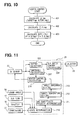
- FIG. 10 is a flow chart of a heater control of the oxygen sensor of the first embodiment
- FIG. 11 is a block diagram for controlling the element temperature of the oxygen sensor
- FIG. 12 is a CO reaction characteristic diagram of the oxygen sensor
- FIG. 13 is a NO reaction characteristic diagram of the oxygen sensor
- FIG. 14 is a flow chart of a target impedance setting routine in the first embodiment
- FIG. 15 is a map for setting the control duty of a heater
- FIG. 16 is a flow chart of a heater controlling routine in the first embodiment
- FIG. 17 presents time charts of the first embodiment
- FIG. 18 is a flow chart of a target impedance setting routine of a second embodiment of the invention.
- FIG. 19 presents time charts of the second embodiment.
- An internal combustion engine 11 is provided, at the most upstream portion of its intake pipe 12 , with an air cleaner 13 and, on the downstream side of the air cleaner 13 , with an air flow meter 14 for detecting the amount of intake air.
- On the downstream side of this air flow meter 14 there are disposed a throttle valve 15 and a throttle opening sensor 16 for detecting the degree of throttle opening.
- a surge tank 17 On the downstream side of the throttle valve 15 , moreover, there is disposed a surge tank 17 , which is provided with an intake pipe pressure sensor 18 for detecting an intake pipe pressure. On the other hand, the surge tank 17 is provided with an intake manifold 19 for introducing air into the individual cylinders of the engine 11 . In the vicinity of the intake port of each cylinder in the intake manifold 19 , there is attached a fuel injection valve 20 for injecting a fuel.
- an upstream catalyst 22 is formed to have such a relatively small capacity as is early warmed-up at a start to reduce the exhaust emissions at the start.
- the downstream catalyst 23 is formed to have such a relatively large capacity as can purify the exhaust gas sufficiently even in a high load range having a high exhaust gas flow rate.
- a linear air/fuel ratio sensor 24 for outputting a linear air/fuel ratio signal according to the air/fuel ratio of the exhaust gas.
- a first oxygen sensor 25 and a second oxygen sensor 26 having the well-known step-change characteristics (Z-characteristics), in which their individual outputs change relatively abruptly in the vicinity of the stoichiometric air/fuel ratio.
- the linear air/fuel ratio sensor and the oxygen sensor will be referred to as the air/fuel ratio sensor.
- a cooling water temperature sensor 27 for detecting the cooling water temperature
- a crank angle sensor 28 for detecting the engine speed NE.
- ECU 29 The outputs of these various sensors are inputted to an engine control unit (ECU) 29 .
- This ECU 29 is constructed mainly of a microcomputer, and feedback-controls the air/fuel ratio of the exhaust gas, for example, by executing a program stored in its internal ROM (or storage medium).
- FIG. 2 is a flow chart of an air/fuel ratio feedback control at the time when the linear air/fuel ratio sensor 24 is used as an air/fuel ratio sensor on the upstream side of the catalyst whereas the first oxygen sensor 25 and the second air/fuel ratio sensor 26 are interchanged and used as the air/fuel ratio sensor on the downstream side of the catalyst.
- FIG. 3 and FIG. 4 are flow charts of another air/fuel ratio feedback control of the case in which the second oxygen sensor 26 is used in addition to the linear air/fuel ratio sensor 24 and the first oxygen sensor 25 of FIG. 1.
- the downstream side oxygen sensor to be used for setting a target air/fuel ratio ⁇ TG is selected from the first oxygen sensor 25 and the second oxygen sensor 26 .
- the exhaust gas can be considerably purified with only the upstream catalyst 22 . Therefore, a better response to the air/fuel ratio control can be obtained by using the first oxygen sensor 25 as the downstream sensor to be used for setting the target air/fuel ratio ⁇ TG.
- the first oxygen sensor 25 As the exhaust gas flow rate becomes higher, however, the more exhaust gas component passes without being purified in the upstream catalyst 22 . It is, therefore, necessary to purify the exhaust gas by using both the upstream catalyst 22 and the downstream catalyst 23 effectively. In this case, it is preferable to make the air/fuel ratio feedback control considering the state of the downstream catalyst 23 , too. It is, therefore, preferable to use the second oxygen sensor 26 as the downstream sensor to be used for setting the target air/fuel ratio ⁇ TG.
- the condition for selecting the second oxygen sensor 26 as the downstream sensor to be used for setting the target air/fuel ratio ⁇ TG is: (1) that the delay time (or period) for the air/fuel ratio change of the exhaust gas discharged from the engine 11 (or the output change of the linear air/fuel ratio sensor 24 ) to appear in the output change of the first oxygen sensor 25 is shorter than a predetermined time (or predetermined period); or (2) that the intake air flow rate (or the exhaust gas flow rate) is no less than a predetermined value.
- the second oxygen sensor 26 is selected, if one of those two conditions (1) and (2) is satisfied, and the first oxygen sensor 25 is selected, if neither of them is satisfied.
- it is arbitrary to select the second oxygen sensor 26 if both the conditions (1) and (2) are satisfied.
- the target output voltage e.g. 0.45 V
- map for this integrated richness quantity ⁇ IR there are stored a map, as tabulated in the upper row of FIG. 5A, for the upstream catalyst downstream sensor (or the first oxygen sensor), and a map, as tabulated in the upper row of FIG. 5B, for the downstream catalyst downstream sensor (or the second oxygen sensor), so that one of the maps is selected according to the sensor employed.
- map characteristics of the integrated richness value ⁇ IR are set such that the integrated richness value ⁇ IR is smaller for the higher intake air flow QA, and are set in the region of a low intake air flow QA such that the map for the downstream catalyst downstream sensor has a slightly larger integrated richness value ⁇ IR than the map for the upstream catalyst downstream sensor.
- the routine advances to step 705 , at which the target air/fuel ratio ⁇ TG is corrected by ⁇ IR to the richer side, and this program is ended by storing the richness/leanness at this time (at step 713 ).
- step 703 NO
- step 706 a skip (proportional) quantity ⁇ SKR to the rich side is calculated according to a rich component storage OSTRich of the catalyst.
- the calculation of the rich component storage OSTRich is known (for instance, JP-A-2001-193521).
- the map characteristics of FIG. 6 are so set that the rich skip quantity ⁇ SKR may be the smaller as the absolute value of the rich component storage OSTRich becomes the less.
- the routine advances to step 707 , at which the target air/fuel ratio ⁇ TG is corrected by ⁇ XIR+ ⁇ SKR to the rich side, and this program is ended by storing the richness/leanness at this time (at step 713 ).
- step 702 If it is determined at step 702 that the output voltage VOX 2 of the oxygen sensor is rich, on the other hand, the routine advances to step 708 , at which it is determined whether or not the air/fuel ratio was also rich last time. If the air/fuel ratio was rich at the last time and at this time, the routine advances to step 709 , at which an integrated leanness value ⁇ IL is determined from the map shown in FIG. 5 in accordance with this intake air flow QA.
- the map for this integrated leanness quantity ⁇ IL there are set a map, as tabulated in the lower row of FIG. 5A, for the upstream catalyst downstream sensor (or the first oxygen sensor), and a map, as tabulated in the lower row of FIG. 5B, for the downstream catalyst downstream sensor (or the second oxygen sensor), so that one of the maps is selected according to the sensor selected as the downstream sensor.
- the map characteristics of the integrated leanness value ⁇ IL of FIG. 5A and FIG. 5B are set such that the integrated leanness value ⁇ IL is smaller for the higher intake air flow QA, and are set in the region of a low intake air flow QA such that the map for the downstream catalyst downstream sensor has a slightly larger integrated leanness value ⁇ IL than the map for the upstream catalyst downstream sensor.
- the routine advances to step 710 , at which the target air/fuel ratio ⁇ TG is corrected by ⁇ IL to a leaner side, and this program is ended by storing the richness/leanness at this time (at step 713 ).
- step 708 NO
- step 711 a proportional (ski) quantity ⁇ SKL to the lean side is determined from the map shown in FIG. 6 according to a lean component storage OSTLean of the catalyst.
- the calculation of the lean component storage OSTLean is known (for instance JP-A-2001-193521).
- the map characteristics of FIG. 6 are so set that the lean skip quantity ⁇ SKR may be smaller as the absolute value of the lean component storage OSTLean becomes less.
- the target air/fuel ratio ⁇ TG is corrected by ⁇ IL+ ⁇ SKL to the lean side, and this program is ended by storing the richness/leanness at this time (at step 713 ).
- the rich component storage OSTRich or the lean component storage OSTLean is lowered by the degradation of the catalysts 22 and 23 , as apparent from the map of FIG. 6, the rich skip quantity ⁇ SKR and the lean skip quantity ⁇ SKL are gradually set to lower values. Therefore, excessive corrections over the adsorption limits of the catalysts 22 and 23 are made to prevent the noxious contents in advance from being discharged.
- FIG. 3 and FIG. 4 Another example for setting the target air/fuel ratio is shown in FIG. 3 and FIG. 4.
- the ECU 29 executes the target air/fuel ratio setting program of FIG. 3 and the target output voltage setting program of FIG. 4 thereby to change the target output voltage TGOX of the first oxygen sensor 25 according to the output of the second oxygen sensor 26 when the first oxygen sensor 25 is selected as the downstream sensor to be used for setting the target air/fuel ratio ⁇ TG of the air/fuel ratio feedback control.
- FIG. 3 the steps of executing the operations similar to those of FIG. 2. The following description is given mainly on the points different from those of FIG. 2.
- the downstream sensor to be used for setting the target air/fuel ratio ⁇ TG is selected from the oxygen sensor 25 on the downstream side of the upstream catalyst 22 and the oxygen sensor 26 on the downstream side of the downstream catalyst 23 .
- the routine advances to step 714 , at which the target output voltage setting program of FIG. 4 is executed to set the target output voltage TGOX of the downstream sensor to be used for setting the target air/fuel ratio ⁇ TG.
- step 715 at which whether the air/fuel ratio is rich or lean is determined depending on whether the output voltage VOX 2 of the oxygen sensor selected is higher or lower than the target output voltage TGOX. According to this determination result, the target air/fuel ratio ⁇ TG is calculated at steps 703 to 713 by the above method, and this program is ended by storing the richness/leanness at this time.
- step 901 it is determined whether or not the first oxygen sensor 25 is selected as the downstream sensor to be used for setting the target air/fuel ratio ⁇ TG. If the first oxygen sensor 25 is selected as the downstream sensor to be used for setting the target air/fuel ratio ⁇ TG, the routine advances to step 902 , at which the target output voltage TGOX according to the present output voltage of the second oxygen sensor 26 is calculated from the map, in which the target output voltage TGOX is plotted against the output voltage of the second oxygen sensor 26 as a parameter.
- the map of the target output voltage TGOX is set as follows. Within a predetermined range ( ⁇ output voltage ⁇ ) in which the output voltage (or the air/fuel ratio of the outflow gas of the downstream catalyst 23 ) of the second oxygen sensor 26 is in the neighborhood of the stoichiometric air/fuel ratio, the target output voltage TGOX becomes the lower (or the leaner) as the output of the second oxygen sensor 26 becomes the higher (or the richer).
- the map is also set as follows. Within a region in which the output of the second oxygen sensor 26 is higher than the predetermined value ⁇ , moreover, the target output voltage TGOX takes a predetermined lower limit (e.g., 0.4 V). Within a region in which the output of the second oxygen sensor 26 is lower than the predetermined value ⁇ , the target output voltage TGOX takes an upper limit (e.g., 0.65 V).
- a predetermined lower limit e.g. 0.4 V
- the target output voltage TGOX Within a region in which the output of the second oxygen sensor 26 is lower than the predetermined value ⁇ , the target output voltage TGOX takes an upper limit (e.g., 0.65 V).
- the target output voltage TGOX of the first oxygen sensor 25 is set either within a range, in which the adsorption of the exhaust gas component of the downstream catalyst 23 is no more than a predetermined value or within a range, in which the air/fuel ratio of the exhaust gas to flow through the downstream catalyst 23 is within that of a predetermined purified wind.
- the routine advances from step 901 to step 903 , at which the target output voltage TGOX is set at a predetermined value (e.g., 0.45 V).
- a predetermined value e.g. 0.45 V.
- the ECU 29 is provided with a microcomputer (MC) 120 .
- This microcomputer 120 is connected with a host microcomputer 116 for realizing a fuel injection control, an ignition control and so on.
- the linear air/fuel ratio sensor 24 is mounted on the exhaust pipe 21 extending from the body of the engine 11 , and its output is detected by the microcomputer 120 .
- This microcomputer 120 is constructed of the well-known CPU, ROM, RAM, backup RAM and so on for executing various operations, and controls a heater control circuit 125 and a bias control circuit 140 in accordance with a predetermined control program.
- a bias command signal Vr as outputted from the microcomputer 120 , is inputted through a D/A converter 121 to the bias control circuit 140 .
- the output, as corresponding to the air/fuel ratio (or oxygen concentration) at times, of the linear air/fuel ratio sensor 24 is detected, and the detected value is inputted through an A/D converter 123 to the microcomputer 120 .
- the heater voltage and the heater current are detected by the heater control circuit 125 , and the detected values are inputted through the A/D converter 123 to the microcomputer 120 .
- the predetermined bias command signal Vr is applied to an element, and changes between predetermined times t 1 and t 2 , as shown in FIG. 8, that is, an element voltage ⁇ V and an element current ⁇ I are detected to detect the element impedance R from the following formula:
- the detected element impedance value is inputted to the microcomputer 120 .
- the element impedance has such an intense correlation to the element temperature, as shown in FIG. 9, so that the element temperature of the air/fuel ratio sensor can be controlled by duty-controlling the heater belonging to the air/fuel ratio sensor thereby to set the element impedance to a predetermined value.
- the element impedances are likewise detected, and the element temperatures of the oxygen sensors can be controlled by duty-controlling the heaters belonging to the first and second oxygen sensors 25 and 26 so that the element impedances may take predetermined values.
- this embodiment adopts a method, in which the PI (Proportional and Integral) control is made with the deviation between the element impedance actually detected and the target impedance calculated with the target element temperature, so that the element temperature of the first oxygen sensor 25 is controlled by the method.
- PI Proportional and Integral
- the program is processed at a predetermined timing.
- a deviation ⁇ imp
- an integrated value ⁇ imp
- the heater duty is calculated from the following formula by using the deviation, the integrated value, a proportional coefficient P1 and an integral coefficient I2.
- Heater Duty (%) P 1 ⁇ imp+I 2 ⁇ imp.
- the heater duty thus calculated is inputted to the heater control circuit, as designated at 125 in FIG. 7, so that the heater control of the first oxygen sensor 25 is made.
- the heater duty is the adjusted calorific value for controlling the temperature of the oxygen sensor element and is based on the electric power (W). For a constant temperature, it is desired to control the electric power to a constant value. In case the temperature is controlled by the heater duty, a correction is made to the reference voltage (e.g., 13.5 V), i.e., the electric power ⁇ (13.5/voltage) 2 so that the temperature may be prevented from being changed with the voltage supplied.
- the reference voltage e.g., 13.5 V
- the linear air/fuel ratio sensor 24 is mounted to protrude into the exhaust pipe 21 and is constructed mainly of a cover 132 , a sensor body 131 and a heater 135 .
- the cover 132 is formed into such a C-shaped section as has a number of pores in its peripheral wall for providing the communication between the inside and outside of the cover 132 .
- the sensor body 131 acting as the sensor element portion generates a voltage corresponding to either the oxygen concentration in the lean air/fuel ratio region or the concentration of the unburned gas (e.g., CO, HC and H 2 ) in the rich air/fuel ratio region.
- the heater 135 is housed in the atmospheric side electrode layer and heats the sensor body 131 (having an atmospheric side electrode layer 133 , a solid electrolyte layer 131 and an exhaust gas side electrode layer 134 ) with its calorific energy.
- the heater 135 has a sufficient calorific capacity for activating the sensor body 131 .
- the first oxygen sensor 25 and the second oxygen sensor 26 also have the similar constructions.
- the laminated type air/fuel ratio sensor having an integral structure of an element and a heater so as to improve the heater performance has been proposed in recent years.
- the invention can be applied not only to such sensor but also to any kind of air/fuel ratio sensor, if the sensor has electrodes arranged on a solid electrolyte element.
- the output of the exhaust gas component (e.g., the rich gas or the lean gas) discharged from the engine 11 by the first oxygen sensor (or the air/fuel ratio sensor) 25 is detected by an output detecting circuit 203 of the ECU 29 , and the air/fuel ratio ( ⁇ or A/F) control quantity is calculated by an air/fuel ratio control quantity calculating block 204 .
- the variation of the fuel injection rate (quantity) is determined by comparing the target voltage and the detected voltage.
- the fuel injection rate determined as the air/fuel ratio control quantity is fed to the injector 20 so that the fuel is injected in the desired rate.
- an impedance calculating block 202 calculates the element impedance
- a heater control quantity calculating block 214 calculates the heater control quantity with a deviation from the target impedance set by a target impedance setting block 213 , so that the heater is controlled to set the temperature of the sensor element of the first oxygen sensor 25 to a desired value.
- the target impedance is calculated by the following procedure.
- the determination of the running state is executed in a running state determining block 210 with the pieces of information indicating the running state of the engine and coming from the crank angle sensor 28 , the air flow meter 14 , the throttle opening sensor 16 , the cooling water temperature sensor 27 and so on.
- a specific gas sensitivity priority determining block 211 determines whether the composition of the exhaust gas discharged from the engine under the running condition prevailing or just after is mainly the rich gas or the lean gas.
- a target element temperature setting block 212 sets the target element temperature to 720° C., for example, so that the oxygen sensor element temperature may rise to improve the lean gas reactivity.
- the target element temperature setting block 212 sets the target element temperature to 420° C., for example, so that the oxygen sensor element temperature may fall to improve the rich gas reactivity.
- FIG. 12 shows the reactivity of O 2 sensor to carbon monoxide (CO) in nitrogen (N 2 ) as an electromotive force (emf) of the sensor.
- CO carbon monoxide
- N 2 nitrogen
- emf electromotive force
- FIG. 13 shows the reactivity of the O 2 sensor of the case in which nitrogen monoxide (NO) is introduced into an atmosphere of nitrogen (N 2 ) and carbon monoxide (CO).
- NO nitrogen monoxide
- N 2 nitrogen
- CO carbon monoxide
- the target impedance setting block 213 sets the target impedance with the relations, as shown in FIG. 15, between the element impedance and the element temperature.
- the heater control quantity calculating block 214 determines the heater control quantity by the comparison with the detected element impedance value.
- This control operation will be described with reference to the flow chart of FIG. 14.
- This routine is started at a predetermined timing such as a time or an injection synchronization, and it is determined at steps 301 and 302 whether or not the lean gas is major in the running state. Specifically, it is determined at step 301 whether or not the running state is under a high load (or a high air flow region). It is determined at step 302 whether or not the drive is at an acceleration. In the case of the high load running time and/or the acceleration, it is determined that the lean gas is major in the running state.
- step 301 and step 302 In case it is determined at step 301 and step 302 that the lean gas is major, the routine advances to step 303 , at which the target impedance is set to 20 ⁇ for a high element temperature (e.g., 720° C.). In case it is determined that the lean gas is not major (namely, in case the determinations of the two steps are No), on the contrary, the routine advances to steps 304 and 305 , at which it is determined whether or not the discharge of rich gas such as HC or CO is major in the running condition.
- a high element temperature e.g., 720° C.
- step 304 it is determined at step 304 whether or not the engine temperature is low, and it is determined at step 305 whether or not the running condition is idle or light load. In case the engine temperature is low and in case the running condition is idle and light load, it is determined that the rich gas is major.
- step 304 and step 305 that the rich gas is major (in case the answers are YES)
- the routine advances to step 306 , at which the target impedance is set to 1,000 ⁇ for a low element temperature (e.g., 420° C.).
- a low element temperature e.g., 420° C.
- the target impedance is set to 100 ⁇ at step 307 for the normal target temperature (e.g., 570° C.).
- the O 2 sensor control to be executed for the target impedances thus set can be achieved by the method thus far described.
- the control achieving method proposed herein need not be the heater control for calculating the element impedance but may be the well-known heater control without calculating the element impedance.
- the invention can also be applied to the case in which the control is made on the basis of the heater control quantity (in the duty or electric power) set under each predetermined engine running condition.
- FIG. 15 shows a control map for setting the heater duty on the basis of the engine speed and the engine load.
- the fundamental controlling heater duty map of FIG. 15 is a map to be used at normal time. In this embodiment, not only the normal map but also a low temperature controlling heater duty map and a high temperature controller heater duty map are provided in correspondence with a demand for detecting the gas composition of the engine. These maps are interchanged for use according to the running state or the like.
- the invention can be embodied in the system, which merely selects the heater duty map to be used from the target element temperature results set by the target element temperature setting block 212 of FIG. 11 but does not calculate the element impedance.
- the element high temperature controlling heater duty map has a high value (in the duty or electric power) with respect to the fundamental controlling heater duty map
- the element low temperature controlling heater duty map has a low value (in the duty or electric power) with respect to the fundamental controlling heater duty map.
- the element low temperature control or the element high temperature control can also be achieved by increasing or decreasing the predetermined duty with respect to the fundamental control heater duty map.
- step 601 it is determined at step 601 whether the exhaust gas is in the rich gas atmosphere or needs an increased sensitivity to CO gas. If determined necessary, the routine advances to step 603 , at which the low temperature controlling heater duty map is selected to control the element to a low temperature.
- step 601 In case it is determined at step 601 that the increased sensitivity to the CO gas is unnecessary, the routine advances to step 602 , at which whether the exhaust gas is in the lean gas atmosphere or needs an increased sensitivity to NO gas. If it is determined that the increased sensitivity is necessary, the routine advances to step 604 , at which the high temperature controlling heater duty map is selected to control the element to a high temperature. In case it is determined at both steps 601 and 602 that the increased sensitivity is unnecessary, the routine advances to step 605 , at which the fundamental controlling heater duty map is selected.
- FIG. 17 presents the time charts at the time when the vehicle is driven at the running speed shown as (a).
- the engine Before time T 1 , the engine is started to start its warming-up to raise the engine temperature (b).
- the low load determination flag of the idle state is turned from ON to OFF (d).
- the acceleration determination flag is turned from OFF to ON (g).
- the heater control is switched from the low temperature control to the high temperature control. Therefore, the target element impedance R is controlled to 20 ⁇ of the target of the high temperature control, and the element temperature R is controlled to 720° C. as shown as (i) and (j).
- the low load determination flag is turned from OFF to ON (d).
- the target impedance is controlled to 1,000 ⁇ for the low temperature of the first oxygen sensor element, and the rich gas is detected more sensibly, so that a slightly lean air/fuel ratio control can be made to set the target air/fuel ratio slightly lean with respect to the stoichiometric air/fuel ratio.
- the low load determination flag is turned from ON to OFF (c), and the acceleration determination flag is turned from OFF to ON (g).
- the heater control of the first oxygen sensor 25 is switched to the high temperature control so as to detect the NOx (i.e., the lean gas), as mostly discharged at the acceleration, highly precisely.
- the target impedance is set to 20 ⁇ , and the element temperature becomes high (e.g., 720° C.) so that the reactivity to the lean gas is better improved. Therefore, the output (k) of the first oxygen sensor 25 can react instantly, as shown, on the NOx discharge at the acceleration, so that the air/fuel ratio correction quantity ⁇ c (l) is instantly increased.
- the discharge of NOx can be reduced more by executing the air/fuel ratio control than the related art indicated with a dotted line in (m) so that the improvement in the emission ability can be improved.
- the running state is switched to the high load so that the high load determination flag (f) is turned from OFF to ON with the intake air flow or the throttle opening.
- the heater low temperature control is executed as at times T 4 and T 6 , and the O 2 sensor can enhance the reaction sensitivity of the lean gas so that the lean output (or the low voltage output) is instantly outputted, as shown, with the sensor output (k).
- This lean output is detected by the ECU 29 so that the air/fuel ratio correction quantity (l) is instantly increased to reduce the discharge of the NOx (m).
- the heater control is made at the three stages of the high, low and normal temperatures, but the three stages are not necessarily essential.
- the oxygen sensor element temperature can be changed to other multiple stages with a view to improving the desired exhaust gas detection precision.
- the target impedance setting routine is differentiated from that in the first embodiment (FIG. 14), as shown in FIG. 18.
- the flow chart of FIG. 18 is started at a predetermined timing.
- this routine it is determined at step 501 whether or not the fuel supply is resumed from the fuel cut-off (F/C).
- step 502 moreover, it is determined whether or not the fuel supply is being increased due to the return from the fuel cut-off.
- the routine advances to step 506 , at which the target impedance R is set to 100 ⁇ (e.g., 570° C.) for the normal temperature control.
- step 503 it is determined whether or not the first oxygen sensor output VOX is less than 0.45 V (stoichiometry). In case of more than 0.45 V, it is determined that the catalyst is enriched by the increased fuel, and the routine advances to step 505 , at which the fuel increase is instantly stopped. After this, the routine advances to step 506 , at which the target impedance is set to control the O 2 sensor element to the normal temperature.
- step 503 In case it is determined at step 503 that the O 2 sensor output VOX is less than 0.45 V, it is determined that much O 2 still exists in the catalyst.
- the heater control is switched at step 504 to the low temperature one, in which the O 2 sensor element can be used at a low temperature for a higher sensitivity to the rich gas.
- the first oxygen sensor output VOX takes a low voltage indicating a lean air/fuel ratio.
- the state, in which much O 2 is fed to the catalyst is switched to a neutral point so that the fuel increase following the return from the fuel cut-off is executed.
- some engine is controlled to have a small increase of fuel following the return from the fuel cut-off while avoiding the rich gas discharge.
- the O 2 sensor element temperature had better be set so high as to improve the reactivity to the lean gas (NOx).
- the first and second embodiments have been described on the first oxygen sensor 25 , but the invention can be likewise applied to the air/fuel ratio sensor 24 and the second oxygen sensor 26 .
- the invention can be applied to an exhaust sensor for detecting a gas reaction at its electrode and does not limit the kind of the exhaust sensor.
Landscapes
- Engineering & Computer Science (AREA)
- Chemical & Material Sciences (AREA)
- Combustion & Propulsion (AREA)
- Mechanical Engineering (AREA)
- General Engineering & Computer Science (AREA)
- Health & Medical Sciences (AREA)
- Chemical Kinetics & Catalysis (AREA)
- Toxicology (AREA)
- Electrical Control Of Air Or Fuel Supplied To Internal-Combustion Engine (AREA)
- Combined Controls Of Internal Combustion Engines (AREA)
Abstract
Description
- This application is based on and incorporates herein by reference Japanese Patent Application No. 2002-121306 filed on Apr. 23, 2002.
- The present invention relates to an exhaust gas purifying system for an internal combustion engine, which is provided with a heater control device for controlling a heater attached to a sensor for detecting the air/fuel ratio in the exhaust gas of the internal combustion engine.
- In an exhaust gas purifying system, which is provided with an air/fuel ratio sensor upstream of a catalyst disposed on the exhaust pipe of the internal combustion engine so that the output of the air/fuel ratio sensor may approach a target air/fuel ratio. Moreover, another air/fuel ratio sensor is further disposed downstream of the catalyst so that the target air/fuel ratio upstream of the catalyst may be corrected on the basis of the output of that downstream air/fuel ratio sensor.
- However, in this system the output characteristics are varied even at the same air/fuel ratio by the temperature change of a solid electrolyte element (or a sensor element) of the air/fuel ratio sensor. In JP-A-9-127035, for example, therefore, the detection precision is improved by controlling the electric current of a heater for heating the sensor element thereby to make the element temperature of the air/fuel ratio sensor constant. In U.S. Pat. No. 5,263,358, moreover, the detection precision is improved by correcting the sensor output characteristics according to the sensor element temperature of the air/fuel ratio sensor. These technologies can improve the detection precision to the air/fuel ratio but not the detection precision (or reaction) to a specific gas.
- Therefore, the invention contemplates to provide an exhaust gas purifying system for an internal combustion engine, which is enabled to detect a specific gas relatively inexpensively by intentionally changing a detection sensitivity (or reaction) of an air/fuel ratio sensor to the specific gas.
- In order to achieve this object, a system of the invention gives an air/fuel ratio detecting sensor made by arranging an electrode at a solid electrolyte element, for detecting the air/fuel ratio in the exhaust gas from the engine, priority in sensitivity to a specific gas in the exhaust gas. In order to change this detection sensitivity to the specific exhaust gas, the temperature of the solid electrolyte element is adjusted. As a result, it is possible to improve the detection characteristic of an exhaust gas component to be reduced or detected.
- The system of the invention, moreover, adjusts the temperature of the solid electrolyte element in accordance with the running state of the engine so as to change the detection sensitivity of an air/fuel ratio detecting sensor made by arranging an electrode at the solid electrolyte element, for detecting the air/fuel ratio in the exhaust gas from the engine, to the specific exhaust gas. As a result, it is possible to improve the detection characteristic to the exhaust gas component to be reduced or detected.
- The above and other objects, features and advantages of the present invention will become more apparent from the following detailed description made with reference to the accompanying drawings.
- FIG. 1 is a schematic diagram of an exhaust purifying system of the invention;
- FIG. 2 is a flow chart of a target air/fuel ratio setting routine of a first embodiment of the invention;
- FIG. 3 is a flow chart of a target air/fuel ratio setting routine of a modification of the first embodiment;
- FIG. 4 is a flowchart of a target output voltage routine of a first oxygen sensor in the first embodiment;
- FIGS. 5A and 5B present maps for setting an integrated richness quantity and an integrated leanness quantity in the first embodiment;
- FIG. 6 is a map for setting a skip quantity in the first embodiment;
- FIG. 7 is a schematic diagram for detecting an air/fuel ratio and impedance;
- FIG. 8 is a time chart at the time of detecting the impedance;
- FIG. 9 is an impedance characteristic diagram of an oxygen sensor;
- FIG. 10 is a flow chart of a heater control of the oxygen sensor of the first embodiment;
- FIG. 11 is a block diagram for controlling the element temperature of the oxygen sensor;
- FIG. 12 is a CO reaction characteristic diagram of the oxygen sensor;
- FIG. 13 is a NO reaction characteristic diagram of the oxygen sensor;
- FIG. 14 is a flow chart of a target impedance setting routine in the first embodiment;
- FIG. 15 is a map for setting the control duty of a heater;
- FIG. 16 is a flow chart of a heater controlling routine in the first embodiment;
- FIG. 17 presents time charts of the first embodiment;
- FIG. 18 is a flow chart of a target impedance setting routine of a second embodiment of the invention; and
- FIG. 19 presents time charts of the second embodiment.
- [First Embodiment]
- First of all, the schematic construction of an engine control system will be described with reference to FIG. 1. An
internal combustion engine 11 is provided, at the most upstream portion of itsintake pipe 12, with anair cleaner 13 and, on the downstream side of theair cleaner 13, with anair flow meter 14 for detecting the amount of intake air. On the downstream side of thisair flow meter 14, there are disposed athrottle valve 15 and athrottle opening sensor 16 for detecting the degree of throttle opening. - On the downstream side of the
throttle valve 15, moreover, there is disposed asurge tank 17, which is provided with an intakepipe pressure sensor 18 for detecting an intake pipe pressure. On the other hand, thesurge tank 17 is provided with anintake manifold 19 for introducing air into the individual cylinders of theengine 11. In the vicinity of the intake port of each cylinder in theintake manifold 19, there is attached afuel injection valve 20 for injecting a fuel. - Midway of an exhaust pipe 21 (or an exhaust gas passage) of the
engine 11, on the other hand, there are disposed in tandem anupstream catalyst 22 and adownstream catalyst 23 for reducing noxious contents (CO, HC, NOx and so on) in the exhaust gas. In this case, theupstream catalyst 22 is formed to have such a relatively small capacity as is early warmed-up at a start to reduce the exhaust emissions at the start. On the contrary, thedownstream catalyst 23 is formed to have such a relatively large capacity as can purify the exhaust gas sufficiently even in a high load range having a high exhaust gas flow rate. - On the upstream side of the
upstream catalyst 22, moreover, there is disposed a linear air/fuel ratio sensor 24 for outputting a linear air/fuel ratio signal according to the air/fuel ratio of the exhaust gas. On the downstream side of theupstream catalyst 22 and on the downstream side of thedownstream catalyst 23, respectively, there are disposed afirst oxygen sensor 25 and asecond oxygen sensor 26 having the well-known step-change characteristics (Z-characteristics), in which their individual outputs change relatively abruptly in the vicinity of the stoichiometric air/fuel ratio. The linear air/fuel ratio sensor and the oxygen sensor will be referred to as the air/fuel ratio sensor. To the cylinder block of theengine 11, moreover, there are attached a coolingwater temperature sensor 27 for detecting the cooling water temperature and acrank angle sensor 28 for detecting the engine speed NE. - The outputs of these various sensors are inputted to an engine control unit (ECU) 29. This ECU 29 is constructed mainly of a microcomputer, and feedback-controls the air/fuel ratio of the exhaust gas, for example, by executing a program stored in its internal ROM (or storage medium).
- FIG. 2 is a flow chart of an air/fuel ratio feedback control at the time when the linear air/
fuel ratio sensor 24 is used as an air/fuel ratio sensor on the upstream side of the catalyst whereas thefirst oxygen sensor 25 and the second air/fuel ratio sensor 26 are interchanged and used as the air/fuel ratio sensor on the downstream side of the catalyst. - On the other hand, FIG. 3 and FIG. 4 are flow charts of another air/fuel ratio feedback control of the case in which the
second oxygen sensor 26 is used in addition to the linear air/fuel ratio sensor 24 and thefirst oxygen sensor 25 of FIG. 1. - Referring first to FIG. 2, when this program is started, at
first step 701, the downstream side oxygen sensor to be used for setting a target air/fuel ratio λTG is selected from thefirst oxygen sensor 25 and thesecond oxygen sensor 26. - At a low load running time of a low exhaust gas flow, for example, the exhaust gas can be considerably purified with only the
upstream catalyst 22. Therefore, a better response to the air/fuel ratio control can be obtained by using thefirst oxygen sensor 25 as the downstream sensor to be used for setting the target air/fuel ratio λTG. As the exhaust gas flow rate becomes higher, however, the more exhaust gas component passes without being purified in theupstream catalyst 22. It is, therefore, necessary to purify the exhaust gas by using both theupstream catalyst 22 and thedownstream catalyst 23 effectively. In this case, it is preferable to make the air/fuel ratio feedback control considering the state of thedownstream catalyst 23, too. It is, therefore, preferable to use thesecond oxygen sensor 26 as the downstream sensor to be used for setting the target air/fuel ratio λTG. - As there becomes the shorter the delay time for the change in the air/fuel ratio of the exhaust gas discharged from the engine 11 (or the output change in the air/
fuel ratio sensor 24 on the upstream side of the upstream catalyst 22) to appear in the output change of thefirst oxygen sensor 25, on the other hand, it is meant that the more exhaust gas component passes without being purified in the upstream catalyst 22 (or the purification efficiency degrades the lower). In case the delay time of the output change of thefirst oxygen sensor 25 is short, therefore, it is preferable to use the output of thesecond oxygen sensor 26 as the downstream sensor to be used for setting the target air/fuel ratio λTG. - Therefore, the condition for selecting the
second oxygen sensor 26 as the downstream sensor to be used for setting the target air/fuel ratio λTG is: (1) that the delay time (or period) for the air/fuel ratio change of the exhaust gas discharged from the engine 11 (or the output change of the linear air/fuel ratio sensor 24) to appear in the output change of thefirst oxygen sensor 25 is shorter than a predetermined time (or predetermined period); or (2) that the intake air flow rate (or the exhaust gas flow rate) is no less than a predetermined value. - The
second oxygen sensor 26 is selected, if one of those two conditions (1) and (2) is satisfied, and thefirst oxygen sensor 25 is selected, if neither of them is satisfied. Here, it is arbitrary to select thesecond oxygen sensor 26, if both the conditions (1) and (2) are satisfied. - After the downstream sensor to be used for setting the target air/fuel ratio λTG is thus selected, the routine advances to step 702, at which whether the air/fuel ratio is rich or lean is determined depending upon whether the output voltage VOX2 of the selected oxygen sensor is higher or lower than the target output voltage (e.g., 0.45 V), which corresponds to the stoichiometric air/fuel ratio (λ=1). If lean, the routine advances to step 703, at which it is determined whether or not the air/fuel ratio was also lean at the last time. If lean not only last time but also at this time, the routine advances to step 704, at which an integrated richness quantity λIR is calculated from the map in accordance with the present intake air flow QA.
- As the map for this integrated richness quantity λIR, there are stored a map, as tabulated in the upper row of FIG. 5A, for the upstream catalyst downstream sensor (or the first oxygen sensor), and a map, as tabulated in the upper row of FIG. 5B, for the downstream catalyst downstream sensor (or the second oxygen sensor), so that one of the maps is selected according to the sensor employed.
- These map characteristics of the integrated richness value λIR are set such that the integrated richness value λIR is smaller for the higher intake air flow QA, and are set in the region of a low intake air flow QA such that the map for the downstream catalyst downstream sensor has a slightly larger integrated richness value λIR than the map for the upstream catalyst downstream sensor. After the integrated richness value λIR is calculated, the routine advances to step 705, at which the target air/fuel ratio λTG is corrected by λIR to the richer side, and this program is ended by storing the richness/leanness at this time (at step 713).
- In case the air/fuel ratio turns lean from the rich condition of the last time, on the other hand, the routine advances from step 703 (NO) to step 706, at which a skip (proportional) quantity λSKR to the rich side is calculated according to a rich component storage OSTRich of the catalyst. Here, the calculation of the rich component storage OSTRich is known (for instance, JP-A-2001-193521).
- The map characteristics of FIG. 6 are so set that the rich skip quantity λSKR may be the smaller as the absolute value of the rich component storage OSTRich becomes the less. After the skip quantity λSKR was calculated, the routine advances to step 707, at which the target air/fuel ratio λTG is corrected by λXIR+λSKR to the rich side, and this program is ended by storing the richness/leanness at this time (at step 713).
- If it is determined at
step 702 that the output voltage VOX2 of the oxygen sensor is rich, on the other hand, the routine advances to step 708, at which it is determined whether or not the air/fuel ratio was also rich last time. If the air/fuel ratio was rich at the last time and at this time, the routine advances to step 709, at which an integrated leanness value λIL is determined from the map shown in FIG. 5 in accordance with this intake air flow QA. As the map for this integrated leanness quantity λIL, there are set a map, as tabulated in the lower row of FIG. 5A, for the upstream catalyst downstream sensor (or the first oxygen sensor), and a map, as tabulated in the lower row of FIG. 5B, for the downstream catalyst downstream sensor (or the second oxygen sensor), so that one of the maps is selected according to the sensor selected as the downstream sensor. - The map characteristics of the integrated leanness value λIL of FIG. 5A and FIG. 5B are set such that the integrated leanness value λIL is smaller for the higher intake air flow QA, and are set in the region of a low intake air flow QA such that the map for the downstream catalyst downstream sensor has a slightly larger integrated leanness value λIL than the map for the upstream catalyst downstream sensor. After the integrated leanness value λIL is calculated, the routine advances to step 710, at which the target air/fuel ratio λTG is corrected by λIL to a leaner side, and this program is ended by storing the richness/leanness at this time (at step 713).
- In case the air/fuel ratio turns rich from the lean condition of the last time, on the other hand, the routine advances from step 708 (NO) to step 711, at which a proportional (ski) quantity λSKL to the lean side is determined from the map shown in FIG. 6 according to a lean component storage OSTLean of the catalyst. Here, the calculation of the lean component storage OSTLean is known (for instance JP-A-2001-193521).
- The map characteristics of FIG. 6 are so set that the lean skip quantity λSKR may be smaller as the absolute value of the lean component storage OSTLean becomes less. After this, at
step 712, the target air/fuel ratio λTG is corrected by λIL+λSKL to the lean side, and this program is ended by storing the richness/leanness at this time (at step 713). - When the rich component storage OSTRich or the lean component storage OSTLean is lowered by the degradation of the
catalysts catalysts - Another example for setting the target air/fuel ratio is shown in FIG. 3 and FIG. 4.
- The
ECU 29 executes the target air/fuel ratio setting program of FIG. 3 and the target output voltage setting program of FIG. 4 thereby to change the target output voltage TGOX of thefirst oxygen sensor 25 according to the output of thesecond oxygen sensor 26 when thefirst oxygen sensor 25 is selected as the downstream sensor to be used for setting the target air/fuel ratio λTG of the air/fuel ratio feedback control. - Here in FIG. 3, the steps of executing the operations similar to those of FIG. 2. The following description is given mainly on the points different from those of FIG. 2.
- In the target air/fuel ratio setting program of FIG. 3, at the
first step 701, the downstream sensor to be used for setting the target air/fuel ratio λTG is selected from theoxygen sensor 25 on the downstream side of theupstream catalyst 22 and theoxygen sensor 26 on the downstream side of thedownstream catalyst 23. After this, the routine advances to step 714, at which the target output voltage setting program of FIG. 4 is executed to set the target output voltage TGOX of the downstream sensor to be used for setting the target air/fuel ratio λTG. - After this, the routine advances to step 715, at which whether the air/fuel ratio is rich or lean is determined depending on whether the output voltage VOX2 of the oxygen sensor selected is higher or lower than the target output voltage TGOX. According to this determination result, the target air/fuel ratio λTG is calculated at
steps 703 to 713 by the above method, and this program is ended by storing the richness/leanness at this time. - In the target output voltage setting program of FIG. 4 to be executed at
step 714 of FIG. 3, atfirst step 901, it is determined whether or not thefirst oxygen sensor 25 is selected as the downstream sensor to be used for setting the target air/fuel ratio λTG. If thefirst oxygen sensor 25 is selected as the downstream sensor to be used for setting the target air/fuel ratio λTG, the routine advances to step 902, at which the target output voltage TGOX according to the present output voltage of thesecond oxygen sensor 26 is calculated from the map, in which the target output voltage TGOX is plotted against the output voltage of thesecond oxygen sensor 26 as a parameter. - In this case, the map of the target output voltage TGOX is set as follows. Within a predetermined range (β≦output voltage≦α) in which the output voltage (or the air/fuel ratio of the outflow gas of the downstream catalyst 23) of the
second oxygen sensor 26 is in the neighborhood of the stoichiometric air/fuel ratio, the target output voltage TGOX becomes the lower (or the leaner) as the output of thesecond oxygen sensor 26 becomes the higher (or the richer). - The map is also set as follows. Within a region in which the output of the
second oxygen sensor 26 is higher than the predetermined value α, moreover, the target output voltage TGOX takes a predetermined lower limit (e.g., 0.4 V). Within a region in which the output of thesecond oxygen sensor 26 is lower than the predetermined value β, the target output voltage TGOX takes an upper limit (e.g., 0.65 V). - As a result, the target output voltage TGOX of the
first oxygen sensor 25 is set either within a range, in which the adsorption of the exhaust gas component of thedownstream catalyst 23 is no more than a predetermined value or within a range, in which the air/fuel ratio of the exhaust gas to flow through thedownstream catalyst 23 is within that of a predetermined purified wind. - In case the
second oxygen sensor 26 is selected as the downstream sensor to be used for setting the target air/fuel ratio λTG, on the other hand, the routine advances fromstep 901 to step 903, at which the target output voltage TGOX is set at a predetermined value (e.g., 0.45 V). The above target output voltage setting program performs a second feedback control. - As shown in FIG. 7, the
ECU 29 is provided with a microcomputer (MC) 120. Thismicrocomputer 120 is connected with ahost microcomputer 116 for realizing a fuel injection control, an ignition control and so on. The linear air/fuel ratio sensor 24 is mounted on theexhaust pipe 21 extending from the body of theengine 11, and its output is detected by themicrocomputer 120. Thismicrocomputer 120 is constructed of the well-known CPU, ROM, RAM, backup RAM and so on for executing various operations, and controls aheater control circuit 125 and abias control circuit 140 in accordance with a predetermined control program. - Here, a bias command signal Vr, as outputted from the
microcomputer 120, is inputted through a D/A converter 121 to thebias control circuit 140. Moreover, the output, as corresponding to the air/fuel ratio (or oxygen concentration) at times, of the linear air/fuel ratio sensor 24 is detected, and the detected value is inputted through an A/D converter 123 to themicrocomputer 120. Still moreover, the heater voltage and the heater current are detected by theheater control circuit 125, and the detected values are inputted through the A/D converter 123 to themicrocomputer 120. - On the other hand, the predetermined bias command signal Vr is applied to an element, and changes between predetermined times t 1 and t2, as shown in FIG. 8, that is, an element voltage ΔV and an element current ΔI are detected to detect the element impedance R from the following formula:
- Impedance R=ΔV/ΔI.
- The detected element impedance value is inputted to the
microcomputer 120. The element impedance has such an intense correlation to the element temperature, as shown in FIG. 9, so that the element temperature of the air/fuel ratio sensor can be controlled by duty-controlling the heater belonging to the air/fuel ratio sensor thereby to set the element impedance to a predetermined value. - For the
first oxygen sensor 25 and thesecond oxygen sensor 26, too, the element impedances are likewise detected, and the element temperatures of the oxygen sensors can be controlled by duty-controlling the heaters belonging to the first andsecond oxygen sensors - As shown in FIG. 10, this embodiment adopts a method, in which the PI (Proportional and Integral) control is made with the deviation between the element impedance actually detected and the target impedance calculated with the target element temperature, so that the element temperature of the
first oxygen sensor 25 is controlled by the method. - This detail will be described with reference to the flow chart of FIG. 10. In this flow chart, the program is processed at a predetermined timing. At
first step 401, there is calculated a deviation (Δimp) between the target impedance calculated from the target element temperature and the actual element impedance detected by the element impedance detecting circuit. Atstep 402, there is calculated an integrated value (ΣΔimp) of the impedance deviation for executing the integral control. Atstep 403, the heater duty is calculated from the following formula by using the deviation, the integrated value, a proportional coefficient P1 and an integral coefficient I2. - Heater Duty (%)=P1×Δimp+I2×ΣΔimp.
- The heater duty thus calculated is inputted to the heater control circuit, as designated at 125 in FIG. 7, so that the heater control of the
first oxygen sensor 25 is made. - Here, the heater duty is the adjusted calorific value for controlling the temperature of the oxygen sensor element and is based on the electric power (W). For a constant temperature, it is desired to control the electric power to a constant value. In case the temperature is controlled by the heater duty, a correction is made to the reference voltage (e.g., 13.5 V), i.e., the electric power×(13.5/voltage) 2 so that the temperature may be prevented from being changed with the voltage supplied.
- In FIG. 7, the linear air/
fuel ratio sensor 24 is mounted to protrude into theexhaust pipe 21 and is constructed mainly of acover 132, asensor body 131 and aheater 135. Thecover 132 is formed into such a C-shaped section as has a number of pores in its peripheral wall for providing the communication between the inside and outside of thecover 132. Thesensor body 131 acting as the sensor element portion generates a voltage corresponding to either the oxygen concentration in the lean air/fuel ratio region or the concentration of the unburned gas (e.g., CO, HC and H2) in the rich air/fuel ratio region. - The
heater 135 is housed in the atmospheric side electrode layer and heats the sensor body 131 (having an atmosphericside electrode layer 133, asolid electrolyte layer 131 and an exhaust gas side electrode layer 134) with its calorific energy. Theheater 135 has a sufficient calorific capacity for activating thesensor body 131. Moreover, thefirst oxygen sensor 25 and thesecond oxygen sensor 26 also have the similar constructions. - Here, the laminated type air/fuel ratio sensor having an integral structure of an element and a heater so as to improve the heater performance has been proposed in recent years. The invention can be applied not only to such sensor but also to any kind of air/fuel ratio sensor, if the sensor has electrodes arranged on a solid electrolyte element.
- The control operation of the first embodiment will be described with reference to the system block diagram shown in FIG. 11. It is assumed here that the invention is applied to the
first oxygen sensor 25 arranged just downstream of the upstream catalyst of FIG. 1. - The output of the exhaust gas component (e.g., the rich gas or the lean gas) discharged from the
engine 11 by the first oxygen sensor (or the air/fuel ratio sensor) 25 is detected by anoutput detecting circuit 203 of theECU 29, and the air/fuel ratio (λ or A/F) control quantity is calculated by an air/fuel ratio controlquantity calculating block 204. Here, the variation of the fuel injection rate (quantity) is determined by comparing the target voltage and the detected voltage. The fuel injection rate determined as the air/fuel ratio control quantity is fed to theinjector 20 so that the fuel is injected in the desired rate. - As described with reference to FIG. 7 and FIG. 8, an
impedance calculating block 202 calculates the element impedance, and a heater controlquantity calculating block 214 calculates the heater control quantity with a deviation from the target impedance set by a targetimpedance setting block 213, so that the heater is controlled to set the temperature of the sensor element of thefirst oxygen sensor 25 to a desired value. - Here, the target impedance is calculated by the following procedure. The determination of the running state is executed in a running
state determining block 210 with the pieces of information indicating the running state of the engine and coming from thecrank angle sensor 28, theair flow meter 14, thethrottle opening sensor 16, the coolingwater temperature sensor 27 and so on. On the basis of this running state determination, a specific gas sensitivitypriority determining block 211 determines whether the composition of the exhaust gas discharged from the engine under the running condition prevailing or just after is mainly the rich gas or the lean gas. - In case the specific gas sensitivity
priority determining block 211 determines that the lean gas is major in the state where the NOx is easily produced as in a high load or at an acceleration, a target elementtemperature setting block 212 sets the target element temperature to 720° C., for example, so that the oxygen sensor element temperature may rise to improve the lean gas reactivity. In case the specific gas sensitivitypriority determining block 211 determines that the rich gas is (or will be) major in the state where the HC or CO is easily produced as at a low temperature, in a low load or at a deceleration, on the contrary, the target elementtemperature setting block 212 sets the target element temperature to 420° C., for example, so that the oxygen sensor element temperature may fall to improve the rich gas reactivity. - The reactivity of the rich and lean gases of the oxygen sensors will be described with reference to the characteristic diagrams of FIG. 12 and FIG. 13.
- FIG. 12 shows the reactivity of O 2 sensor to carbon monoxide (CO) in nitrogen (N2) as an electromotive force (emf) of the sensor. As shown, the reactivity is high to minute CO at a low element temperature, but the reactivity to a low concentration of CO falls as the element temperature rises. This is because the reactivity at the O2 sensor electrode to CO has temperature characteristics so that the following reactions at a low element temperature are promoted to deprive O2:
- CO (Adsorption)+½O2− (Adsorption)
- CO2+2e −.

- On the other hand, FIG. 13 shows the reactivity of the O 2 sensor of the case in which nitrogen monoxide (NO) is introduced into an atmosphere of nitrogen (N2) and carbon monoxide (CO). As shown, the O2 sensor reacts with fine NO in an element high temperature state but less with a low concentration of NO as the element temperature becomes lower. This is because the following reactions occur on the O2 sensor electrode surface and the electrode so that the combustion with the rich gas (CO) and the decomposition of NO at the electrode are more promoted in a high temperature region than in a low temperature region thereby to lower the electromotive force on the low concentration side:
- CO+NO→CO2+N2, and
- 2NO+4e→N2+2O2−.
- On the basis of the target temperature set by the target element
temperature setting block 212 of FIG. 11, the targetimpedance setting block 213 sets the target impedance with the relations, as shown in FIG. 15, between the element impedance and the element temperature. The heater controlquantity calculating block 214 determines the heater control quantity by the comparison with the detected element impedance value. - This control operation will be described with reference to the flow chart of FIG. 14. This routine is started at a predetermined timing such as a time or an injection synchronization, and it is determined at
steps step 301 whether or not the running state is under a high load (or a high air flow region). It is determined atstep 302 whether or not the drive is at an acceleration. In the case of the high load running time and/or the acceleration, it is determined that the lean gas is major in the running state. - In case it is determined at
step 301 and step 302 that the lean gas is major, the routine advances to step 303, at which the target impedance is set to 20 Ω for a high element temperature (e.g., 720° C.). In case it is determined that the lean gas is not major (namely, in case the determinations of the two steps are No), on the contrary, the routine advances tosteps - Specifically, it is determined at
step 304 whether or not the engine temperature is low, and it is determined atstep 305 whether or not the running condition is idle or light load. In case the engine temperature is low and in case the running condition is idle and light load, it is determined that the rich gas is major. - In case it is thus determined at
step 304 and step 305 that the rich gas is major (in case the answers are YES), the routine advances to step 306, at which the target impedance is set to 1,000 Ω for a low element temperature (e.g., 420° C.). - In case the answers of all
steps step 307 for the normal target temperature (e.g., 570° C.). - The O 2 sensor control to be executed for the target impedances thus set can be achieved by the method thus far described. Moreover, the control achieving method proposed herein need not be the heater control for calculating the element impedance but may be the well-known heater control without calculating the element impedance. The invention can also be applied to the case in which the control is made on the basis of the heater control quantity (in the duty or electric power) set under each predetermined engine running condition.
- An example of this application will be described with reference to FIG. 15 and FIG. 16.
- FIG. 15 shows a control map for setting the heater duty on the basis of the engine speed and the engine load. The fundamental controlling heater duty map of FIG. 15 is a map to be used at normal time. In this embodiment, not only the normal map but also a low temperature controlling heater duty map and a high temperature controller heater duty map are provided in correspondence with a demand for detecting the gas composition of the engine. These maps are interchanged for use according to the running state or the like.
- With these maps, the invention can be embodied in the system, which merely selects the heater duty map to be used from the target element temperature results set by the target element
temperature setting block 212 of FIG. 11 but does not calculate the element impedance. - Here, the element high temperature controlling heater duty map has a high value (in the duty or electric power) with respect to the fundamental controlling heater duty map, and the element low temperature controlling heater duty map has a low value (in the duty or electric power) with respect to the fundamental controlling heater duty map. Moreover, the element low temperature control or the element high temperature control can also be achieved by increasing or decreasing the predetermined duty with respect to the fundamental control heater duty map.
- This control will be described with reference to the flow chart of FIG. 16.
- When this routine is started at a predetermined timing, it is determined at
step 601 whether the exhaust gas is in the rich gas atmosphere or needs an increased sensitivity to CO gas. If determined necessary, the routine advances to step 603, at which the low temperature controlling heater duty map is selected to control the element to a low temperature. - In case it is determined at
step 601 that the increased sensitivity to the CO gas is unnecessary, the routine advances to step 602, at which whether the exhaust gas is in the lean gas atmosphere or needs an increased sensitivity to NO gas. If it is determined that the increased sensitivity is necessary, the routine advances to step 604, at which the high temperature controlling heater duty map is selected to control the element to a high temperature. In case it is determined at bothsteps - The operation of this embodiment will be described with reference to the time charts shown in FIG. 17. FIG. 17 presents the time charts at the time when the vehicle is driven at the running speed shown as (a).
- Before time T 1, the engine is started to start its warming-up to raise the engine temperature (b). When the run of the vehicle is started at time T1, the low load determination flag of the idle state is turned from ON to OFF (d). Simultaneously with this, the acceleration determination flag is turned from OFF to ON (g). On the basis of this determination result, the heater control is switched from the low temperature control to the high temperature control. Therefore, the target element impedance R is controlled to 20 Ω of the target of the high temperature control, and the element temperature R is controlled to 720° C. as shown as (i) and (j).
- When the time shifts to T 2 so that the state changes from an acceleration to a steady or normal run, it is determined on the basis of the low temperature determination flag (c) that the component of the exhaust gas discharged is predominantly of the rich gas, and the heater control of the
first oxygen sensor 25 is switched to the low temperature control. At this time, the element impedance R is controlled to 1,000 Ω (h) so that the element temperature is controlled to 420° C. (I and j). - When the engine is idle at time T 3, the low load determination flag is turned from OFF to ON (d). At this time, the target impedance is controlled to 1,000 Ω for the low temperature of the first oxygen sensor element, and the rich gas is detected more sensibly, so that a slightly lean air/fuel ratio control can be made to set the target air/fuel ratio slightly lean with respect to the stoichiometric air/fuel ratio.
- In the case of an acceleration state at time T 4, moreover, the low load determination flag is turned from ON to OFF (c), and the acceleration determination flag is turned from OFF to ON (g). As a result, the heater control of the
first oxygen sensor 25 is switched to the high temperature control so as to detect the NOx (i.e., the lean gas), as mostly discharged at the acceleration, highly precisely. - Therefore, the target impedance is set to 20 Ω, and the element temperature becomes high (e.g., 720° C.) so that the reactivity to the lean gas is better improved. Therefore, the output (k) of the
first oxygen sensor 25 can react instantly, as shown, on the NOx discharge at the acceleration, so that the air/fuel ratio correction quantity λc (l) is instantly increased. The discharge of NOx can be reduced more by executing the air/fuel ratio control than the related art indicated with a dotted line in (m) so that the improvement in the emission ability can be improved. - At time T 5, the acceleration state is ended so that the acceleration determination flag is turned from ON to OFF (g). Therefore, the heater high temperature control is switched to the normal temperature control.
- At time T 6, the running state is switched to the high load so that the high load determination flag (f) is turned from OFF to ON with the intake air flow or the throttle opening. In the high load state, the discharge of NOx is so high that a precise detection of the lean gas is demanded. Therefore, the heater low temperature control is executed as at times T4 and T6, and the O2 sensor can enhance the reaction sensitivity of the lean gas so that the lean output (or the low voltage output) is instantly outputted, as shown, with the sensor output (k). This lean output is detected by the
ECU 29 so that the air/fuel ratio correction quantity (l) is instantly increased to reduce the discharge of the NOx (m). - At time T 7, the throttle is fully closed to execute the fuel cut-off F/C as shown as (e). The return from the fuel cut-off is indicated at time T8, but the reduction of the purification efficiency of NOx has to be prevented at the next acceleration time by feeding the rich gas in an increased quantity to the catalyst at the time of returning the fuel cut thereby to reduce the O2 quantity in the catalyst. In order to feed the rich gas forcibly, it is necessary to prevent the excessive discharge of the rich gas. Therefore, a sensitive detection of the rich gas is needed to switch the heater control to the low temperature control from the instant of the fuel cut-off.
- By thus switching the O 2 sensor heater control from the high, low and normal temperatures in accordance with the running state, the detection precision of the individual exhaust gas components by the O2 sensor can be improved. As a result, in the air/fuel ratio feedback control of the exhaust gas, as has been described with reference to FIG. 2 to FIG. 4, either with the target voltage of the
first oxygen sensor 25 being left at 0.45 V or by executing the air/fuel ratio feedback to the changed target voltage of theoxygen sensor 25 set by the output of thesecond oxygen sensor 26, the sensitivity to the exhaust gas of a less concentration is improved over that of the conventional system thereby to improve the emission ability. - In the above embodiment, the heater control is made at the three stages of the high, low and normal temperatures, but the three stages are not necessarily essential. For another application, the oxygen sensor element temperature can be changed to other multiple stages with a view to improving the desired exhaust gas detection precision.
- [Second Embodiment]
- In the second embodiment, the target impedance setting routine is differentiated from that in the first embodiment (FIG. 14), as shown in FIG. 18. The flow chart of FIG. 18 is started at a predetermined timing. When this routine is started, it is determined at
step 501 whether or not the fuel supply is resumed from the fuel cut-off (F/C). Atstep 502, moreover, it is determined whether or not the fuel supply is being increased due to the return from the fuel cut-off. In case the answer of either of the determinations is No, the routine advances to step 506, at which the target impedance R is set to 100 Ω (e.g., 570° C.) for the normal temperature control. - In case the return from fuel cut-off is determined at
step 501 and in case it is determined atstep 502 that the fuel is being increased, the routine advances to step 503, at which it is determined whether or not the first oxygen sensor output VOX is less than 0.45 V (stoichiometry). In case of more than 0.45 V, it is determined that the catalyst is enriched by the increased fuel, and the routine advances to step 505, at which the fuel increase is instantly stopped. After this, the routine advances to step 506, at which the target impedance is set to control the O2 sensor element to the normal temperature. - In case it is determined at
step 503 that the O2 sensor output VOX is less than 0.45 V, it is determined that much O2 still exists in the catalyst. In order to instantly detect a trace quantity of rich gas to leak from the rich gas feed, the heater control is switched atstep 504 to the low temperature one, in which the O2 sensor element can be used at a low temperature for a higher sensitivity to the rich gas. As a result, the excessive discharge of the rich gas just after the return from the fuel cut-off can be prevented to improve the emission ability. - The control behaviors of this embodiment will be described with reference to the time charts of FIG. 19.
- When the fuel cut-off is executed at time T 10, the first oxygen sensor output VOX takes a low voltage indicating a lean air/fuel ratio. When the return from the fuel cut-off is made at time T20 by the reduction of the engine speed, the state, in which much O2 is fed to the catalyst, is switched to a neutral point so that the fuel increase following the return from the fuel cut-off is executed.
- Here in the state where the oxygen sensor has a low detection sensitivity to the rich gas (CO) as in the related art, whether or not the catalyst comes to the neutral point cannot be determined till time T 40 so that the O2 quantity is frequently small in the catalyst. In this embodiment, however, the reactivity of the rich gas (CO) is improved by changing the oxygen sensor element into a low temperature one so that the oxygen sensor element can respond to a trace quantity of rich gas at time T30. In case the oxygen sensor output indicates the rich state (0.45 V), the fuel increase is instantly stopped so that the reduction of O2 in the catalyst can be suppressed to make the control neutral.
- In another example, some engine is controlled to have a small increase of fuel following the return from the fuel cut-off while avoiding the rich gas discharge. In this case, in order to suppress the NOx discharge at acceleration just after the return from the fuel cut-off, the O 2 sensor element temperature had better be set so high as to improve the reactivity to the lean gas (NOx).
- In order to thus suppress the exhaust gas, it is desirable to control the O 2 sensor element temperature in accordance with the engine running state and the exhaust gas component by the engine control.
- The first and second embodiments have been described on the
first oxygen sensor 25, but the invention can be likewise applied to the air/fuel ratio sensor 24 and thesecond oxygen sensor 26. The invention can be applied to an exhaust sensor for detecting a gas reaction at its electrode and does not limit the kind of the exhaust sensor.
Claims (20)
Applications Claiming Priority (2)
| Application Number | Priority Date | Filing Date | Title |
|---|---|---|---|
| JP2002121306A JP3988518B2 (en) | 2002-04-23 | 2002-04-23 | Exhaust gas purification device for internal combustion engine |
| JP2002-121306 | 2002-04-23 |
Publications (2)
| Publication Number | Publication Date |
|---|---|
| US20030196428A1 true US20030196428A1 (en) | 2003-10-23 |
| US6880329B2 US6880329B2 (en) | 2005-04-19 |
Family
ID=29208044
Family Applications (1)
| Application Number | Title | Priority Date | Filing Date |
|---|---|---|---|
| US10/408,121 Expired - Lifetime US6880329B2 (en) | 2002-04-23 | 2003-04-08 | Exhaust gas purifying system for internal combustion engines |
Country Status (3)
| Country | Link |
|---|---|
| US (1) | US6880329B2 (en) |
| JP (1) | JP3988518B2 (en) |
| DE (1) | DE10318186B4 (en) |
Cited By (8)
| Publication number | Priority date | Publication date | Assignee | Title |
|---|---|---|---|---|
| US6918755B1 (en) | 2004-07-20 | 2005-07-19 | Arvin Technologies, Inc. | Fuel-fired burner with skewed electrode arrangement |
| US20100217506A1 (en) * | 2008-02-28 | 2010-08-26 | Toyota Jidosha Kabushiki Kaisha | Internal combustion engine air-fuel ratio control apparatus and method |
| US20130192210A1 (en) * | 2012-02-01 | 2013-08-01 | Denso Corporation | Emission control system for internal combustion engine |
| US20130206596A1 (en) * | 2012-02-10 | 2013-08-15 | Denso Corporation | Deterioration diagnosis device for catalyst |
| US20130213016A1 (en) * | 2012-02-17 | 2013-08-22 | Denso Corporation | Emission control system for internal combustion engine |
| WO2016046624A1 (en) * | 2014-09-26 | 2016-03-31 | Toyota Jidosha Kabushiki Kaisha | Control device and control method of internal combustion |
| US20160290245A1 (en) * | 2015-03-30 | 2016-10-06 | Toyota Jidosha Kabushiki Kaisha | Internal combustion engine |
| US20180283308A1 (en) * | 2017-04-04 | 2018-10-04 | Toyota Jidosha Kabushiki Kaisha | Abnormality diagnosis system of ammonia detection device |
Families Citing this family (6)
| Publication number | Priority date | Publication date | Assignee | Title |
|---|---|---|---|---|
| JP3852303B2 (en) * | 2001-02-05 | 2006-11-29 | トヨタ自動車株式会社 | Control device for multi-cylinder internal combustion engine |
| JP4233490B2 (en) * | 2004-05-25 | 2009-03-04 | 三菱電機株式会社 | Control device for internal combustion engine |
| US7269993B2 (en) * | 2004-06-29 | 2007-09-18 | Honda Motor Co., Ltd. | Gas detecting apparatus, gas detecting method and fuel cell vehicle |
| DE102004048859B4 (en) * | 2004-10-07 | 2021-01-21 | Robert Bosch Gmbh | Method and device for controlling and diagnosing the heating of a lambda probe |
| JP5492236B2 (en) | 2012-03-13 | 2014-05-14 | 日本特殊陶業株式会社 | Oxygen sensor control device |
| JP6562047B2 (en) * | 2017-08-10 | 2019-08-21 | トヨタ自動車株式会社 | Exhaust gas purification device for internal combustion engine |
Citations (6)
| Publication number | Priority date | Publication date | Assignee | Title |
|---|---|---|---|---|
| US5263358A (en) * | 1992-02-28 | 1993-11-23 | General Motors Corporation | Closed-loop air-fuel ratio controller |
| US5996337A (en) * | 1998-02-06 | 1999-12-07 | Engelhard Corporation | Dynamic calorimetric sensor system |
| US6082345A (en) * | 1997-12-05 | 2000-07-04 | Honda Giken Kogyo Kabushiki Kaisha | Air-fuel ratio control system for internal combustion engines |
| US6164125A (en) * | 1997-04-23 | 2000-12-26 | Denso Corporation | Detection of malfunction in gas concentration detection system |
| US6210641B1 (en) * | 1997-07-09 | 2001-04-03 | Denso Corporation | Air-fuel ratio control system and gas sensor for engines |
| US6304813B1 (en) * | 1999-03-29 | 2001-10-16 | Toyota Jidosha Kabushiki Kaisha | Oxygen concentration detector and method of using same |
Family Cites Families (3)
| Publication number | Priority date | Publication date | Assignee | Title |
|---|---|---|---|---|
| JP3372150B2 (en) | 1995-11-02 | 2003-01-27 | 日本特殊陶業株式会社 | Oxygen concentration detector |
| EP0994345B1 (en) * | 1998-10-13 | 2014-02-26 | Denso Corporation | Power supply control system for heater used in gas concentration sensor |
| JP3672081B2 (en) * | 1999-10-29 | 2005-07-13 | 株式会社デンソー | Exhaust gas purification device for internal combustion engine |
-
2002
- 2002-04-23 JP JP2002121306A patent/JP3988518B2/en not_active Expired - Lifetime
-
2003
- 2003-04-08 US US10/408,121 patent/US6880329B2/en not_active Expired - Lifetime
- 2003-04-22 DE DE10318186A patent/DE10318186B4/en not_active Expired - Lifetime
Patent Citations (6)
| Publication number | Priority date | Publication date | Assignee | Title |
|---|---|---|---|---|
| US5263358A (en) * | 1992-02-28 | 1993-11-23 | General Motors Corporation | Closed-loop air-fuel ratio controller |
| US6164125A (en) * | 1997-04-23 | 2000-12-26 | Denso Corporation | Detection of malfunction in gas concentration detection system |
| US6210641B1 (en) * | 1997-07-09 | 2001-04-03 | Denso Corporation | Air-fuel ratio control system and gas sensor for engines |
| US6082345A (en) * | 1997-12-05 | 2000-07-04 | Honda Giken Kogyo Kabushiki Kaisha | Air-fuel ratio control system for internal combustion engines |
| US5996337A (en) * | 1998-02-06 | 1999-12-07 | Engelhard Corporation | Dynamic calorimetric sensor system |
| US6304813B1 (en) * | 1999-03-29 | 2001-10-16 | Toyota Jidosha Kabushiki Kaisha | Oxygen concentration detector and method of using same |
Cited By (17)
| Publication number | Priority date | Publication date | Assignee | Title |
|---|---|---|---|---|
| US6918755B1 (en) | 2004-07-20 | 2005-07-19 | Arvin Technologies, Inc. | Fuel-fired burner with skewed electrode arrangement |
| US20100217506A1 (en) * | 2008-02-28 | 2010-08-26 | Toyota Jidosha Kabushiki Kaisha | Internal combustion engine air-fuel ratio control apparatus and method |
| US8381707B2 (en) * | 2008-02-28 | 2013-02-26 | Toyota Jidosha Kabushiki Kaisha | Internal combustion engine air-fuel ratio control apparatus and method |
| US8899014B2 (en) * | 2012-02-01 | 2014-12-02 | Denso Corporation | Emission control system for internal combustion engine |
| CN103244294A (en) * | 2012-02-01 | 2013-08-14 | 株式会社电装 | Emission control system for internal combustion engine |
| US20130192210A1 (en) * | 2012-02-01 | 2013-08-01 | Denso Corporation | Emission control system for internal combustion engine |
| US20130206596A1 (en) * | 2012-02-10 | 2013-08-15 | Denso Corporation | Deterioration diagnosis device for catalyst |
| US9052280B2 (en) * | 2012-02-10 | 2015-06-09 | Denso Corporation | Deterioration diagnosis device for catalyst |
| US20130213016A1 (en) * | 2012-02-17 | 2013-08-22 | Denso Corporation | Emission control system for internal combustion engine |
| US8893473B2 (en) * | 2012-02-17 | 2014-11-25 | Denso Corporation | Emission control system for internal combustion engine |
| WO2016046624A1 (en) * | 2014-09-26 | 2016-03-31 | Toyota Jidosha Kabushiki Kaisha | Control device and control method of internal combustion |
| CN107076045A (en) * | 2014-09-26 | 2017-08-18 | 丰田自动车株式会社 | The control device and control method of explosive motor |
| US20160290245A1 (en) * | 2015-03-30 | 2016-10-06 | Toyota Jidosha Kabushiki Kaisha | Internal combustion engine |
| US10180109B2 (en) * | 2015-03-30 | 2019-01-15 | Toyota Jidosha Kabushiki Kaisha | Internal combustion engine |
| US20180283308A1 (en) * | 2017-04-04 | 2018-10-04 | Toyota Jidosha Kabushiki Kaisha | Abnormality diagnosis system of ammonia detection device |
| CN108691625A (en) * | 2017-04-04 | 2018-10-23 | 丰田自动车株式会社 | The apparatus for diagnosis of abnormality of ammonia detection device |
| US10927784B2 (en) * | 2017-04-04 | 2021-02-23 | Toyota Jidosha Kabushiki Kaisha | Abnormality diagnosis system of ammonia detection device |
Also Published As
| Publication number | Publication date |
|---|---|
| DE10318186A1 (en) | 2003-12-04 |
| JP2003314350A (en) | 2003-11-06 |
| DE10318186B4 (en) | 2009-10-29 |
| JP3988518B2 (en) | 2007-10-10 |
| US6880329B2 (en) | 2005-04-19 |
Similar Documents
| Publication | Publication Date | Title |
|---|---|---|
| US6405527B2 (en) | Fuel supply conrol system for internal combustion engine | |
| US5771688A (en) | Air-fuel ratio control apparatus for internal combustion engines | |
| US6880329B2 (en) | Exhaust gas purifying system for internal combustion engines | |
| KR19990037048A (en) | Engine emission control system with nitric oxide catalyst | |
| US20070220862A1 (en) | Deterioration detecting apparatus for catalyst | |
| US7285204B2 (en) | Apparatus for detecting deterioration of air-fuel ratio sensor | |
| EP1617062B1 (en) | Air/fuel ratio control device for internal combustion engine | |
| EP1327756B1 (en) | A system and method for detecting an air leak in the exhaust system of an internal combustion engine | |
| JP3896685B2 (en) | Air-fuel ratio control device for internal combustion engine | |
| JP4346118B2 (en) | Catalyst temperature control device for internal combustion engine | |
| US7533662B2 (en) | Apparatus for and method of controlling air-fuel ratio of engine | |
| JP7706837B2 (en) | Fuel injection amount correction system | |
| JP3823384B2 (en) | Engine catalyst deterioration judgment device | |
| US6941745B2 (en) | Exhaust gas cleaning system of internal combustion engine | |
| JP3826997B2 (en) | Air-fuel ratio control device for internal combustion engine | |
| JPH08100635A (en) | Catalytic deterioration detection device for internal combustion engine | |
| US7367184B2 (en) | Fuel injection control device for internal combustion engine | |
| JPH06294342A (en) | Air-fuel ratio feedback control system for internal combustion engine | |
| JP4356249B2 (en) | Exhaust gas purification device for internal combustion engine | |
| US20260043370A1 (en) | Control system for engine | |
| JP3904134B2 (en) | Engine air-fuel ratio control device | |
| JP3198770B2 (en) | Catalyst deterioration determination device for internal combustion engine | |
| JPH08291739A (en) | Air-fuel ratio control device | |
| JP2004036393A (en) | Air-fuel ratio control device for in-cylinder injection internal combustion engine | |
| JPH01159436A (en) | Air-fuel ratio control device for internal combustion engines |
Legal Events
| Date | Code | Title | Description |
|---|---|---|---|
| AS | Assignment |
Owner name: DENSO CORPORATION, JAPAN Free format text: ASSIGNMENT OF ASSIGNORS INTEREST;ASSIGNORS:IIDA, HISASHI;HARA, MITSUO;SUZUKI, HIDEKI;AND OTHERS;REEL/FRAME:013951/0709;SIGNING DATES FROM 20030318 TO 20030319 |
|
| STCF | Information on status: patent grant |
Free format text: PATENTED CASE |
|
| FPAY | Fee payment |
Year of fee payment: 4 |
|
| FPAY | Fee payment |
Year of fee payment: 8 |
|
| FEPP | Fee payment procedure |
Free format text: PAYER NUMBER DE-ASSIGNED (ORIGINAL EVENT CODE: RMPN); ENTITY STATUS OF PATENT OWNER: LARGE ENTITY Free format text: PAYOR NUMBER ASSIGNED (ORIGINAL EVENT CODE: ASPN); ENTITY STATUS OF PATENT OWNER: LARGE ENTITY |
|
| FPAY | Fee payment |
Year of fee payment: 12 |