US20030194924A1 - Watercraft having a jet propulsion system with improved efficiency - Google Patents
Watercraft having a jet propulsion system with improved efficiency Download PDFInfo
- Publication number
- US20030194924A1 US20030194924A1 US10/411,190 US41119003A US2003194924A1 US 20030194924 A1 US20030194924 A1 US 20030194924A1 US 41119003 A US41119003 A US 41119003A US 2003194924 A1 US2003194924 A1 US 2003194924A1
- Authority
- US
- United States
- Prior art keywords
- water passage
- watercraft
- hull
- disposed
- inlet
- Prior art date
- Legal status (The legal status is an assumption and is not a legal conclusion. Google has not performed a legal analysis and makes no representation as to the accuracy of the status listed.)
- Granted
Links
- XLYOFNOQVPJJNP-UHFFFAOYSA-N water Substances O XLYOFNOQVPJJNP-UHFFFAOYSA-N 0.000 claims abstract description 285
- 239000012530 fluid Substances 0.000 claims abstract description 25
- 230000001133 acceleration Effects 0.000 claims abstract description 9
- 238000011144 upstream manufacturing Methods 0.000 claims abstract description 8
- 230000004888 barrier function Effects 0.000 claims description 11
- 230000007246 mechanism Effects 0.000 claims description 5
- 230000004044 response Effects 0.000 claims description 3
- 241000380131 Ammophila arenaria Species 0.000 description 12
- NJPPVKZQTLUDBO-UHFFFAOYSA-N novaluron Chemical compound C1=C(Cl)C(OC(F)(F)C(OC(F)(F)F)F)=CC=C1NC(=O)NC(=O)C1=C(F)C=CC=C1F NJPPVKZQTLUDBO-UHFFFAOYSA-N 0.000 description 12
- 241000581479 Apodichthys Species 0.000 description 6
- 239000000853 adhesive Substances 0.000 description 3
- 230000001070 adhesive effect Effects 0.000 description 3
- 230000008859 change Effects 0.000 description 3
- 230000002093 peripheral effect Effects 0.000 description 3
- 230000003068 static effect Effects 0.000 description 3
- 230000015572 biosynthetic process Effects 0.000 description 2
- 244000221110 common millet Species 0.000 description 2
- 238000010276 construction Methods 0.000 description 2
- 230000000694 effects Effects 0.000 description 2
- 230000005662 electromechanics Effects 0.000 description 2
- 239000007789 gas Substances 0.000 description 2
- 239000007788 liquid Substances 0.000 description 2
- 238000012544 monitoring process Methods 0.000 description 2
- 230000001141 propulsive effect Effects 0.000 description 2
- 241000196324 Embryophyta Species 0.000 description 1
- 230000009471 action Effects 0.000 description 1
- 239000002131 composite material Substances 0.000 description 1
- 230000004927 fusion Effects 0.000 description 1
- 239000000499 gel Substances 0.000 description 1
- 230000005484 gravity Effects 0.000 description 1
- 239000004973 liquid crystal related substance Substances 0.000 description 1
- 239000000463 material Substances 0.000 description 1
- 239000002184 metal Substances 0.000 description 1
- 238000000034 method Methods 0.000 description 1
- 238000000465 moulding Methods 0.000 description 1
- 239000004033 plastic Substances 0.000 description 1
- 239000011435 rock Substances 0.000 description 1
- 238000007789 sealing Methods 0.000 description 1
- 230000035939 shock Effects 0.000 description 1
Images


Classifications
-
- B—PERFORMING OPERATIONS; TRANSPORTING
- B63—SHIPS OR OTHER WATERBORNE VESSELS; RELATED EQUIPMENT
- B63H—MARINE PROPULSION OR STEERING
- B63H11/00—Marine propulsion by water jets
- B63H11/02—Marine propulsion by water jets the propulsive medium being ambient water
- B63H11/10—Marine propulsion by water jets the propulsive medium being ambient water having means for deflecting jet or influencing cross-section thereof
- B63H11/103—Marine propulsion by water jets the propulsive medium being ambient water having means for deflecting jet or influencing cross-section thereof having means to increase efficiency of propulsive fluid, e.g. discharge pipe provided with means to improve the fluid flow
Definitions
- This invention relates to jet powered watercraft, especially personal watercraft (“PWC”). More specifically, the invention concerns the jet propulsion system of the watercraft. In particular, the invention is directed to the construction of a water passage at a position upstream of a jet propulsion unit that modulates the amount of water allowed to pass through the water passage.
- Jet powered watercraft have become very popular in recent years for recreational use and for use as transportation in coastal communities. Jet-propelled watercraft offer high performance, improved acceleration and handling, and shallow-water operation. Accordingly, PWCs, which typically employ jet propulsion units, have become popular, especially in resort areas. As the use of PWCs has increased, a desire for improved performance, including greater operational efficiency, also has increased.
- jet powered watercraft such as PWCs
- PWCs have a jet propulsion system mounted within the hull that ingests water and expels the water at a high velocity from the stern to propel the watercraft.
- a nozzle is generally provided at the outlet of the jet pump to direct the flow of water in a desired direction.
- turning is achieved by redirecting the flow of water from the nozzle.
- an engine output shaft is rotationally coupled to a drive shaft.
- the drive shaft extends into a water passage, which is defined by the hull of the watercraft partially below the water line.
- the water passage extends from a point forward of the rear of the watercraft to the rear of that watercraft.
- An impeller is attached to the drive shaft and is disposed within a pump housing portion of the water passage.
- FIG. 7 shows a prior art jet propulsion system 600 disposed within the hull 612 , of which only a portion is shown in broken lines.
- an inlet grate 642 is disposed at an inlet 686 to an intake ramp 688 .
- the inlet grate 642 prevents large rocks, weeds, and other debris from entering the water intake ramp 688 and passing through the jet propulsion system 600 .
- a pump support 650 or ride shoe forms the bottom portion 692 of the water intake ramp 688 .
- the pump support 650 is coupled to the hull 612 within a tunnel 694 through fasteners and/or adhesives (not shown).
- the pump support 650 includes a main body portion 651 having a vertical attachment surface 652 , a forward attachment location 654 that is secured to a ride plate 696 , and a ramp portion 656 .
- a passage (not shown) extends through the main body portion 651 of the pump support 650 .
- the ramp portion 656 forms the bottom portion 692 of the water intake ramp 688 .
- the jet pump 660 includes an impeller 670 and a stator 680 .
- the impeller includes blades 672 that extend from a center portion 674 that is coupled to an engine by one or more shafts 698 , such as a drive shaft and/or an impeller shaft.
- the rotation of the impeller 670 pressurizes the water, which then moves over the stator 680 that comprises a plurality of fixed stator blades 682 .
- the role of the stator blades 682 is to decrease the rotational motion of the water so that almost all the energy given to the water is used for thrust, as opposed to just swirling the water.
- the impeller 670 and the stator 680 are both disposed within a jet propulsion unit housing 690 or pump housing. However, it is also known to position the stator 680 at a position outside of the housing 690 at a position downstream of the housing 690 .
- the housing 690 includes a peripheral wall 691 which defines a passage through which water passes.
- a forward end 692 of the housing peripheral wall 691 is attached to the vertical attachment surface 654 or the pump support 650 .
- the forward end 692 of the housing peripheral wall 691 defines the inlet into the housing 690 .
- venturi 610 is disposed at the rearward end of the housing 690 . Since the venturi's exit diameter is smaller than its entrance diameter, the water is accelerated further, thereby providing more thrust. As shown, the venturi 610 is integrated into the housing 690 and comprises the outlet from the housing 690 .
- a steering nozzle 602 is pivotally attached to the venturi 610 so as to pivot about a vertical axis 604 .
- the steering nozzle 602 is operatively connected to a steering mechanism such as a steering handlebar (see, e.g., the steering handlebar 74 shown in FIG. 1). Rotation of the steering handlebar causes the steering nozzle 602 to pivot around the vertical axis 604 , thereby directing the water discharge to result in a change in the steering direction of the watercraft.
- a water passage 695 through which water passes from left to right, is illustrated in FIG. 7. Moving from left to right in this illustration, which is upstream to downstream, the water passage 695 is defined by the inlet 686 , the water intake ramp 688 , the pump support passage 653 , the jet pump 660 , the venturi 610 and the steering nozzle 602 .
- cavitation occurs as a result of operation of the impeller 670 .
- Cavitation occurs when an object, such as the impeller 670 , moves through a fluid, such as water, at a sufficient speed to cause the water to form pockets of vapor.
- the impeller 670 can rotate so quickly that, at the tips of the impeller blades 672 , a sufficiently low pressure region may be created that the water will flash into vapor, creating small vapor bubbles.
- the shock of the collapse can degrade the impeller blades 672 (especially at the tips of the blades 672 ) by “eating away” at or pitting the blades 672 .
- cavitation also has the undesired effect of producing noise and vibration that also degrade the operational efficiency of the jet propulsion system 608 .
- noise and vibration increases the stress and wear and tear on the impeller 670 and components attached thereto.
- the inlet pressure typically reaches an unnecessarily high level, this being a result of the relatively large inlet size chosen to accommodate the constraints of the low speed acceleration mode. Since a large inlet 686 cuts into the planing area of the hull thus increasing the drag, an inlet 686 optimized for acceleration from low speed will yield lower propulsive efficiency at high speed, while conversely an inlet 686 optimized for high speed will result in poor acceleration performance due to the occurrence of cavitation.
- a need has developed for a watercraft with a jet propulsion system that provides improved operational efficiency. Specifically, a need has developed for a watercraft design where the amount of water passing through the jet propulsion system can be modulated.
- One aspect of embodiments of this invention is to provide a watercraft with a jet propulsion system that operates with improved operational efficiency.
- Another aspect of the invention provides a watercraft with a jet propulsion system that minimizes or eliminates the occurrence of cavitation.
- a further aspect of the present invention provides a structure disposed at the inlet of the water passage through which the amount of water passing through the jet propulsion system can be modulated.
- this invention is directed to a watercraft with a hull having a bow and a stern.
- An engine is supported by the hull.
- a water passage is formed at least in part by the hull and has an inlet opening at a position forward of the stem of the hull, an interior, and an outlet at a position proximate to the stern of the hull.
- a jet propulsion unit is disposed in portion of the water passage. The jet propulsion unit is operatively connected to the engine.
- a flexible barrier is disposed in the water passage upstream of the jet propulsion unit and a fluid is disposed on one side of the barrier such that the barrier separates the interior of the water passage from the fluid. The barrier is selectively movable with respect to the water passage.
- this invention is directed to a watercraft having a hull with a bow and a stem, an engine supported by the hull, a water passage having an inlet opening at a position forward of the stem of the hull and an outlet at a position proximate to the stem of the hull.
- a jet propulsion unit is disposed in a portion of the water passage and is operatively connected to the engine.
- a ride plate is disposed on the hull proximate to the inlet. At least a portion of the ride plate is operatively moveable through a predetermined range from at least a first position where the ride plate portion is disposed behind the inlet and a second position where the ride plate portion partially covers the inlet. The position of the ride plate determines the size of the inlet.
- this invention is also directed to a watercraft having a hull with a bow and a stem, an engine supported by the hull, a primary water passage having an inlet opening at a position forward of the stern of the hull and an outlet at a position proximate to the stem of the hull.
- a jet propulsion unit is disposed in a portion of the primary water passage and is operatively connected to the engine.
- a secondary water passage longitudinally aligned with the primary water passage includes an inlet and an outlet through which water may flow from the secondary water passage into the primary water passage.
- a valve is disposed adjacent to the secondary water passage that modulates the flow of water from the secondary water passage into the primary water passage. The valve is movable from at least a first position and a second position.
- An actuator is operatively connected to the valve to move the valve between the first and second positions based on sensed conditions of the watercraft.
- this invention is also directed to a watercraft having a hull with a bow and a stem, an engine supported by the hull, a primary water passage having an inlet opening at a position forward of the stern of the hull and an outlet at a position proximate to the stem of the hull.
- a jet propulsion unit is disposed in a portion of the primary water passage and is operatively connected to the engine.
- a secondary water passage and a tertiary water passage are each disposed laterally adjacent to the primary water passage.
- the secondary water passage includes a secondary inlet and a secondary outlet through which water may flow from the secondary water passage into the primary water passage
- the tertiary water passage includes a tertiary inlet and a tertiary outlet through which water may flow from the tertiary water passage into the primary water passage.
- a valve is disposed adjacent to each of the secondary water passage and the tertiary water passage that modulates the flow of water from the secondary water passage and the tertiary water passage into the primary water passage.
- Each valve is movable between at least an open position and a closed position.
- An actuator is connected to the valves to move the valves between the open position and the closed position based on sensed conditions of the watercraft.
- a controller is operatively connected to the actuator that controls movement of the valves to progressively open when the watercraft accelerates and to progressively close when the watercraft is operated at a high speed.
- the watercraft is a personal watercraft (PWC).
- PWC personal watercraft
- the PWC can be a seated PWC or a stand-up PWC.
- the watercraft could be a jet boat or a sport boat.
- the invention is not limited to watercraft and is applicable to various types of water-going vessels with jet propulsion units.
- FIG. 1 illustrates a side view of a watercraft in accordance with an embodiment of the invention
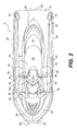
- FIG. 2 is a top view of the watercraft of FIG. 1;
- FIG. 3 is a front view of the watercraft of FIG. 1;
- FIG. 4 is a rear view of the watercraft of FIG. 1;
- FIG. 5 is a bottom view of the hull of the watercraft of FIG. 1;
- FIG. 6 illustrates an alternative stand-up type watercraft
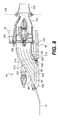
- FIG. 7 is a partial, cross-sectional side view of the stem of a watercraft showing a prior art jet propulsion system
- FIG. 8 is an enlarged, partial, cross-sectional side view of the stem of a watercraft showing a first embodiment of the jet propulsion system of the present invention
- FIG. 9 is a bottom view of a portion of the jet propulsion system of FIG. 8, showing the watercraft in a first condition
- FIG. 10 is a bottom view of a portion of the jet propulsion system of FIG. 8, showing the watercraft in a second condition;
- FIG. 11 is an enlarged, partial, cross-sectional side view of the stem of the watercraft showing another embodiment of the jet propulsion system of the present invention
- FIG. 12 is a bottom view of a portion of the jet propulsion system of FIG. 11;
- FIG. 13 is a bottom view of a portion of an alternative embodiment to the jet propulsion system illustrated in FIG. 11;
- FIG. 14 is a side view illustration of a further embodiment of a watercraft of the present invention, with a portion of the hull broken away to show part of the jet propulsion system;
- FIG. 15 is a rear view of the watercraft of FIG. 13, with a portion of the hull broken away to show part of the jet propulsion system;
- FIG. 16 is a bottom view of a portion of the jet propulsion system of FIG. 13;
- FIG. 17 is a side view illustration of another embodiment of the watercraft of the present invention, with a portion of the hull broken away to show part of the jet propulsion system;
- FIG. 18 is a bottom view of the watercraft illustrated in FIG. 17;
- FIG. 19 is a schematic side view in cross section of another embodiment of the watercraft of the present invention.
- FIG. 20 is a schematic side view in cross section of the embodiment of FIG. 19 shown in an open position.
- FIGS. 1 - 5 The general construction of a personal watercraft 10 in accordance with one embodiment of this invention is shown in FIGS. 1 - 5 .
- the watercraft 10 of FIG. 1 is made of two main parts, including a hull 12 and a deck 14 .
- the hull 12 buoyantly supports the watercraft 10 in the water.
- the deck 14 is designed to accommodate one rider and, in some watercraft, one or more passengers.
- the hull 12 and deck 14 are joined together in a sealing relationship at a seam 16 .
- the seam 16 comprises a bond line formed by an adhesive.
- other known joining methods could be used to sealingly engage the parts together, including but not limited to thermal fusion, molding, or fasteners, such as rivets or screws.
- a bumper 18 generally covers the seam 16 , which helps to prevent damage to the outer surface of the watercraft 10 when the watercraft 10 is docked, for example.
- the bumper 18 can extend around the bow, as shown, or around any portion or all of the seam 16 .
- the space between the hull 12 and the deck 14 forms a volume commonly referred to as the engine compartment 20 (shown in phantom). Shown schematically in FIG. 1, the engine compartment 20 accommodates an engine 22 , as well as a muffler, tuning pipe, gas tank, electrical system (battery, electronic control unit, etc.), air box, storage bins 24 , 26 , and other elements required or desirable in the watercraft 10 .
- the engine compartment 20 accommodates an engine 22 , as well as a muffler, tuning pipe, gas tank, electrical system (battery, electronic control unit, etc.), air box, storage bins 24 , 26 , and other elements required or desirable in the watercraft 10 .
- the deck 14 has a centrally positioned straddle-type seat 28 positioned on top of a pedestal 30 to accommodate a rider in a straddling position.
- the seat 28 may be sized to accommodate a single rider or sized for multiple riders.
- the seat 28 includes a first, front seat portion 32 and a rear, raised seat portion 34 that accommodates a passenger.
- the seat 28 is preferably made as a single, cushioned or padded unit. However, the seat 28 may be constructed as several separate parts that interfit with one another.
- the first and second seat portions 32 , 34 are preferably removably attached to the pedestal 30 by a hook and tongue assembly (not shown) at the front of each seat portion and by a latch assembly (not shown) at the rear of each seat portion, or by any other known attachment mechanism.
- the seat portions 32 , 34 can be individually, completely removed.
- One of the seat portions 32 , 34 covers an engine access opening (in this case above engine 22 ) defined by a top portion of the pedestal 30 to provide access to the engine 22 (FIG. 1).
- the other seat portion (in this case portion 34 ) can cover a removable storage box 26 (FIG. 1).
- a “glove compartment” or small storage box 36 may also be provided in front of the seat 28 .
- a grab handle 38 may be provided between the pedestal 30 and the rear of the seat 28 to provide a handle onto which a passenger may hold. This arrangement is particularly convenient for a passenger seated facing backwards for spotting a water skier, for example.
- a tow hook 40 Beneath the handle 38 , a tow hook 40 (FIG. 4) is mounted on the pedestal 30 .
- the tow hook 40 can be used for towing a skier or floatation device, such as an inflatable water toy.
- the watercraft 10 has a pair of generally upwardly extending walls located on either side of the watercraft 10 known as gunwales or gunnels 42 .
- the gunnels 42 help to prevent the entry of water in the footrests 46 of the watercraft 10 , provide lateral support for the rider's feet, and also provide buoyancy when turning the watercraft 10 , since personal watercraft roll slightly when turning.
- the gunnels 42 extend inwardly to act as heel rests 44 .
- Heel rests 44 allow a passenger riding the watercraft 10 facing towards the rear to spot a water-skier, for example, to place his or her heels on the heel rests 44 , thereby providing a more stable riding position. Heel rests 44 also could be formed as structures separate from the gunnels 42 .
- a pair of footrests 46 Located on both sides of the watercraft 10 , between the pedestal 30 and the gunnels 42 are a pair of footrests 46 .
- the footrests 46 are designed to accommodate a rider's feet in various riding positions. To this effect, the footrests 46 each have a forward portion 48 angled such that the front portion of the forward portion 48 (toward the bow of the watercraft 10 ) is higher, relative to a horizontal reference point, than the rear portion of the forward portion 48 .
- the remaining portions of the footrests 46 are generally horizontal. Of course, any contour conducive to a comfortable position for the rider could be used.
- the footrests 46 may be covered by carpeting 50 made of a rubber-type material, for example, to provide additional comfort and traction for the feet of the rider.
- a reboarding platform 52 is provided at the rear of the watercraft 10 on the deck 14 to allow the rider or a passenger to easily reboard the watercraft 10 from the water. Carpeting or some other suitable covering may cover the reboarding platform 52 .
- a retractable ladder (not shown) may be affixed to the transom 54 to facilitate boarding the watercraft 10 from the water.
- the watercraft 10 is provided with a hood 58 and a helm assembly 60 located forwardly of the seat 28 .
- a hinge (not shown) is attached between a forward portion of the hood 58 and the deck 14 to allow hood 58 to be opened to provide access to the front storage bin 24 (FIG. 1).
- a latch (not shown) located at a rearward portion of the hood 58 locks the hood 58 into a closed position. When in the closed position, the hood 58 prevents water from entering the front storage bin 24 .
- Rearview mirrors 62 are positioned on either side of the hood 58 to allow the rider to view objects behind the watercraft 10 .
- a hook 64 is located at the bow 56 of the watercraft 10 .
- the hook 64 is used to moor the watercraft 10 to a dock when the watercraft is not in use.
- the hook 64 also functions as a convenient location to attach a winch when loading the watercraft 10 onto a trailer, for instance.
- the hull 12 is provided with a combination of strakes 66 and chines 68 .
- a strake 66 is a protruding portion of the hull 12 .
- a chine 68 is the vertex formed where two surfaces of the hull 12 meet. The combination of strakes 66 and chines 68 provides the watercraft 10 with its riding and handling characteristics.
- Sponsons 70 are located on both sides of the hull 12 near the transom 54 .
- the sponsons 70 preferably have an arcuate undersurface that gives the watercraft 10 both lift while in motion and improved turning characteristics.
- the sponsons 70 are preferably fixed to the surface of the hull 12 and can be attached to the hull 12 by fasteners or be molded integrally therewith. It is contemplated that the position of the sponson 70 may be adjustable with respect to the hull 12 to change the handling characteristics of the watercraft 10 and accommodate different riding conditions.
- the helm assembly 60 is positioned forwardly of the seat 28 .
- the helm assembly 60 has a central helm portion 72 that may be padded and a pair of steering handles 74 , also referred to as a handlebar.
- One of the steering handles 74 is preferably provided with a throttle lever 76 , which allows the rider to control the speed of the watercraft 10 .
- a display area or cluster 78 is located forwardly of the helm assembly 60 .
- the display cluster 78 can be of any conventional display type, including LCD (liquid crystal displays), dials or LED (light emitting diodes).
- the central helm portion 72 may also have various buttons 80 , which could alternatively be in the form of levers or switches, that allow the rider to modify the display data or mode (speed, engine rpm, time, etc.) on the display cluster 78 .
- the central helm portion 72 also may be provided with one or more switches that change a condition of the watercraft 10 such as trim (the pitch of the watercraft) to modify the operational characteristics of the watercraft 10 .
- the helm assembly 60 may also be provided with a key receiving post 82 , preferably located near a center of the central helm portion 72 .
- the key receiving post 82 is adapted to receive a key (not shown), that starts the watercraft 10 .
- the key is typically attaches to a safety lanyard (not shown), which clips onto the operator's life vest or clothing.
- the key receiving post 82 may be placed in any suitable location on the watercraft 10 .
- the watercraft 10 is generally propelled by a jet propulsion system 84 , which includes a jet propulsion unit or jet pump.
- the jet propulsion system 84 is shown schematically in FIG. 1.
- the jet propulsion system 84 pressurizes water to create thrust.
- the water is first scooped from under the hull 12 through an inlet 86 , which preferably has a grate (not shown in detail in FIGS. 1 and 5).
- Water flows from the inlet 86 through a water intake ramp 88 .
- the top portion 90 of the water intake ramp 88 is formed by the hull 12 .
- a ride shoe (not shown in detail in FIGS. 1 and 5) forms the bottom portion 92 of the water intake ramp 88 .
- the intake ramp 88 may be a single piece or an insert to which the jet propulsion system 84 attaches. In such cases, the intake ramp 88 and the jet propulsion system 84 are attached as a unit in a recess in the bottom of hull 12 .
- the jet propulsion system 84 is located in a formation in the hull 12 referred to as the tunnel 94 (see FIG. 8).
- the tunnel 94 is defined at the front, sides, and top by the hull 12 and is open at the transom 54 .
- the bottom of the tunnel 94 is closed by the ride plate 96 .
- the ride plate 96 creates a surface on which the watercraft 10 rides or planes at high speeds.
- the jet propulsion system 84 includes a jet propulsion unit or jet pump 160 (seen in detail in FIG. 8, for example) made of two main parts: the impeller and the stator.
- the impeller is coupled to the engine 22 by one or more shafts 98 , such as a drive shaft and/or an impeller shaft.
- the one or more shafts 98 could be operatively connected to one another through a gearbox or clutch.
- the scope of the invention should not be limited to this type of jet pump arrangement.
- Other jet pump arrangements are also possible; for example, the jet pump 160 could have two contra-rotating impellers.
- the rotation of the impeller pressurizes the water, which then moves over the stator that is made of a plurality of fixed stator blades.
- the role of the stator blades is to decrease the rotational motion of the water so that almost all the energy given to the water is used for thrust, as opposed to swirling the water.
- Once the water leaves the jet pump 160 it goes through a venturi 100 . Since the venturi's exit diameter is smaller than its entrance diameter, the water is accelerated further, thereby providing more thrust.
- a steering nozzle 102 is pivotally attached to the venturi 100 so as to pivot about a vertical axis 104 .
- the steering nozzle 102 could also be supported at the exit of the tunnel 94 in other ways without a direct connection to the venturi 100 .
- the nozzle 102 may be replaced by a rudder that re-directs the pressurized water for steering.
- the steering nozzle 102 is operatively connected to the helm assembly 60 preferably via a push-pull cable (not shown) such that when the helm assembly 60 is turned, the steering nozzle 102 pivots about the vertical axis 104 . This movement redirects the water coming from the venturi 100 , so as to steer the watercraft 10 in the desired direction.
- the steering nozzle 102 may be gimbaled to allow it to move around a second horizontal pivot axis (not shown). The up and down movement of the steering nozzle 102 around the horizontal pivot axis is known as “trim” and controls the pitch of the watercraft 10 .
- a speed sensor 106 When the watercraft 10 is moving, its speed is measured by a speed sensor 106 (see FIG. 14) attached to the transom 54 of the watercraft 10 .
- the speed sensor 106 has a paddle wheel 108 that is turned by the flow of water. In operation, as the watercraft 10 goes faster, the paddle wheel 108 also turns faster.
- An electronic control unit (not shown) connected to the speed sensor 106 converts the rotational speed of the paddle wheel 108 to the speed of the watercraft 10 in kilometers or miles per hour, depending on the rider's preference.
- the speed sensor 106 may also be placed in the ride plate 96 or at any other suitable position. Other types of speed sensors, such as pitot tubes, and processing units could be used, as would be readily recognized by one of ordinary skill in the art.
- the watercraft 10 may be provided with the ability to move in a reverse direction.
- a reverse gate 110 seen in FIG. 4, is used.
- the reverse gate 110 is pivotally attached to the sidewalls of the tunnel 94 or directly on the venturi 100 or the steering nozzle 102 .
- the rider pulls on a reverse handle 112 (FIG. 1) operatively connected to the reverse gate 110 .
- the reverse gate 110 then pivots in front of the outlet of the steering nozzle 102 and redirects the water leaving the jet propulsion system 84 towards the front of the watercraft 10 , thereby thrusting the watercraft 10 rearwardly.
- the reverse handle 112 can be located in any convenient position near the operator, for example adjacent the seat 28 as shown or on the helm 60 .
- this invention can be embodied in a stand-up type personal watercraft 120 , as seen in FIG. 6.
- Stand-up watercraft 120 are often used in racing competitions and are known for high performance characteristics.
- such stand-up watercraft 120 have a lower center of gravity and a more concave hull 122 .
- the deck 124 may also have a lower profile.
- the seat is replaced with a standing platform 126 .
- the operator stands on the platform 126 between the gunnels 128 to operate the watercraft.
- the steering assembly 130 is configured as a pivoting handle pole 132 that tilts up from a pivot point 134 during operation, as shown in FIG. 6. At rest, the handle pole 132 folds downwardly against the deck 124 toward the standing platform 126 . Otherwise, the components and operation of the watercraft 120 are similar to watercraft 10 .
- FIG. 8 shows a first preferred embodiment of the jet propulsion system 84 of the present invention. As shown, the jet propulsion system 84 is disposed within the hull 12 , of which only a portion is shown in broken lines to reveal the details of the jet propulsion system 84 .
- the jet propulsion system 84 includes an inlet 86 in the hull 12 that leads to a water intake ramp 88 in the tunnel 94 .
- An inlet grate 148 can be provided at the inlet 86 .
- a pump support 150 is secured within the tunnel 94 .
- the water intake ramp 88 is defined by an interior wall 89 and a ramp portion 156 of the pump support 150 .
- the jet pump 160 is secured within the tunnel 94 to the pump support 150 .
- an elongate bag 202 containing fluid is disposed within the water intake ramp 88 .
- the bag 202 has a first end 204 disposed proximate to the inlet 86 and a second end 206 disposed proximate to the jet pump 160 .
- the bag 202 is attached to the starboard side of the water intake ramp interior wall 89 , as seen in FIG. 8.
- the bag 202 in this embodiment of the invention comprises a set of four generally parallel bags 212 , 214 , 216 , and 218 , which are shown being attached together in a side by side arrangement.
- the four bags 212 , 214 , 216 , and 218 could also be seen as four separate chambers of the elongate bag 202 .
- Each of the four bags 212 , 214 , 216 , and 218 preferably extends from the first end 204 to the second end 206 and contain fluid therein.
- the bag 202 need not include only four bags 212 , 214 , 216 , 218 to practice the present invention. To the contrary, any number of bags equal to or greater than one may be used to practice the present invention.
- the bags 212 , 214 , 216 , 218 need not be fluidically separated from one another.
- the bags 212 , 214 , 216 , 218 need not be fluidically connected to one another. It is contemplated that, where a plurality of bags are used, one or more of the bags may be connected to others of the bags. In other words, using the bag 202 as an example, bags 212 and 216 may be fluidically connected while bags 214 and 218 are fluidically distinct from one another and from bags 212 , 216 .
- the bag 202 forms a flexible barrier which separates water in the intake ramp 88 from the fluid in the bag 202 .
- the fluid within the bag 202 is disposed between water in the intake ramp 88 and a water intake ramp interior wall 89 .
- Fluid within the bag 202 is allowed to flow along its length, toward the water passage inlet 86 and away from the water passage inlet 86 .
- the flow of fluid within the bag 202 toward the inlet 86 constricts the inlet 86
- the flow of fluid within the bag 202 away from the inlet 86 dilates the inlet 86 .
- FIG. 9 shows the bottom side of the watercraft 10 .
- the inlet grate 148 has been removed so as not to conceal the details of the invention.
- the bag 202 which is disposed on the starboard side of the water intake ramp 88 , is accompanied by a second bag 220 disposed on the port side of the water intake ramp 88 . It is contemplated that the bags 202 , 220 can be used together or separately.
- the first end 204 of the bag 202 and a first end 222 of the bag 220 are shown in their respective positions within the water intake ramp 88 .
- bag 220 has an exterior surface 224 which is in contact with water in the water intake ramp 88 , and an interior surface 226 which is attached to the interior wall 89 of the water intake ramp 88 .
- FIG. 9 shows a first possible condition of the bags 202 , 220 , where the fluid is evenly distributed.
- FIG. 10 shows a second possible condition of the bags 202 , 220 , where the fluid is being pushed rearwardly toward the jet pump 160 .
- the bags 202 , 220 will assume whatever shape is optimal given the momentary dynamic and static forces acting thereon during operation of the watercraft 10 .
- Another aspect of this embodiment is providing a control mechanism to control the flow of fluid in the bags, either manually or automatically based on operating conditions of the watercraft 10 .
- a reservoir could be provided to allow fluid to flow into or out of the bags.
- control could be hydraulic, pneumatic, manual, or electronic, among others.
- fluids both liquids and gases
- Fluids such as gels having a substantial viscosity could also be used.
- a single elongate bag can be used or that elongate bags that do not have separated chambers can be used to practice the invention.
- the separate chambers could be disposed at any desired orientation, such a horizontal.
- any other position of the bag or bags within the water intake ramp 88 is considered to fall within the scope of the invention.
- bags could also be positioned at the top and bottom of the water intake ramp 88 .
- a bag may partially or wholly surround the inlet 86 to the water intake ramp 88 .
- the exact shape and positioning of one or more bags within the water intake ramp 88 is not critical to the practice of the present invention.
- FIG. 11 shows another preferred embodiment of the jet propulsion system 300 of the present invention.
- the jet propulsion system 300 is disposed within the hull 12 , of which only a portion is shown in broken lines to reveal the details of the jet propulsion system 300 .
- An adjustable ride plate 302 is used to modulate the amount of water entering through the inlet 86 into the water intake ramp 88 . The position of the ride plate 302 determines the size of inlet 86 .
- the entire ride plate 302 preferably moves forward and rearward with respect to the hull 12 .
- the ride plate 302 provides a rigid surface disposed for contact with a body of water while the watercraft 10 moves at high speeds.
- the ride plate 302 is movably mounted to a support plate 304 through the use of linear bearings (not shown) or other known structure that allows relative movement between two elements.
- the ride plate 302 has a forward end 303 , which is shown in a position immediately behind a rearward portion 149 of the inlet grate 148 .
- An actuator 306 actuates movement of the ride plate 302 in relation to the support plate 304 .
- the actuator 306 in this embodiment comprises an electric motor or other known electro-mechanic device such as a solenoid.
- the actuator 306 is mechanically connected to the ride plate through a rack 310 and pinion 312 gear system.
- a gear system is one of many ways that the actuator 306 could transmit movement to the ride plate 302 .
- Other systems include an actuator comprising a linear stepper motor that has a linear output shaft that pushes or pulls the ride plate 302 into a desired position. Hydraulic or pneumatic controls responsive to manual input or automatically responsive to operating conditions of the watercraft could also be used.
- the actuator 306 is preferably electrically connected to an ECU (shown schematically) or other known control unit through a known electrical connection such as wire 308 .
- the ECU is disposed to receive a condition of the watercraft and to transmit a signal to the actuator 306 in response to the condition received by the ECU.
- the condition of the watercraft 10 can be acceleration, as measured in a known manner through the monitoring of the throttle valve (not shown), changes in the speed as measured by the speed sensor 106 , or changes in the pressure within the water passage 95 as measured by a known pressure sensor 320 .
- the actuator changes the position of the ride plate 302 , thus changing the size of the inlet 86 .
- the adjustable ride plate 302 also conforms to the bottom surface of the hull 12 .
- the portions of the ride plate 302 are preferably disposed in substantially the same plane as the portions of the hull 12 immediately proximate thereto.
- the various portions of the ride plate 302 remain substantially disposed within the same plane throughout the movement of the ride plate 302 .
- the ride plate 302 is operatively moveable through a predetermined range from at least a first position where the ride plate 302 is entirely disposed behind the inlet 86 to a second position where the ride plate 302 partially covers the inlet 86 .
- the ride plate forward portion 303 which is shown in broken lines, is beneath and partially overlaps the inlet grate 148 .
- FIG. 12 shows ride plate 302 in the first and second positions, with the second position shown in broken lines.
- the ride plate 302 When the watercraft 10 is operated at a constant high speed, the ride plate 302 is maintained in the second position. In this second ride plate position, the ride plate 302 partially closes the inlet 86 . The amount of water necessary for the jet propulsion system 300 to generate sufficient thrust to maintain the constant speed is provided by the inlet 86 . However, when the watercraft 10 is accelerated, particularly from a low speed condition, the ride plate 302 is moved to the first position, thus reducing the water pressure drop in the inlet 86 . These improved flow conditions allow the jet pump 160 to operate at a higher efficiency level, thus generating a greater amount of thrust. Once the watercraft 10 reaches a higher speed, and a higher water pressure in the inlet 86 , the ride plate 302 is moved back into the second position.
- the ride plate 302 is not expected to have only first and second positions (e.g., an open inlet 86 and a partially-closed inlet 86 ). To the contrary, it is contemplated that the position of the ride plate 302 may vary between the first and second positions depending on the conditions input into the ECU.
- an electromechanical operating system is not required to practice the invention as would be appreciated by those skilled in the art, other actuating systems may be employed.
- the ride plate 302 may be biased into an opened position by a spring or other suitable biasing device. Movement of the ride plate 302 into a closed position (e.g., where the ride plate 302 partially covers the inlet 86 ) could then be accomplished fluidically. In other words, the increased pressure of the water in the water intake ramp 88 may be used to push the ride plate 302 in the closed position. With such a control system, when the watercraft 10 returns to a low-speed or accelerating condition , the biasing spring would then cause the ride plate to move into the partially-opened position.
- a hydraulic piston could be positioned between the ride plate 305 and the movable ride plate portion 303 to move the ride plate portion 303 during operation of the watercraft 10 . If a hydraulic piston is employed, the piston could be connected so that it utilizes the pressure of the water within the water intake ramp 88 for operation.
- FIG. 14 shows another preferred embodiment of the jet propulsion system 400 of the present invention.
- the jet propulsion system 400 is disposed within the hull 12 , a portion of which is broken away to reveal the details thereof.
- the primary water passage 95 is accompanied by at least a secondary water passage 410 which has an inlet 412 that is independent of the primary water passage inlet 86 .
- a valve 420 regulates the amount of water which may pass through the secondary water passage 410 .
- the secondary water passage 410 includes an outlet (elements 416 and 417 shown in FIG. 15) through which water in the secondary water passage 410 is discharged into the primary water passage 95 . Accordingly, the secondary water passage 410 is used to modulate the amount of water passing through the primary water passage 95 .
- FIG. 15 is a rear view with a portion of the transom 54 broken away to reveal the jet propulsion system 400 .
- the reverse bucket 110 has also been removed from this figure.
- the secondary water passage 410 is preferably accompanied by a tertiary water passage 414 , which, as shown in FIG. 14, are preferably connected.
- the secondary and tertiary water passages 410 , 414 are conduits in the form of an arch which straddle the primary water passage 95 .
- secondary and tertiary water passages 410 , 414 are shown, it would be apparent that only one of the two water passages 410 , 414 may be used. Alternatively, a greater amount of water passages can also be used.
- the secondary and tertiary water passages 410 , 414 can be a unitary conduit manufactured from metal, plastic or composite material, or an assembly of fittings.
- Outlets 416 , 417 are provided, which comprise passages through which water may flow from the secondary and tertiary water passages 410 , 414 into the primary water passage 95 .
- the outlets 416 , 417 can be openings in the water passages 410 , 414 .
- the outlets 416 , 417 can comprise fittings, valves, or other known devices or conduits through which liquids may be moved.
- the outlets 416 , 417 are disposed at an upper portion of the primary water passage 95 at a position upstream of the impeller within the jet propulsion unit 160 .
- the outlets 416 , 417 are also preferably disposed rearwardly, toward the stern, relative to the secondary water passage inlet 412 .
- the tertiary water passage 414 has an inlet 422 which, like the secondary water passage inlet 412 , is disposed laterally with respect to the primary water passage inlet 86 .
- the inlets 412 , 422 are formed directly in the hull 12 .
- the secondary water passage inlet 412 and tertiary water passage inlet 422 are both also preferably disposed immediately proximate to the primary water passage inlet 86 .
- the valve 420 which regulates the amount of water that may pass through the secondary water passage 410 , is disposed at the secondary water passage inlet 412 .
- a second valve 424 which regulates the amount of water that may pass through the tertiary water passage 420 , is disposed at the tertiary water passage inlet 422 .
- the valves 420 , 424 modulate the flow of water from the secondary and tertiary water passages 410 , 414 into the primary water passage 95 .
- the valves 420 , 424 are movable from at least a closed position where no water passes though the secondary and tertiary water passages 410 , 414 to an open position where water passes though the secondary and tertiary water passages 410 , 414 .
- An actuator 426 actuates movement of the valves 420 , 424 .
- the actuator 426 in this embodiment comprises an electric motor or other known electro-mechanic device such as a solenoid.
- the actuator 426 is mechanically connected to the valves 420 , 424 through known mechanical elements such as levers or gears through which the actuator 426 can transmit movement to the valves 420 , 424 .
- Other systems include an actuator comprising a linear stepper motor that has a linear output shaft that pushes or pulls the valves 420 , 424 into a desired position.
- other known actuators such as hydraulic or pneumatic, may be used.
- the actuator 426 is preferably electrically connected to an ECU (not shown) or other known control unit through a known electrical connection such as wire 427 .
- the ECU is disposed to receive a condition of the watercraft 10 and to transmit a signal to the actuator 426 in response to the condition received by the ECU.
- the condition of the watercraft 10 can be acceleration, as measured in a known manner through the monitoring of the throttle valve (not shown), changes in the speed as measured by the speed sensor 106 , or changes in the pressure within the water passage 95 as measured by a known pressure sensor 320 (shown previously in FIG. 11).
- the actuator changes the position of the valves 420 , 424 , thus changing the size of the inlets 412 , 422 .
- valves 420 , 424 When the watercraft 10 is operated at a high speed, the valves 420 , 424 are maintained in a closed or partially closed position. However, when the watercraft 10 is accelerated from a low speed or operates at a low speed, the valves 420 , 424 are opened to minimize the drop of water pressure in the inlet 86 . This minimizes the likeliness of cavitation to occur and allows the jet pump 160 to operate more efficiently. When the watercraft 10 reaches a high speed the valves 420 , 424 are moved back into the closed or partially closed position.
- FIGS. 17 and 18 illustrate one further embodiment of the present invention, jet propulsion system 500 .
- Jet propulsion system 500 is disposed within the hull, as shown in FIG. 17.
- Jet propulsion system 500 is similar to jet propulsion system 400 , except that the secondary water passage 502 is positioned forwardly of the primary water passage 95 .
- a valve 504 regulates the amount of water passing through the secondary water passage 502 .
- the secondary water passage 502 extends from a water inlet 506 to a connective opening 508 with the primary water passage 95 . As shown in FIG. 17, the secondary water passage 502 is separated from the primary water passage 95 by a wall 510 positioned at a forward end of the inlet 86 in longitudinal alignment with the primary water passage 95 .
- the valve 504 is essentially a gate-like structure that can be slid or positioned over the inlet 506 into the secondary water passage 502 .
- the valve 504 is opened progressively further to increase the total inlet area to minimize the drop of water pressure in the inlet 86 .
- the valve 504 closes the inlet 506 into the secondary water passage 502 (partially or wholly) to reduce the amount drag created by the water inlet 506 .
- the valve 504 may be controlled by an actuator 510 connected to an ECU via a wire (or wing) 512 .
- the actuator 510 may be electrically, electromagnetically, magnetically, hydraulically, or pneumatically controlled, among others.
- the location of the valve 504 is illustrated in FIG. 18.
- the secondary and tertiary water passages 410 , 414 could be used in combination with the secondary water passage 502 to further increase the total inlet cross-sectional area of the jet propulsion system, if desired.
- the secondary and tertiary water passages 410 , 414 , 502 are angled upwardly and rearwardly as illustrated in FIGS. 14 and 17 .
- the slanted arrangement of these water passages 410 , 414 , 502 assists in directing additional water through the jet propulsion systems 400 , 500 .
- the upward and rearward slant helps to scoop water up into water passages 410 , 414 , 502 .
- the design of the water passages 410 , 414 , 502 assists in improving the operation of the jet propulsion systems 400 , 500 .
- FIGS. 19 and 20 A similar embodiment is shown in FIGS. 19 and 20 in which the secondary water passage is angled upward and rearward.
- the water intake ramp 88 leads to the primary water passage 95 and a secondary water passage 550 is provided in the rearward portion of the intake ramp 88 against a rear wall 552 of the ramp 88 .
- the secondary water passage 550 is longitudinally aligned with the primary water passage 95 and has an inlet 554 and an outlet 556 that feeds into the primary water passage 95 .
- a pivotal arcuate plate 558 is mounted across the intake ramp 88 to either side of the hull 12 .
- the plate 558 is curved forming an inverted scoop.
- An actuating plate 560 is also pivotally mounted across the intake ramp 88 below the arcuate plate 558 .
- An actuator 562 is connected to the actuating plate 560 on either or both sides in the hull 12 in a slot (not shown).
- the actuator 562 may be a hydraulic piston as shown or any electrical or mechanical actuating mechanism, including a gear or cable, for example.
- the actuator 562 is connected to an ECU and may be controlled as described above in the same manner as in the other embodiments.
- the actuating plate 560 which functions as a valve, is lifted progressively, which opens inlet 554 and then lifts arcuate plate 558 , which also functions as a valve to control the volume of flow, to increase the total inlet area to minimize the drop of water pressure in the inlet 86 .
- the actuator 562 pushes the actuating plate 560 down to close the secondary water passage 550 (partially or wholly) to reduce the amount of drag created by water inlet 86 .
- the embodiments described herein are not mutually exclusive and can be used in combination. Additionally, as noted previously, this invention is not limited to PWC's.
- the jet propulsion systems disclosed herein may also be useful in small boats or other floatation devices other than those defined as personal watercrafts.
- the adjustable inlets disclosed herein may be used in any type of jet propulsion device.
Landscapes
- Physics & Mathematics (AREA)
- Fluid Mechanics (AREA)
- Chemical & Material Sciences (AREA)
- Engineering & Computer Science (AREA)
- Combustion & Propulsion (AREA)
- Mechanical Engineering (AREA)
- Ocean & Marine Engineering (AREA)
- Control Of Vehicle Engines Or Engines For Specific Uses (AREA)
Abstract
Description
- This application relies for priority on U.S. Provisional Patent Application Serial No. 60/371,497, filed on Apr. 11, 2002, entitled “WATERCRAFT HAVING A JET PROPULSION SYSTEM WITH IMPROVED EFFICIENCY.” The contents of that provisional patent application are incorporated herein by reference.
- 1. Field of the Invention
- This invention relates to jet powered watercraft, especially personal watercraft (“PWC”). More specifically, the invention concerns the jet propulsion system of the watercraft. In particular, the invention is directed to the construction of a water passage at a position upstream of a jet propulsion unit that modulates the amount of water allowed to pass through the water passage.
- 2. Description of Related Art
- Jet powered watercraft have become very popular in recent years for recreational use and for use as transportation in coastal communities. Jet-propelled watercraft offer high performance, improved acceleration and handling, and shallow-water operation. Accordingly, PWCs, which typically employ jet propulsion units, have become popular, especially in resort areas. As the use of PWCs has increased, a desire for improved performance, including greater operational efficiency, also has increased.
- Typically, jet powered watercraft, such as PWCs, have a jet propulsion system mounted within the hull that ingests water and expels the water at a high velocity from the stern to propel the watercraft. For directional control, a nozzle is generally provided at the outlet of the jet pump to direct the flow of water in a desired direction. In the conventional PWC, turning is achieved by redirecting the flow of water from the nozzle.
- In the typical arrangement for a jet propulsion unit, an engine output shaft is rotationally coupled to a drive shaft. The drive shaft extends into a water passage, which is defined by the hull of the watercraft partially below the water line. The water passage extends from a point forward of the rear of the watercraft to the rear of that watercraft. An impeller is attached to the drive shaft and is disposed within a pump housing portion of the water passage.
- FIG. 7 shows a prior art
jet propulsion system 600 disposed within thehull 612, of which only a portion is shown in broken lines. As shown, aninlet grate 642 is disposed at aninlet 686 to anintake ramp 688. Theinlet grate 642 prevents large rocks, weeds, and other debris from entering thewater intake ramp 688 and passing through thejet propulsion system 600. A pump support 650 or ride shoe forms thebottom portion 692 of thewater intake ramp 688. Thepump support 650 is coupled to thehull 612 within atunnel 694 through fasteners and/or adhesives (not shown). Thepump support 650 includes amain body portion 651 having avertical attachment surface 652, aforward attachment location 654 that is secured to aride plate 696, and aramp portion 656. A passage (not shown) extends through themain body portion 651 of thepump support 650. Theramp portion 656 forms thebottom portion 692 of thewater intake ramp 688. - From the
water intake ramp 688, water enters into ajet pump 660. Thejet pump 660 includes animpeller 670 and astator 680. The impeller includesblades 672 that extend from acenter portion 674 that is coupled to an engine by one ormore shafts 698, such as a drive shaft and/or an impeller shaft. The rotation of theimpeller 670 pressurizes the water, which then moves over thestator 680 that comprises a plurality offixed stator blades 682. The role of thestator blades 682 is to decrease the rotational motion of the water so that almost all the energy given to the water is used for thrust, as opposed to just swirling the water. As shown, theimpeller 670 and thestator 680 are both disposed within a jetpropulsion unit housing 690 or pump housing. However, it is also known to position thestator 680 at a position outside of thehousing 690 at a position downstream of thehousing 690. Thehousing 690 includes aperipheral wall 691 which defines a passage through which water passes. Aforward end 692 of the housingperipheral wall 691 is attached to thevertical attachment surface 654 or thepump support 650. Theforward end 692 of the housingperipheral wall 691 defines the inlet into thehousing 690. - Once the water leaves the
jet pump 660, it goes through aventuri 610. In this prior artjet propulsion unit 600, theventuri 610 is disposed at the rearward end of thehousing 690. Since the venturi's exit diameter is smaller than its entrance diameter, the water is accelerated further, thereby providing more thrust. As shown, theventuri 610 is integrated into thehousing 690 and comprises the outlet from thehousing 690. - A
steering nozzle 602 is pivotally attached to theventuri 610 so as to pivot about avertical axis 604. Thesteering nozzle 602 is operatively connected to a steering mechanism such as a steering handlebar (see, e.g., thesteering handlebar 74 shown in FIG. 1). Rotation of the steering handlebar causes thesteering nozzle 602 to pivot around thevertical axis 604, thereby directing the water discharge to result in a change in the steering direction of the watercraft. - A
water passage 695, through which water passes from left to right, is illustrated in FIG. 7. Moving from left to right in this illustration, which is upstream to downstream, thewater passage 695 is defined by theinlet 686, thewater intake ramp 688, the pump support passage 653, thejet pump 660, theventuri 610 and thesteering nozzle 602. - When the amount of water passing through the
jet propulsion system 600 is not optimized, it is possible that cavitation may occur as a result of operation of theimpeller 670. Cavitation occurs when an object, such as theimpeller 670, moves through a fluid, such as water, at a sufficient speed to cause the water to form pockets of vapor. In other words, theimpeller 670 can rotate so quickly that, at the tips of theimpeller blades 672, a sufficiently low pressure region may be created that the water will flash into vapor, creating small vapor bubbles. When the vapor bubbles collapse, the shock of the collapse can degrade the impeller blades 672 (especially at the tips of the blades 672) by “eating away” at or pitting theblades 672. In addition, cavitation also has the undesired effect of producing noise and vibration that also degrade the operational efficiency of the jet propulsion system 608. In addition, noise and vibration increases the stress and wear and tear on theimpeller 670 and components attached thereto. - In addition, when the watercraft is accelerating from a standing still or a low speed condition, the water drawn through the
inlet 686 by the action of thepump 660 experiences a drop of static pressure, which is a condition that promotes cavitation. This undesirable drop of pressure can be minimized by increasing the size of theinlet 686, thus optimizing the system for the acceleration mode. Conversely, as the speed of the craft increases, the static pressure in the inlet builds up which leads to a condition that minimizes the formation of cavitation on bubbles in the flow, thus improving the propulsive efficiency of thepump 660. However, when the craft is traveling at high speed, the inlet pressure typically reaches an unnecessarily high level, this being a result of the relatively large inlet size chosen to accommodate the constraints of the low speed acceleration mode. Since alarge inlet 686 cuts into the planing area of the hull thus increasing the drag, aninlet 686 optimized for acceleration from low speed will yield lower propulsive efficiency at high speed, while conversely aninlet 686 optimized for high speed will result in poor acceleration performance due to the occurrence of cavitation. - In view of the foregoing, a need has developed for a watercraft with a jet propulsion system that provides improved operational efficiency. Specifically, a need has developed for a watercraft design where the amount of water passing through the jet propulsion system can be modulated.
- Also, in view of the foregoing, especially in view of the current trend to increase the operational power of boats and PWCs, a need has developed for a watercraft where cavitation is minimized or eliminated altogether.
- These needs remain unaddressed by the prior art.
- One aspect of embodiments of this invention is to provide a watercraft with a jet propulsion system that operates with improved operational efficiency.
- Another aspect of the invention provides a watercraft with a jet propulsion system that minimizes or eliminates the occurrence of cavitation.
- A further aspect of the present invention provides a structure disposed at the inlet of the water passage through which the amount of water passing through the jet propulsion system can be modulated.
- In particular, this invention is directed to a watercraft with a hull having a bow and a stern. An engine is supported by the hull. A water passage is formed at least in part by the hull and has an inlet opening at a position forward of the stem of the hull, an interior, and an outlet at a position proximate to the stern of the hull. A jet propulsion unit is disposed in portion of the water passage. The jet propulsion unit is operatively connected to the engine. In one embodiment, a flexible barrier is disposed in the water passage upstream of the jet propulsion unit and a fluid is disposed on one side of the barrier such that the barrier separates the interior of the water passage from the fluid. The barrier is selectively movable with respect to the water passage.
- In another embodiment, this invention is directed to a watercraft having a hull with a bow and a stem, an engine supported by the hull, a water passage having an inlet opening at a position forward of the stem of the hull and an outlet at a position proximate to the stem of the hull. A jet propulsion unit is disposed in a portion of the water passage and is operatively connected to the engine. A ride plate is disposed on the hull proximate to the inlet. At least a portion of the ride plate is operatively moveable through a predetermined range from at least a first position where the ride plate portion is disposed behind the inlet and a second position where the ride plate portion partially covers the inlet. The position of the ride plate determines the size of the inlet.
- In a third embodiment, this invention is also directed to a watercraft having a hull with a bow and a stem, an engine supported by the hull, a primary water passage having an inlet opening at a position forward of the stern of the hull and an outlet at a position proximate to the stem of the hull. A jet propulsion unit is disposed in a portion of the primary water passage and is operatively connected to the engine. A secondary water passage longitudinally aligned with the primary water passage includes an inlet and an outlet through which water may flow from the secondary water passage into the primary water passage. A valve is disposed adjacent to the secondary water passage that modulates the flow of water from the secondary water passage into the primary water passage. The valve is movable from at least a first position and a second position. An actuator is operatively connected to the valve to move the valve between the first and second positions based on sensed conditions of the watercraft.
- In a fourth embodiment, this invention is also directed to a watercraft having a hull with a bow and a stem, an engine supported by the hull, a primary water passage having an inlet opening at a position forward of the stern of the hull and an outlet at a position proximate to the stem of the hull. A jet propulsion unit is disposed in a portion of the primary water passage and is operatively connected to the engine. A secondary water passage and a tertiary water passage are each disposed laterally adjacent to the primary water passage. The secondary water passage includes a secondary inlet and a secondary outlet through which water may flow from the secondary water passage into the primary water passage, and the tertiary water passage includes a tertiary inlet and a tertiary outlet through which water may flow from the tertiary water passage into the primary water passage. A valve is disposed adjacent to each of the secondary water passage and the tertiary water passage that modulates the flow of water from the secondary water passage and the tertiary water passage into the primary water passage. Each valve is movable between at least an open position and a closed position. An actuator is connected to the valves to move the valves between the open position and the closed position based on sensed conditions of the watercraft. A controller is operatively connected to the actuator that controls movement of the valves to progressively open when the watercraft accelerates and to progressively close when the watercraft is operated at a high speed.
- Preferably, the watercraft is a personal watercraft (PWC). The PWC can be a seated PWC or a stand-up PWC. Additionally, the watercraft could be a jet boat or a sport boat. The invention is not limited to watercraft and is applicable to various types of water-going vessels with jet propulsion units.
- These and other aspects of this invention will become apparent from the disclosure that follows and the figures appended hereto.
- An understanding of the various embodiments of the invention may be gained by virtue of the following figures, of which like elements in various figures will have common reference numbers, and wherein:
- FIG. 1 illustrates a side view of a watercraft in accordance with an embodiment of the invention;
- FIG. 2 is a top view of the watercraft of FIG. 1;
- FIG. 3 is a front view of the watercraft of FIG. 1;
- FIG. 4 is a rear view of the watercraft of FIG. 1;
- FIG. 5 is a bottom view of the hull of the watercraft of FIG. 1;
- FIG. 6 illustrates an alternative stand-up type watercraft;
- FIG. 7 is a partial, cross-sectional side view of the stem of a watercraft showing a prior art jet propulsion system;
- FIG. 8 is an enlarged, partial, cross-sectional side view of the stem of a watercraft showing a first embodiment of the jet propulsion system of the present invention;
- FIG. 9 is a bottom view of a portion of the jet propulsion system of FIG. 8, showing the watercraft in a first condition;
- FIG. 10 is a bottom view of a portion of the jet propulsion system of FIG. 8, showing the watercraft in a second condition;
- FIG. 11 is an enlarged, partial, cross-sectional side view of the stem of the watercraft showing another embodiment of the jet propulsion system of the present invention;
- FIG. 12 is a bottom view of a portion of the jet propulsion system of FIG. 11;
- FIG. 13 is a bottom view of a portion of an alternative embodiment to the jet propulsion system illustrated in FIG. 11;
- FIG. 14 is a side view illustration of a further embodiment of a watercraft of the present invention, with a portion of the hull broken away to show part of the jet propulsion system;
- FIG. 15 is a rear view of the watercraft of FIG. 13, with a portion of the hull broken away to show part of the jet propulsion system;
- FIG. 16 is a bottom view of a portion of the jet propulsion system of FIG. 13;
- FIG. 17 is a side view illustration of another embodiment of the watercraft of the present invention, with a portion of the hull broken away to show part of the jet propulsion system;
- FIG. 18 is a bottom view of the watercraft illustrated in FIG. 17;
- FIG. 19 is a schematic side view in cross section of another embodiment of the watercraft of the present invention; and
- FIG. 20 is a schematic side view in cross section of the embodiment of FIG. 19 shown in an open position.
- While this invention is specifically directed to a PWC and the jet propulsion system that powers such a watercraft, the invention is not intended to be limited solely to a PWC. As would be appreciated by those skilled in the art, the invention also encompasses other types of watercraft, including boats of any kind having water jet propulsion systems (e.g., sport boats, pontoon boats, yachts, etc.)
- The general construction of a
personal watercraft 10 in accordance with one embodiment of this invention is shown in FIGS. 1-5. - The
watercraft 10 of FIG. 1 is made of two main parts, including ahull 12 and adeck 14. Thehull 12 buoyantly supports thewatercraft 10 in the water. Thedeck 14 is designed to accommodate one rider and, in some watercraft, one or more passengers. Thehull 12 anddeck 14 are joined together in a sealing relationship at aseam 16. Preferably, theseam 16 comprises a bond line formed by an adhesive. Of course, other known joining methods could be used to sealingly engage the parts together, including but not limited to thermal fusion, molding, or fasteners, such as rivets or screws. Abumper 18 generally covers theseam 16, which helps to prevent damage to the outer surface of thewatercraft 10 when thewatercraft 10 is docked, for example. Thebumper 18 can extend around the bow, as shown, or around any portion or all of theseam 16. - The space between the
hull 12 and thedeck 14 forms a volume commonly referred to as the engine compartment 20 (shown in phantom). Shown schematically in FIG. 1, theengine compartment 20 accommodates anengine 22, as well as a muffler, tuning pipe, gas tank, electrical system (battery, electronic control unit, etc.), air box,storage bins watercraft 10. - As seen in FIGS. 1 and 2, the
deck 14 has a centrally positioned straddle-type seat 28 positioned on top of apedestal 30 to accommodate a rider in a straddling position. Theseat 28 may be sized to accommodate a single rider or sized for multiple riders. For example, as seen in FIG. 2, theseat 28 includes a first,front seat portion 32 and a rear, raisedseat portion 34 that accommodates a passenger. - The
seat 28 is preferably made as a single, cushioned or padded unit. However, theseat 28 may be constructed as several separate parts that interfit with one another. The first andsecond seat portions pedestal 30 by a hook and tongue assembly (not shown) at the front of each seat portion and by a latch assembly (not shown) at the rear of each seat portion, or by any other known attachment mechanism. Preferably, theseat portions seat portions pedestal 30 to provide access to the engine 22 (FIG. 1). The other seat portion (in this case portion 34) can cover a removable storage box 26 (FIG. 1). A “glove compartment” orsmall storage box 36 may also be provided in front of theseat 28. - As seen in FIG. 4, a
grab handle 38 may be provided between thepedestal 30 and the rear of theseat 28 to provide a handle onto which a passenger may hold. This arrangement is particularly convenient for a passenger seated facing backwards for spotting a water skier, for example. Beneath thehandle 38, a tow hook 40 (FIG. 4) is mounted on thepedestal 30. Thetow hook 40 can be used for towing a skier or floatation device, such as an inflatable water toy. - As best seen in FIGS. 2 and 4 the
watercraft 10 has a pair of generally upwardly extending walls located on either side of thewatercraft 10 known as gunwales or gunnels 42. Thegunnels 42 help to prevent the entry of water in thefootrests 46 of thewatercraft 10, provide lateral support for the rider's feet, and also provide buoyancy when turning thewatercraft 10, since personal watercraft roll slightly when turning. Towards the rear of thewatercraft 10, thegunnels 42 extend inwardly to act as heel rests 44. Heel rests 44 allow a passenger riding thewatercraft 10 facing towards the rear to spot a water-skier, for example, to place his or her heels on the heel rests 44, thereby providing a more stable riding position. Heel rests 44 also could be formed as structures separate from the gunnels 42. - Located on both sides of the
watercraft 10, between thepedestal 30 and thegunnels 42 are a pair offootrests 46. Thefootrests 46 are designed to accommodate a rider's feet in various riding positions. To this effect, thefootrests 46 each have aforward portion 48 angled such that the front portion of the forward portion 48 (toward the bow of the watercraft 10) is higher, relative to a horizontal reference point, than the rear portion of theforward portion 48. The remaining portions of thefootrests 46 are generally horizontal. Of course, any contour conducive to a comfortable position for the rider could be used. Thefootrests 46 may be covered bycarpeting 50 made of a rubber-type material, for example, to provide additional comfort and traction for the feet of the rider. - A reboarding
platform 52 is provided at the rear of thewatercraft 10 on thedeck 14 to allow the rider or a passenger to easily reboard thewatercraft 10 from the water. Carpeting or some other suitable covering may cover thereboarding platform 52. A retractable ladder (not shown) may be affixed to thetransom 54 to facilitate boarding thewatercraft 10 from the water. - Referring to the
bow 56, as seen in FIGS. 2 and 3, thewatercraft 10 is provided with ahood 58 and ahelm assembly 60 located forwardly of theseat 28. A hinge (not shown) is attached between a forward portion of thehood 58 and thedeck 14 to allowhood 58 to be opened to provide access to the front storage bin 24 (FIG. 1). A latch (not shown) located at a rearward portion of thehood 58 locks thehood 58 into a closed position. When in the closed position, thehood 58 prevents water from entering thefront storage bin 24. Rearview mirrors 62 are positioned on either side of thehood 58 to allow the rider to view objects behind thewatercraft 10. - A
hook 64 is located at thebow 56 of thewatercraft 10. Thehook 64 is used to moor thewatercraft 10 to a dock when the watercraft is not in use. Thehook 64 also functions as a convenient location to attach a winch when loading thewatercraft 10 onto a trailer, for instance. - As best seen in FIGS. 3, 4, and 5, the
hull 12 is provided with a combination ofstrakes 66 and chines 68. Astrake 66 is a protruding portion of thehull 12. Achine 68 is the vertex formed where two surfaces of thehull 12 meet. The combination ofstrakes 66 and chines 68 provides thewatercraft 10 with its riding and handling characteristics. -
Sponsons 70 are located on both sides of thehull 12 near thetransom 54. Thesponsons 70 preferably have an arcuate undersurface that gives thewatercraft 10 both lift while in motion and improved turning characteristics. Thesponsons 70 are preferably fixed to the surface of thehull 12 and can be attached to thehull 12 by fasteners or be molded integrally therewith. It is contemplated that the position of thesponson 70 may be adjustable with respect to thehull 12 to change the handling characteristics of thewatercraft 10 and accommodate different riding conditions. - As best seen in FIGS. 3 and 4, the
helm assembly 60 is positioned forwardly of theseat 28. Thehelm assembly 60 has acentral helm portion 72 that may be padded and a pair of steering handles 74, also referred to as a handlebar. One of the steering handles 74 is preferably provided with athrottle lever 76, which allows the rider to control the speed of thewatercraft 10. - As seen in FIG. 2, a display area or
cluster 78 is located forwardly of thehelm assembly 60. Thedisplay cluster 78 can be of any conventional display type, including LCD (liquid crystal displays), dials or LED (light emitting diodes). Thecentral helm portion 72 may also havevarious buttons 80, which could alternatively be in the form of levers or switches, that allow the rider to modify the display data or mode (speed, engine rpm, time, etc.) on thedisplay cluster 78. Thecentral helm portion 72 also may be provided with one or more switches that change a condition of thewatercraft 10 such as trim (the pitch of the watercraft) to modify the operational characteristics of thewatercraft 10. - The
helm assembly 60 may also be provided with akey receiving post 82, preferably located near a center of thecentral helm portion 72. Thekey receiving post 82 is adapted to receive a key (not shown), that starts thewatercraft 10. As is known, the key is typically attaches to a safety lanyard (not shown), which clips onto the operator's life vest or clothing. It should be noted that thekey receiving post 82 may be placed in any suitable location on thewatercraft 10. - Returning to FIGS. 1 and 5, the
watercraft 10 is generally propelled by ajet propulsion system 84, which includes a jet propulsion unit or jet pump. Thejet propulsion system 84 is shown schematically in FIG. 1. As is known, thejet propulsion system 84 pressurizes water to create thrust. The water is first scooped from under thehull 12 through aninlet 86, which preferably has a grate (not shown in detail in FIGS. 1 and 5). Water flows from theinlet 86 through awater intake ramp 88. Thetop portion 90 of thewater intake ramp 88 is formed by thehull 12. A ride shoe (not shown in detail in FIGS. 1 and 5) forms thebottom portion 92 of thewater intake ramp 88. Alternatively, theintake ramp 88 may be a single piece or an insert to which thejet propulsion system 84 attaches. In such cases, theintake ramp 88 and thejet propulsion system 84 are attached as a unit in a recess in the bottom ofhull 12. - From the
intake ramp 88, water enters thejet propulsion system 84. Thejet propulsion system 84 is located in a formation in thehull 12 referred to as the tunnel 94 (see FIG. 8). Thetunnel 94 is defined at the front, sides, and top by thehull 12 and is open at thetransom 54. The bottom of thetunnel 94 is closed by theride plate 96. Theride plate 96 creates a surface on which thewatercraft 10 rides or planes at high speeds. - The
jet propulsion system 84 includes a jet propulsion unit or jet pump 160 (seen in detail in FIG. 8, for example) made of two main parts: the impeller and the stator. The impeller is coupled to theengine 22 by one ormore shafts 98, such as a drive shaft and/or an impeller shaft. Alternatively, the one ormore shafts 98 could be operatively connected to one another through a gearbox or clutch. The scope of the invention should not be limited to this type of jet pump arrangement. Other jet pump arrangements are also possible; for example, thejet pump 160 could have two contra-rotating impellers. - The rotation of the impeller pressurizes the water, which then moves over the stator that is made of a plurality of fixed stator blades. The role of the stator blades is to decrease the rotational motion of the water so that almost all the energy given to the water is used for thrust, as opposed to swirling the water. Once the water leaves the
jet pump 160, it goes through aventuri 100. Since the venturi's exit diameter is smaller than its entrance diameter, the water is accelerated further, thereby providing more thrust. A steeringnozzle 102 is pivotally attached to theventuri 100 so as to pivot about avertical axis 104. The steeringnozzle 102 could also be supported at the exit of thetunnel 94 in other ways without a direct connection to theventuri 100. Alternatively, thenozzle 102 may be replaced by a rudder that re-directs the pressurized water for steering. - The
steering nozzle 102 is operatively connected to thehelm assembly 60 preferably via a push-pull cable (not shown) such that when thehelm assembly 60 is turned, the steeringnozzle 102 pivots about thevertical axis 104. This movement redirects the water coming from theventuri 100, so as to steer thewatercraft 10 in the desired direction. Optionally, the steeringnozzle 102 may be gimbaled to allow it to move around a second horizontal pivot axis (not shown). The up and down movement of thesteering nozzle 102 around the horizontal pivot axis is known as “trim” and controls the pitch of thewatercraft 10. - When the
watercraft 10 is moving, its speed is measured by a speed sensor 106 (see FIG. 14) attached to thetransom 54 of thewatercraft 10. Thespeed sensor 106 has apaddle wheel 108 that is turned by the flow of water. In operation, as thewatercraft 10 goes faster, thepaddle wheel 108 also turns faster. An electronic control unit (not shown) connected to thespeed sensor 106 converts the rotational speed of thepaddle wheel 108 to the speed of thewatercraft 10 in kilometers or miles per hour, depending on the rider's preference. Thespeed sensor 106 may also be placed in theride plate 96 or at any other suitable position. Other types of speed sensors, such as pitot tubes, and processing units could be used, as would be readily recognized by one of ordinary skill in the art. - The
watercraft 10 may be provided with the ability to move in a reverse direction. With this option, areverse gate 110, seen in FIG. 4, is used. Thereverse gate 110 is pivotally attached to the sidewalls of thetunnel 94 or directly on theventuri 100 or thesteering nozzle 102. To cause thewatercraft 102 move in a reverse direction, the rider pulls on a reverse handle 112 (FIG. 1) operatively connected to thereverse gate 110. Thereverse gate 110 then pivots in front of the outlet of thesteering nozzle 102 and redirects the water leaving thejet propulsion system 84 towards the front of thewatercraft 10, thereby thrusting thewatercraft 10 rearwardly. The reverse handle 112 can be located in any convenient position near the operator, for example adjacent theseat 28 as shown or on thehelm 60. - Alternatively, this invention can be embodied in a stand-up type
personal watercraft 120, as seen in FIG. 6. Stand-upwatercraft 120 are often used in racing competitions and are known for high performance characteristics. Typically, such stand-upwatercraft 120 have a lower center of gravity and a more concave hull 122. Thedeck 124 may also have a lower profile. In thiswatercraft 120, the seat is replaced with a standingplatform 126. The operator stands on theplatform 126 between thegunnels 128 to operate the watercraft. Thesteering assembly 130 is configured as apivoting handle pole 132 that tilts up from apivot point 134 during operation, as shown in FIG. 6. At rest, thehandle pole 132 folds downwardly against thedeck 124 toward the standingplatform 126. Otherwise, the components and operation of thewatercraft 120 are similar towatercraft 10. - FIG. 8 shows a first preferred embodiment of the
jet propulsion system 84 of the present invention. As shown, thejet propulsion system 84 is disposed within thehull 12, of which only a portion is shown in broken lines to reveal the details of thejet propulsion system 84. - As is shown in FIG. 8, the
jet propulsion system 84 includes aninlet 86 in thehull 12 that leads to awater intake ramp 88 in thetunnel 94. Aninlet grate 148 can be provided at theinlet 86. Apump support 150 is secured within thetunnel 94. Thewater intake ramp 88 is defined by aninterior wall 89 and aramp portion 156 of thepump support 150. Thejet pump 160 is secured within thetunnel 94 to thepump support 150. - According to one aspect of this invention, to control the volume of water entering the
jet pump 160, anelongate bag 202 containing fluid is disposed within thewater intake ramp 88. Thebag 202 has afirst end 204 disposed proximate to theinlet 86 and asecond end 206 disposed proximate to thejet pump 160. Specifically, thebag 202 is attached to the starboard side of the water intake rampinterior wall 89, as seen in FIG. 8. Thebag 202 in this embodiment of the invention comprises a set of four generallyparallel bags bags elongate bag 202. Each of the fourbags first end 204 to thesecond end 206 and contain fluid therein. - As would be appreciated by those skilled in the art, the
bag 202 need not include only fourbags bags bags bag 202 as an example,bags bags bags - The
bag 202 forms a flexible barrier which separates water in theintake ramp 88 from the fluid in thebag 202. Specifically, the fluid within thebag 202 is disposed between water in theintake ramp 88 and a water intake rampinterior wall 89. Fluid within thebag 202 is allowed to flow along its length, toward thewater passage inlet 86 and away from thewater passage inlet 86. The flow of fluid within thebag 202 toward theinlet 86 constricts theinlet 86, and the flow of fluid within thebag 202 away from theinlet 86 dilates theinlet 86. - FIG. 9 shows the bottom side of the
watercraft 10. In this figure, theinlet grate 148 has been removed so as not to conceal the details of the invention. As is shown in this figure, thebag 202, which is disposed on the starboard side of thewater intake ramp 88, is accompanied by asecond bag 220 disposed on the port side of thewater intake ramp 88. It is contemplated that thebags first end 204 of thebag 202 and afirst end 222 of thebag 220 are shown in their respective positions within thewater intake ramp 88. FIG. 9 further shows that theelongate bag 202 has anexterior surface 208 which is in contact with water in thewater intake ramp 88, and aninterior surface 210 which is attached to theinterior wall 89 of thewater intake ramp 88, through the use of fasteners (not shown) or adhesives (not shown). Similarly,bag 220 has anexterior surface 224 which is in contact with water in thewater intake ramp 88, and aninterior surface 226 which is attached to theinterior wall 89 of thewater intake ramp 88. - FIG. 9 shows a first possible condition of the
bags - FIG. 10 shows a second possible condition of the
bags jet pump 160. - The
bags watercraft 10. - Another aspect of this embodiment is providing a control mechanism to control the flow of fluid in the bags, either manually or automatically based on operating conditions of the
watercraft 10. In that case, a reservoir could be provided to allow fluid to flow into or out of the bags. Such control could be hydraulic, pneumatic, manual, or electronic, among others. - As would be apparent to one skilled in the art, a variety of fluids (both liquids and gases) could be used within the
bags - In addition, while the foregoing description focuses on one embodiment having two
bags interior walls 89 at the sides of thewater intake ramp 88, any other position of the bag or bags within thewater intake ramp 88 is considered to fall within the scope of the invention. In particular, bags could also be positioned at the top and bottom of thewater intake ramp 88. In yet another alternative embodiment, a bag may partially or wholly surround theinlet 86 to thewater intake ramp 88. As would be appreciated by those skilled in the art, the exact shape and positioning of one or more bags within thewater intake ramp 88 is not critical to the practice of the present invention. - FIG. 11 shows another preferred embodiment of the
jet propulsion system 300 of the present invention. As shown, thejet propulsion system 300 is disposed within thehull 12, of which only a portion is shown in broken lines to reveal the details of thejet propulsion system 300. Anadjustable ride plate 302 is used to modulate the amount of water entering through theinlet 86 into thewater intake ramp 88. The position of theride plate 302 determines the size ofinlet 86. - Specifically, in this embodiment of the present invention, the
entire ride plate 302 preferably moves forward and rearward with respect to thehull 12. As was previously described, theride plate 302 provides a rigid surface disposed for contact with a body of water while thewatercraft 10 moves at high speeds. Theride plate 302 is movably mounted to asupport plate 304 through the use of linear bearings (not shown) or other known structure that allows relative movement between two elements. Theride plate 302 has aforward end 303, which is shown in a position immediately behind arearward portion 149 of theinlet grate 148. - An
actuator 306 actuates movement of theride plate 302 in relation to thesupport plate 304. Theactuator 306 in this embodiment comprises an electric motor or other known electro-mechanic device such as a solenoid. In the embodiment shown in FIG. 11, theactuator 306 is mechanically connected to the ride plate through arack 310 andpinion 312 gear system. As would be apparent to one skilled in the art, such a gear system is one of many ways that theactuator 306 could transmit movement to theride plate 302. Other systems include an actuator comprising a linear stepper motor that has a linear output shaft that pushes or pulls theride plate 302 into a desired position. Hydraulic or pneumatic controls responsive to manual input or automatically responsive to operating conditions of the watercraft could also be used. - The
actuator 306 is preferably electrically connected to an ECU (shown schematically) or other known control unit through a known electrical connection such aswire 308. The ECU is disposed to receive a condition of the watercraft and to transmit a signal to theactuator 306 in response to the condition received by the ECU. The condition of thewatercraft 10 can be acceleration, as measured in a known manner through the monitoring of the throttle valve (not shown), changes in the speed as measured by thespeed sensor 106, or changes in the pressure within thewater passage 95 as measured by a knownpressure sensor 320. Upon the receipt of the signal at theactuator 306, the actuator changes the position of theride plate 302, thus changing the size of theinlet 86. - As was previously shown in FIG. 4 with respect to the
ride plate 96, theadjustable ride plate 302 also conforms to the bottom surface of thehull 12. Specifically, the portions of theride plate 302 are preferably disposed in substantially the same plane as the portions of thehull 12 immediately proximate thereto. The various portions of theride plate 302 remain substantially disposed within the same plane throughout the movement of theride plate 302. - The
ride plate 302 is operatively moveable through a predetermined range from at least a first position where theride plate 302 is entirely disposed behind theinlet 86 to a second position where theride plate 302 partially covers theinlet 86. As is shown in FIG. 11, when theride plate 302 is in the second position, the ride plateforward portion 303, which is shown in broken lines, is beneath and partially overlaps theinlet grate 148. FIG. 12 shows rideplate 302 in the first and second positions, with the second position shown in broken lines. - When the
watercraft 10 is operated at a constant high speed, theride plate 302 is maintained in the second position. In this second ride plate position, theride plate 302 partially closes theinlet 86. The amount of water necessary for thejet propulsion system 300 to generate sufficient thrust to maintain the constant speed is provided by theinlet 86. However, when thewatercraft 10 is accelerated, particularly from a low speed condition, theride plate 302 is moved to the first position, thus reducing the water pressure drop in theinlet 86. These improved flow conditions allow thejet pump 160 to operate at a higher efficiency level, thus generating a greater amount of thrust. Once thewatercraft 10 reaches a higher speed, and a higher water pressure in theinlet 86, theride plate 302 is moved back into the second position. - It should be noted that the
ride plate 302 is not expected to have only first and second positions (e.g., anopen inlet 86 and a partially-closed inlet 86). To the contrary, it is contemplated that the position of theride plate 302 may vary between the first and second positions depending on the conditions input into the ECU. - In addition, while the combination of an ECU and an
actuator 306 is contemplated in one embodiment of the invention, an electromechanical operating system is not required to practice the invention as would be appreciated by those skilled in the art, other actuating systems may be employed. - For example, it is contemplated that the
ride plate 302 may be biased into an opened position by a spring or other suitable biasing device. Movement of theride plate 302 into a closed position (e.g., where theride plate 302 partially covers the inlet 86) could then be accomplished fluidically. In other words, the increased pressure of the water in thewater intake ramp 88 may be used to push theride plate 302 in the closed position. With such a control system, when thewatercraft 10 returns to a low-speed or accelerating condition , the biasing spring would then cause the ride plate to move into the partially-opened position. - In yet another embodiment, as illustrated in FIG. 13, it is contemplated that only a
portion 303 of theride plate 305 will move to partially close the inlet opening 86 during a steady state operation. In this embodiment, theride plate 305 remains fixed in its position on thehull 12 of thewatercraft 10. As a result, the operational characteristics of thewatercraft 10 will remain more constant, despite the changing position of theride plate portion 303. As would be appreciated by those skilled in the art, any type of actuating device or system may be employed to move theride plate portion 303 during operation of thewatercraft 10, including those described above in connection with theride plate 305. - In this regard, it is contemplated that a hydraulic piston could be positioned between the
ride plate 305 and the movableride plate portion 303 to move theride plate portion 303 during operation of thewatercraft 10. If a hydraulic piston is employed, the piston could be connected so that it utilizes the pressure of the water within thewater intake ramp 88 for operation. - FIG. 14 shows another preferred embodiment of the
jet propulsion system 400 of the present invention. As shown, thejet propulsion system 400 is disposed within thehull 12, a portion of which is broken away to reveal the details thereof. In this embodiment, theprimary water passage 95 is accompanied by at least asecondary water passage 410 which has aninlet 412 that is independent of the primarywater passage inlet 86. Avalve 420 regulates the amount of water which may pass through thesecondary water passage 410. Thesecondary water passage 410 includes an outlet (elements secondary water passage 410 is discharged into theprimary water passage 95. Accordingly, thesecondary water passage 410 is used to modulate the amount of water passing through theprimary water passage 95. - FIG. 15 is a rear view with a portion of the transom 54 broken away to reveal the
jet propulsion system 400. Thereverse bucket 110 has also been removed from this figure. Thesecondary water passage 410 is preferably accompanied by atertiary water passage 414, which, as shown in FIG. 14, are preferably connected. Specifically, the secondary andtertiary water passages primary water passage 95. Although secondary andtertiary water passages water passages tertiary water passages -
Outlets tertiary water passages primary water passage 95. As would be appreciated by one skilled in the art, theoutlets water passages outlets outlets primary water passage 95 at a position upstream of the impeller within thejet propulsion unit 160. Theoutlets water passage inlet 412. - As shown in FIG. 16, the
tertiary water passage 414 has aninlet 422 which, like the secondarywater passage inlet 412, is disposed laterally with respect to the primarywater passage inlet 86. Preferably, theinlets hull 12. The secondarywater passage inlet 412 and tertiarywater passage inlet 422 are both also preferably disposed immediately proximate to the primarywater passage inlet 86. As is shown in FIGS. 14 and 16, thevalve 420, which regulates the amount of water that may pass through thesecondary water passage 410, is disposed at the secondarywater passage inlet 412. Asecond valve 424, which regulates the amount of water that may pass through thetertiary water passage 420, is disposed at the tertiarywater passage inlet 422. Thevalves tertiary water passages primary water passage 95. Thevalves tertiary water passages tertiary water passages - An
actuator 426 actuates movement of thevalves actuator 426 in this embodiment comprises an electric motor or other known electro-mechanic device such as a solenoid. Theactuator 426 is mechanically connected to thevalves actuator 426 can transmit movement to thevalves valves - The
actuator 426 is preferably electrically connected to an ECU (not shown) or other known control unit through a known electrical connection such aswire 427. The ECU is disposed to receive a condition of thewatercraft 10 and to transmit a signal to theactuator 426 in response to the condition received by the ECU. The condition of thewatercraft 10 can be acceleration, as measured in a known manner through the monitoring of the throttle valve (not shown), changes in the speed as measured by thespeed sensor 106, or changes in the pressure within thewater passage 95 as measured by a known pressure sensor 320 (shown previously in FIG. 11). Upon the receipt of the signal at theactuator 426, the actuator changes the position of thevalves inlets - When the
watercraft 10 is operated at a high speed, thevalves watercraft 10 is accelerated from a low speed or operates at a low speed, thevalves inlet 86. This minimizes the likeliness of cavitation to occur and allows thejet pump 160 to operate more efficiently. When thewatercraft 10 reaches a high speed thevalves - FIGS. 17 and 18 illustrate one further embodiment of the present invention,
jet propulsion system 500.Jet propulsion system 500 is disposed within the hull, as shown in FIG. 17.Jet propulsion system 500 is similar tojet propulsion system 400, except that thesecondary water passage 502 is positioned forwardly of theprimary water passage 95. Avalve 504 regulates the amount of water passing through thesecondary water passage 502. - The
secondary water passage 502 extends from awater inlet 506 to aconnective opening 508 with theprimary water passage 95. As shown in FIG. 17, thesecondary water passage 502 is separated from theprimary water passage 95 by awall 510 positioned at a forward end of theinlet 86 in longitudinal alignment with theprimary water passage 95. - As in the previous embodiment, the
valve 504 is essentially a gate-like structure that can be slid or positioned over theinlet 506 into thesecondary water passage 502. As thewatercraft 10 accelerates from a low speed condition, thevalve 504 is opened progressively further to increase the total inlet area to minimize the drop of water pressure in theinlet 86. When thewatercraft 10 is moving at a high velocity, thevalve 504 closes theinlet 506 into the secondary water passage 502 (partially or wholly) to reduce the amount drag created by thewater inlet 506. - As in the previous embodiment, the
valve 504 may be controlled by anactuator 510 connected to an ECU via a wire (or wing) 512. Theactuator 510 may be electrically, electromagnetically, magnetically, hydraulically, or pneumatically controlled, among others. The location of thevalve 504 is illustrated in FIG. 18. - As would be appreciated by those skilled in the art, the secondary and
tertiary water passages secondary water passage 502 to further increase the total inlet cross-sectional area of the jet propulsion system, if desired. - In both of the
jet propulsion systems tertiary water passages water passages jet propulsion systems water passages water passages jet propulsion systems - A similar embodiment is shown in FIGS. 19 and 20 in which the secondary water passage is angled upward and rearward. In this embodiment, the
water intake ramp 88 leads to theprimary water passage 95 and asecondary water passage 550 is provided in the rearward portion of theintake ramp 88 against arear wall 552 of theramp 88. Thesecondary water passage 550 is longitudinally aligned with theprimary water passage 95 and has aninlet 554 and anoutlet 556 that feeds into theprimary water passage 95. A pivotalarcuate plate 558 is mounted across theintake ramp 88 to either side of thehull 12. Theplate 558 is curved forming an inverted scoop. Anactuating plate 560 is also pivotally mounted across theintake ramp 88 below thearcuate plate 558. Anactuator 562 is connected to theactuating plate 560 on either or both sides in thehull 12 in a slot (not shown). Theactuator 562 may be a hydraulic piston as shown or any electrical or mechanical actuating mechanism, including a gear or cable, for example. - In operation, the
actuator 562 is connected to an ECU and may be controlled as described above in the same manner as in the other embodiments. As thewatercraft 10 accelerates from a low speed condition, theactuating plate 560, which functions as a valve, is lifted progressively, which opensinlet 554 and then liftsarcuate plate 558, which also functions as a valve to control the volume of flow, to increase the total inlet area to minimize the drop of water pressure in theinlet 86. When thewatercraft 10 is moving at a high velocity, theactuator 562 pushes theactuating plate 560 down to close the secondary water passage 550 (partially or wholly) to reduce the amount of drag created bywater inlet 86. - The embodiments described herein are not mutually exclusive and can be used in combination. Additionally, as noted previously, this invention is not limited to PWC's. For example, the jet propulsion systems disclosed herein may also be useful in small boats or other floatation devices other than those defined as personal watercrafts. The adjustable inlets disclosed herein may be used in any type of jet propulsion device.
- Although the above description contains specific examples of the present invention, these should not be construed as limiting the scope of the invention but as merely providing illustrations of some of the presently preferred embodiments of this invention. Thus, the scope of the invention should be determined by the appended claims and their legal equivalents rather than by the examples given.
Claims (31)
Priority Applications (1)
| Application Number | Priority Date | Filing Date | Title |
|---|---|---|---|
| US10/411,190 US6872105B2 (en) | 2002-04-11 | 2003-04-11 | Watercraft having a jet propulsion system with improved efficiency |
Applications Claiming Priority (2)
| Application Number | Priority Date | Filing Date | Title |
|---|---|---|---|
| US37149702P | 2002-04-11 | 2002-04-11 | |
| US10/411,190 US6872105B2 (en) | 2002-04-11 | 2003-04-11 | Watercraft having a jet propulsion system with improved efficiency |
Publications (2)
| Publication Number | Publication Date |
|---|---|
| US20030194924A1 true US20030194924A1 (en) | 2003-10-16 |
| US6872105B2 US6872105B2 (en) | 2005-03-29 |
Family
ID=28794407
Family Applications (1)
| Application Number | Title | Priority Date | Filing Date |
|---|---|---|---|
| US10/411,190 Expired - Lifetime US6872105B2 (en) | 2002-04-11 | 2003-04-11 | Watercraft having a jet propulsion system with improved efficiency |
Country Status (1)
| Country | Link |
|---|---|
| US (1) | US6872105B2 (en) |
Cited By (2)
| Publication number | Priority date | Publication date | Assignee | Title |
|---|---|---|---|---|
| US10118696B1 (en) | 2016-03-31 | 2018-11-06 | Steven M. Hoffberg | Steerable rotating projectile |
| US11712637B1 (en) | 2018-03-23 | 2023-08-01 | Steven M. Hoffberg | Steerable disk or ball |
Families Citing this family (4)
| Publication number | Priority date | Publication date | Assignee | Title |
|---|---|---|---|---|
| US20100041288A1 (en) * | 2008-08-12 | 2010-02-18 | Woodrow Woods | Submerged exhaust discharge for marine vessel |
| US20110053440A1 (en) * | 2009-08-31 | 2011-03-03 | Brp Us Inc. | Inlet grate for a water jet propulsion system |
| US10532797B2 (en) * | 2012-06-05 | 2020-01-14 | Steven John Derrah | Retractable drive for a powered surfboard |
| US9718521B2 (en) * | 2012-11-14 | 2017-08-01 | Steven John Derrah | Drive-N-glide surfboard (jet drive) |
Citations (13)
| Publication number | Priority date | Publication date | Assignee | Title |
|---|---|---|---|---|
| US3413948A (en) * | 1966-09-12 | 1968-12-03 | Chris Craft Ind Inc | Fluid pressure controlled planing and trim means for water craft |
| US3942463A (en) * | 1974-10-01 | 1976-03-09 | The United States Of America As Represented By The Secretary Of The Navy | Movable ramp inlet for water jet propelled ships |
| US4231315A (en) * | 1977-05-12 | 1980-11-04 | Kawasaki Jukogyo Kabushiki Kaisha | Water-jet propulsion unit for vessels |
| US4373919A (en) * | 1980-11-17 | 1983-02-15 | Rockwell International Corporation | Multi-passage variable diffuser inlet |
| US4449944A (en) * | 1979-01-02 | 1984-05-22 | Maritec Corporation | Variable inlet hydrojet boat drive |
| US4775341A (en) * | 1986-07-09 | 1988-10-04 | Wetco Industries | Foil system for jet propelled aquatic vehicle |
| US5199913A (en) * | 1991-05-16 | 1993-04-06 | Sanshin Kogyo Kabushiki Kaisha | Small, jet-propelled boat |
| US5324216A (en) * | 1991-05-24 | 1994-06-28 | Sanshin Kogyo Kabushiki Kaisha | Jet pump system for a water jet propelled boat |
| US5658176A (en) * | 1995-12-22 | 1997-08-19 | Jordan; Jeff P. | Marine jet propulsion system |
| US5910033A (en) * | 1995-05-12 | 1999-06-08 | Marine Technology Development Ltd. | Deflection mechanism for ship hulls |
| US5989083A (en) * | 1995-04-28 | 1999-11-23 | Ishigaki Company Limited | Water jet propulsion device for vessels |
| US6315624B1 (en) * | 2000-04-26 | 2001-11-13 | Bombardier Motor Corporation Of America | Exhaust probe |
| US6375523B1 (en) * | 1999-01-15 | 2002-04-23 | Eric Kyle Mathias | Personal watercraft (PWC) variable inlet/intake grate |
-
2003
- 2003-04-11 US US10/411,190 patent/US6872105B2/en not_active Expired - Lifetime
Patent Citations (14)
| Publication number | Priority date | Publication date | Assignee | Title |
|---|---|---|---|---|
| US3413948A (en) * | 1966-09-12 | 1968-12-03 | Chris Craft Ind Inc | Fluid pressure controlled planing and trim means for water craft |
| US3942463A (en) * | 1974-10-01 | 1976-03-09 | The United States Of America As Represented By The Secretary Of The Navy | Movable ramp inlet for water jet propelled ships |
| US4231315A (en) * | 1977-05-12 | 1980-11-04 | Kawasaki Jukogyo Kabushiki Kaisha | Water-jet propulsion unit for vessels |
| US4449944A (en) * | 1979-01-02 | 1984-05-22 | Maritec Corporation | Variable inlet hydrojet boat drive |
| US4373919A (en) * | 1980-11-17 | 1983-02-15 | Rockwell International Corporation | Multi-passage variable diffuser inlet |
| US4775341A (en) * | 1986-07-09 | 1988-10-04 | Wetco Industries | Foil system for jet propelled aquatic vehicle |
| US5199913A (en) * | 1991-05-16 | 1993-04-06 | Sanshin Kogyo Kabushiki Kaisha | Small, jet-propelled boat |
| US5324216A (en) * | 1991-05-24 | 1994-06-28 | Sanshin Kogyo Kabushiki Kaisha | Jet pump system for a water jet propelled boat |
| US5401198A (en) * | 1991-05-24 | 1995-03-28 | Sanshin Kogyo Kabushiki Kaisha | Jet pump system for a water jet propelled boat |
| US5989083A (en) * | 1995-04-28 | 1999-11-23 | Ishigaki Company Limited | Water jet propulsion device for vessels |
| US5910033A (en) * | 1995-05-12 | 1999-06-08 | Marine Technology Development Ltd. | Deflection mechanism for ship hulls |
| US5658176A (en) * | 1995-12-22 | 1997-08-19 | Jordan; Jeff P. | Marine jet propulsion system |
| US6375523B1 (en) * | 1999-01-15 | 2002-04-23 | Eric Kyle Mathias | Personal watercraft (PWC) variable inlet/intake grate |
| US6315624B1 (en) * | 2000-04-26 | 2001-11-13 | Bombardier Motor Corporation Of America | Exhaust probe |
Cited By (4)
| Publication number | Priority date | Publication date | Assignee | Title |
|---|---|---|---|---|
| US10118696B1 (en) | 2016-03-31 | 2018-11-06 | Steven M. Hoffberg | Steerable rotating projectile |
| US11230375B1 (en) | 2016-03-31 | 2022-01-25 | Steven M. Hoffberg | Steerable rotating projectile |
| US11712637B1 (en) | 2018-03-23 | 2023-08-01 | Steven M. Hoffberg | Steerable disk or ball |
| US12528027B1 (en) | 2018-03-23 | 2026-01-20 | Steven M. Hoffberg | Steerable rotating projectile |
Also Published As
| Publication number | Publication date |
|---|---|
| US6872105B2 (en) | 2005-03-29 |
Similar Documents
| Publication | Publication Date | Title |
|---|---|---|
| US8905800B2 (en) | Inlet grate for a water jet propulsion system | |
| US7841915B2 (en) | Jet propulsion trim and reverse system | |
| US8177594B2 (en) | Watercraft reverse gate operation | |
| US7708609B2 (en) | Watercraft reverse gate operation | |
| US8202136B2 (en) | Watercraft with steer-responsive reverse gate | |
| US7674144B2 (en) | Reverse gate for jet propelled watercraft | |
| US10864972B2 (en) | Trim system for a watercraft and method for controlling a trim of a watercraft | |
| US10919608B1 (en) | Jet propulsion system for a watercraft | |
| US9248895B1 (en) | Actuator for a gate of a watercraft jet propulsion system | |
| US20140373769A1 (en) | Watercraft hull | |
| US6892666B1 (en) | Watercraft suspension | |
| US4781141A (en) | Personal water craft with improved hull design | |
| US7901259B2 (en) | Method of indicating a deceleration of a watercraft | |
| US6675730B2 (en) | Personal watercraft having off-power steering system | |
| US8393287B2 (en) | Sponsons for a watercraft | |
| US6796858B2 (en) | Stator vane and impeller-drive shaft arrangements and personal watercraft employing the same | |
| US6872105B2 (en) | Watercraft having a jet propulsion system with improved efficiency | |
| US6422168B1 (en) | Sporting water vehicle | |
| US20120178318A1 (en) | Inlet Grate Cleaning System for a Water Jet Propulsion System | |
| US7958838B1 (en) | Watercraft hull | |
| JP4421320B2 (en) | Water jet propulsion type personal watercraft | |
| US7753746B1 (en) | Dual steering nozzle marine jet propulsion system | |
| US20030049978A1 (en) | Watercraft having a jet propulsion system that generates improved thrust | |
| CA2396479A1 (en) | Personal watercraft having off-power steering system | |
| US8075355B2 (en) | Marine jet propulsion steering system |
Legal Events
| Date | Code | Title | Description |
|---|---|---|---|
| AS | Assignment |
Owner name: BOMBARDIER MOTOR CORPORATION OF AMERICA, FLORIDA Free format text: ASSIGNMENT OF ASSIGNORS INTEREST;ASSIGNORS:DUSABLON, PATRICE;PESANT, GILES;MARATHE, BHASKAR;REEL/FRAME:013954/0310 Effective date: 20030411 |
|
| AS | Assignment |
Owner name: BOMBARDIER RECREATIONAL PRODUCTS INC., CANADA Free format text: ASSIGNMENT OF ASSIGNORS INTEREST;ASSIGNOR:BOMBARDIER MOTOR CORPORATION OF AMERICA;REEL/FRAME:014546/0480 Effective date: 20031218 |
|
| STCF | Information on status: patent grant |
Free format text: PATENTED CASE |
|
| AS | Assignment |
Owner name: BRP US INC., WISCONSIN Free format text: ASSIGNMENT OF ASSIGNORS INTEREST;ASSIGNOR:BOMBARDIER RECREATIONAL PRODUCTS INC.;REEL/FRAME:016059/0808 Effective date: 20050131 |
|
| AS | Assignment |
Owner name: BANK OF MONTREAL, AS ADMINISTRATIVE AGENT, CANADA Free format text: SECURITY AGREEMENT;ASSIGNOR:BRP US INC.;REEL/FRAME:018350/0269 Effective date: 20060628 |
|
| FEPP | Fee payment procedure |
Free format text: PAYOR NUMBER ASSIGNED (ORIGINAL EVENT CODE: ASPN); ENTITY STATUS OF PATENT OWNER: LARGE ENTITY |
|
| FPAY | Fee payment |
Year of fee payment: 4 |
|
| FPAY | Fee payment |
Year of fee payment: 8 |
|
| FPAY | Fee payment |
Year of fee payment: 12 |
|
| AS | Assignment |
Owner name: BANK OF MONTREAL, AS ADMINISTRATIVE AGENT, CANADA Free format text: SECURITY AGREEMENT (REVOLVER);ASSIGNOR:BRP US INC.;REEL/FRAME:047221/0082 Effective date: 20180929 |
|
| AS | Assignment |
Owner name: BANK OF MONTREAL, AS ADMINISTRATIVE AGENT, CANADA Free format text: SECURITY AGREEMENT (TERM LOAN);ASSIGNOR:BRP US INC.;REEL/FRAME:047225/0271 Effective date: 20180929 |