US20030194915A1 - Connector - Google Patents
Connector Download PDFInfo
- Publication number
- US20030194915A1 US20030194915A1 US10/122,225 US12222502A US2003194915A1 US 20030194915 A1 US20030194915 A1 US 20030194915A1 US 12222502 A US12222502 A US 12222502A US 2003194915 A1 US2003194915 A1 US 2003194915A1
- Authority
- US
- United States
- Prior art keywords
- isolation
- plastic body
- insertion plate
- plates
- slots
- Prior art date
- Legal status (The legal status is an assumption and is not a legal conclusion. Google has not performed a legal analysis and makes no representation as to the accuracy of the status listed.)
- Granted
Links
- 238000003780 insertion Methods 0.000 claims abstract description 50
- 230000037431 insertion Effects 0.000 claims abstract description 50
- 238000002955 isolation Methods 0.000 claims abstract description 40
- 230000008054 signal transmission Effects 0.000 claims abstract description 15
- XEEYBQQBJWHFJM-UHFFFAOYSA-N Iron Chemical compound [Fe] XEEYBQQBJWHFJM-UHFFFAOYSA-N 0.000 claims abstract description 14
- 229910052742 iron Inorganic materials 0.000 claims abstract description 7
- 230000002452 interceptive effect Effects 0.000 claims 1
- 238000007789 sealing Methods 0.000 abstract description 5
- 230000005611 electricity Effects 0.000 description 4
- 230000003068 static effect Effects 0.000 description 4
- 229910000831 Steel Inorganic materials 0.000 description 2
- 230000005540 biological transmission Effects 0.000 description 2
- 230000005855 radiation Effects 0.000 description 2
- 239000010959 steel Substances 0.000 description 2
- 238000005516 engineering process Methods 0.000 description 1
- 239000002184 metal Substances 0.000 description 1
- 229910052751 metal Inorganic materials 0.000 description 1
- 238000012986 modification Methods 0.000 description 1
- 230000004048 modification Effects 0.000 description 1
- 239000013307 optical fiber Substances 0.000 description 1
- 230000002093 peripheral effect Effects 0.000 description 1
- 238000005476 soldering Methods 0.000 description 1
Images


Classifications
-
- H—ELECTRICITY
- H01—ELECTRIC ELEMENTS
- H01R—ELECTRICALLY-CONDUCTIVE CONNECTIONS; STRUCTURAL ASSOCIATIONS OF A PLURALITY OF MUTUALLY-INSULATED ELECTRICAL CONNECTING ELEMENTS; COUPLING DEVICES; CURRENT COLLECTORS
- H01R13/00—Details of coupling devices of the kinds covered by groups H01R12/70 or H01R24/00 - H01R33/00
- H01R13/648—Protective earth or shield arrangements on coupling devices, e.g. anti-static shielding
- H01R13/658—High frequency shielding arrangements, e.g. against EMI [Electro-Magnetic Interference] or EMP [Electro-Magnetic Pulse]
- H01R13/6581—Shield structure
- H01R13/6585—Shielding material individually surrounding or interposed between mutually spaced contacts
- H01R13/6589—Shielding material individually surrounding or interposed between mutually spaced contacts with wires separated by conductive housing parts
-
- H—ELECTRICITY
- H01—ELECTRIC ELEMENTS
- H01R—ELECTRICALLY-CONDUCTIVE CONNECTIONS; STRUCTURAL ASSOCIATIONS OF A PLURALITY OF MUTUALLY-INSULATED ELECTRICAL CONNECTING ELEMENTS; COUPLING DEVICES; CURRENT COLLECTORS
- H01R13/00—Details of coupling devices of the kinds covered by groups H01R12/70 or H01R24/00 - H01R33/00
- H01R13/648—Protective earth or shield arrangements on coupling devices, e.g. anti-static shielding
- H01R13/658—High frequency shielding arrangements, e.g. against EMI [Electro-Magnetic Interference] or EMP [Electro-Magnetic Pulse]
- H01R13/6581—Shield structure
- H01R13/6585—Shielding material individually surrounding or interposed between mutually spaced contacts
-
- H—ELECTRICITY
- H01—ELECTRIC ELEMENTS
- H01R—ELECTRICALLY-CONDUCTIVE CONNECTIONS; STRUCTURAL ASSOCIATIONS OF A PLURALITY OF MUTUALLY-INSULATED ELECTRICAL CONNECTING ELEMENTS; COUPLING DEVICES; CURRENT COLLECTORS
- H01R2201/00—Connectors or connections adapted for particular applications
- H01R2201/06—Connectors or connections adapted for particular applications for computer periphery
-
- Y—GENERAL TAGGING OF NEW TECHNOLOGICAL DEVELOPMENTS; GENERAL TAGGING OF CROSS-SECTIONAL TECHNOLOGIES SPANNING OVER SEVERAL SECTIONS OF THE IPC; TECHNICAL SUBJECTS COVERED BY FORMER USPC CROSS-REFERENCE ART COLLECTIONS [XRACs] AND DIGESTS
- Y10—TECHNICAL SUBJECTS COVERED BY FORMER USPC
- Y10S—TECHNICAL SUBJECTS COVERED BY FORMER USPC CROSS-REFERENCE ART COLLECTIONS [XRACs] AND DIGESTS
- Y10S439/00—Electrical connectors
- Y10S439/942—Comblike retainer for conductor
Definitions
- the present invention relates to a connector, and more particularly to a connector having individually isolated terminals to eliminate mutual interference between the terminals during high-speed signal transmission and therefore enable faster and more stable transmission of signals.
- FIGS. 1 and 2 are exploded and partially assembled perspective views, respectively, of a conventional connector.
- the conventional connector includes an iron case 4 , a plastic body 1 , an insertion plate 2 , two hold-down plates 3 , an iron case 4 put onto an outer portion of front end of the plastic body 1 , and insertion plate 2 is connected to the rear end of the plastic body 1 .
- the plastic body 1 includes two rearward extended lateral walls 12 , inner surfaces of which are provided with two guide ways 13 each having a retaining hole 14 provided therein, such that the insertion plate 2 can be connected to a rear side of the plastic body 1 by sliding it into the guide ways 13 .
- the two lateral walls 12 have two vertically extended insertion slots 15 symmetrically provided at their inner surfaces.
- the insertion plate 2 is provided at two lateral sides with two retaining projections 22 for engaging with the retaining holes 14 in the guide ways 13 on the plastic body 1 , so as to hold the insertion plate 2 to a rear side of the plastic body 1 .
- the insertion plate 2 is also provided at upper and lower surfaces with a plurality of terminal slots 21 corresponding to the terminals 11 .
- rear ends of the terminals 11 are located in corresponding terminal slots 21 on the insertion plate 2 .
- Rear ends of the terminal slots 21 are spaced from one another with spacing ribs 23 .
- Middle portions of the spacing ribs 23 at both upper and lower sides of the insertion plate 2 are cut away to provide two transversely extended recesses 24 .
- two vertically extended slots 25 are provided at two lateral sides of the insertion plate 2 corresponding to the insertion slots 15 on the plastic body 1 .
- Each of the covering plates 3 is provided at middle points of two lateral sides with two projections 31 .
- the covering plates 3 are provided at a front part of one side facing the insertion plate 2 with a plurality of hold-down ribs 32 corresponding to and adapted to locate in the terminal slots 21 .
- the projections 31 may be vertically guided into the insertion slots 15 to connect the covering plates 3 to the plastic body 1 and to separately locate at upper and lower sides of the insertion plate 2 .
- Each of the intermediate cables 5 includes a plurality of conducting wire 51 that are arranged in a predetermined manner corresponding to the terminals 11 , and a transverse clamp plate 53 holding the previously arranged conducting wire 51 in place.
- a fixed length of front ends of the conducting wire 51 are extended from a front side of the clamp plate 53 to expose a fixed length of bare wires 52 .
- the pressed ribs 32 provided at the front part of the covering plates 3 are separately located in corresponding terminal slots 21 .
- rear parts of the covering plates 3 are integrally connected to tops of the spacing ribs 23
- the pressed ribs 32 at the front parts of the hold-down plates 3 are integrally connected at two lateral sides to two lateral sides of corresponding terminal slots 21 by way of high-frequency heat sealing, as shown in FIG. 3.
- the iron case 4 is then put onto the portion of front end of the plastic body 1 to complete the connector.
- FIG. 4 is a sectional view taken along line A-A′ of FIG. 3.
- the terminals might have static electricity surrounded them due to some external factors that affect the connector. Such static electricity forms an interference source in signal transmission.
- a primary object of the present invention is to provide a connector having individually isolated terminals, so that the terminals do not mutually interfere with one another during high-speed signal transmission, in order to enable faster and more stable transmission of signals.
- Another object of the present invention is to provide a connector that has reduced noise or crosstalk produced during high-speed transmission, so that signals can be more stably transmitted.
- a further object of the present invention is to provide a connector that eliminates static electricity possibly produced around terminals and therefore prevents the signal transmission from being interfered by static electricity.
- the connector of the present invention mainly includes a plastic body having a steel case put over a front end thereof, an insertion plate connected to a rear end of the plastic body, an intermediate cable including two rows of conducting wire separately set onto upper rear and lower rear sides of the insertion plate, and two covering plates separately covered onto upper and lower sides of the insertion plate to hold the conducting wire of the intermediate cable in place and then integrally connected to the insertion plate by way of high-frequency heat sealing.
- the plastic body, the insertion plate, and the covering plates are provided at predetermined positions with slots for receiving metal isolation plates therein, so that terminals on the plastic body are individually surrounded by the isolation plates to eliminate mutual interference and therefore enable stable transmission of signals at high speed.
- FIG. 1 is an exploded perspective view of a conventional connector
- FIG. 2 is a partially assembled perspective view of the connector of FIG. 1 before two hold-down plates are covered onto the connector;
- FIG. 3 is a fully assembled perspective view of the connector of FIG. 1;
- FIG. 4 is a sectional view taken along line A-A′ of FIG. 3;
- FIG. 5 is an exploded perspective view of a connector according to the present invention.
- FIG. 6 is an assembled perspective view of the connector of FIG. 5;
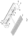
- FIG. 7 shows the first step of assembling the connector of the present invention by inserting terminals into terminal slots provided on a plastic body of the connector;
- FIG. 8 shows the second step of assembling the connector of the present invention by inserting isolation plates into isolation slots provided on the plastic body of the connector;
- FIG. 9 shows the third step of assembling the connector of the present invention by connecting an insertion plate to the plastic body of the connector
- FIG. 10 shows the fourth step of assembling the connector of the present invention by connecting an intermediate cable to the plastic body of the connector
- FIG. 11 shows the fifth step of assembling the connector of the present invention by covering two hold-down plates onto upper and lower sides of the plastic body of the connector to complete the assembling;
- FIG. 12 is a sectional view taken along line A-A of FIG. 6;
- FIG. 13 is a sectional view taken along line B-B of FIG. 6.
- FIGS. 5 and 6 are exploded and assembled perspective views, respectively, of a connector according to the present invention.
- the connector includes a plastic body 10 , an insertion plate 20 , two covering plates 30 , an iron case 40 , and intermediate cables 50 .
- the iron case 40 is connected to and covers an outer portion of front side of the plastic body 10
- the insertion plate 20 is assembled to a rear side of the plastic body 10 .
- the plastic body 10 is provided at the rear side with upper and lower rows of correspondingly arranged terminal slots 101 , into each of which a terminal 1011 is inserted, as shown in FIG. 7.
- a horizontal isolation slot 102 is provided between each upper terminal slot 101 and a corresponding lower terminal slot 101
- a vertical isolation slot 102 is provided between any two adjacent pairs of upper and lower terminal slots 101 , such that the horizontal and the vertical isolation slots 102 are transversely and sequentially arranged across the rear side of the plastic body 10 like a series of letters H.
- Each of the isolation slots 102 receives a front part of an isolation plate 1021 therein, as shown in FIG. 8.
- the plastic body 10 includes two rearward extended lateral walls 103 , inner surfaces of which are provided with horizontally extended guide slots 104 . And, two retaining holes 105 are separately formed in the guide slots 104 at predetermined positions for holding the insertion plate 20 to the rear side of the plastic body 10 , as shown in FIG. 9.
- the insertion plate 20 is provided at two lateral ends with two retaining projections 202 for engaging with the retaining holes 105 in the guide slots 104 of the plastic body 10 , and at upper and lower surfaces with a plurality of spacing ribs 201 . Any two adjacent spacing ribs 201 define a recess 203 between them for receiving a rear end of one corresponding terminal 1011 , a front end of which has been inserted into the terminal slot 101 on the plastic body 10 . Please refer to FIG. 9.
- the insertion plate 20 is provided at a front side facing toward the rear side of the plastic body 10 with a plurality of alternately arranged horizontal and vertical isolation slots 204 corresponding to the isolation plates 1021 inserted into the plastic body 10 , such that the alternate horizontal and the vertical isolation slots 204 look like a series of letters H.
- Each of the covering plates 30 is provided at front part of one side facing toward the upper or the lower surface of the insertion plate 20 with a plurality of raised pressed ribs 301 corresponding to the isolation ribs 201 of the insertion plate 20 , so that the covering plates 30 are covered onto upper and lower sides of the insertion plate 20 with the pressed ribs 301 abutting on tops of the isolation ribs 201 .
- the covering plate 30 is also provided at a front side with a plurality of isolation slots 302 , such that the isolation slots 302 are separately located between and below two adjacent pressed ribs 301 for receiving a row of flat isolation plates 303 therein.
- the intermediate cable 50 includes a plurality of conducting wire 501 that are previously arranged into two rows corresponding to the terminals 1011 in the upper and the lower row of terminal slots 101 , and then held in place with two horizontally extended clamp plates 503 . Front ends of the conducting wire 501 are projected from a front side of the clamp plates 503 to expose a fixed length of bare wires 502 for connecting to the terminals 1011 by way of soldering.
- FIG. 12 is a sectional view taken along line A-A of FIG. 6 showing the assembled connector of the present invention.
- FIG. 13 is a fragmentary sectional view taken along line B-B of FIG. 6.
- the isolation plates 1021 and 303 provide a plurality of isolation layers to surround the terminals 1011 , so that every terminal 1011 is individually isolated.
- the individually isolated terminals 1011 do not mutually interfere with one another during transmission of signals at extremely high speed, so that the signals are transmitted faster and more stably.
Landscapes
- Details Of Connecting Devices For Male And Female Coupling (AREA)
- Connector Housings Or Holding Contact Members (AREA)
Abstract
A connector mainly includes a plastic body having an iron case put over an outer portion of front end thereof, an insertion plate connected to a rear end of the plastic body, an intermediate cable including two rows of conducting wire separately set onto upper rear and lower rear sides of the insertion plate, and two covering plates separately covered onto upper and lower sides of the insertion plate to hold the conducting wire of the intermediate cable in place and then integrally connected to the insertion plate by way of high-frequency heat sealing. The plastic body, the insertion plate, and the covering plates are provided at predetermined positions with slots for receiving isolation plates therein, so that terminals inserted in the plastic body are individually surrounded by the isolation plates to eliminate mutual interference and therefore enable stable transmission of signals at high speed.
Description
- The present invention relates to a connector, and more particularly to a connector having individually isolated terminals to eliminate mutual interference between the terminals during high-speed signal transmission and therefore enable faster and more stable transmission of signals.
- With the increasingly developed technologies, computers have been designed to provide incredibly powerful functions. That is, the central processing unit (CPU) inside each computer has higher operation ability than ever. Meanwhile, the Internet has become so popular that upload and download at extremely high speed via wide-band optical fiber, asymmetric digital subscriber line (ADSL) and the like has been developed in response to user demands. Thus, peripheral Active/passive components for using the Internet must have matched high operating speed. A cable for transmitting signals between the CPU of a computer and the Active/passive components is therefore particularly important, and connectors at two ends of the cable are responsible for successful high-speed signal transmission.
- FIGS. 1 and 2 are exploded and partially assembled perspective views, respectively, of a conventional connector. As shown, the conventional connector includes an
iron case 4, aplastic body 1, aninsertion plate 2, two hold-down plates 3, aniron case 4 put onto an outer portion of front end of theplastic body 1, andinsertion plate 2 is connected to the rear end of theplastic body 1. - Two rows of staggered
terminals 11 are provided at upper and lower sides of theplastic body 1. Theplastic body 1 includes two rearward extendedlateral walls 12, inner surfaces of which are provided with twoguide ways 13 each having aretaining hole 14 provided therein, such that theinsertion plate 2 can be connected to a rear side of theplastic body 1 by sliding it into theguide ways 13. Moreover, the twolateral walls 12 have two vertically extendedinsertion slots 15 symmetrically provided at their inner surfaces. - The
insertion plate 2 is provided at two lateral sides with tworetaining projections 22 for engaging with the retainingholes 14 in theguide ways 13 on theplastic body 1, so as to hold theinsertion plate 2 to a rear side of theplastic body 1. Theinsertion plate 2 is also provided at upper and lower surfaces with a plurality ofterminal slots 21 corresponding to theterminals 11. When theinsertion plate 2 is connected to the rear side of theplastic body 1, rear ends of theterminals 11 are located incorresponding terminal slots 21 on theinsertion plate 2. Rear ends of theterminal slots 21 are spaced from one another withspacing ribs 23. Middle portions of thespacing ribs 23 at both upper and lower sides of theinsertion plate 2 are cut away to provide two transversely extendedrecesses 24. And, two vertically extendedslots 25 are provided at two lateral sides of theinsertion plate 2 corresponding to theinsertion slots 15 on theplastic body 1. - Each of the
covering plates 3 is provided at middle points of two lateral sides with twoprojections 31. Thecovering plates 3 are provided at a front part of one side facing theinsertion plate 2 with a plurality of hold-down ribs 32 corresponding to and adapted to locate in theterminal slots 21. Theprojections 31 may be vertically guided into theinsertion slots 15 to connect thecovering plates 3 to theplastic body 1 and to separately locate at upper and lower sides of theinsertion plate 2. - Each of the
intermediate cables 5 includes a plurality of conductingwire 51 that are arranged in a predetermined manner corresponding to theterminals 11, and atransverse clamp plate 53 holding the previously arranged conductingwire 51 in place. A fixed length of front ends of the conductingwire 51 are extended from a front side of theclamp plate 53 to expose a fixed length ofbare wires 52. - To assemble the above-described conventional connector, first connect the
insertion plate 2 to the rear side of theplastic body 1, and then set theclamp plates 53 of thecables 5 in therecesses 24 at upper and lower sides of theinsertion plate 2, as shown in FIG. 2, such that the conductingwire 51 are separately located in and between twoadjacent spacing ribs 23 with thebare wires 52 pressed against rear ends ofcorresponding terminals 11. Thereafter, the twocovering plates 3 are connected to theplastic body 1 to separately locate at upper and lower sides of theinsertion plate 2 by guiding theprojections 31 into theinsertion slots 15 to engage with theslots 25. After thecovering plates 3 are held in place, the pressedribs 32 provided at the front part of thecovering plates 3 are separately located incorresponding terminal slots 21. Finally, rear parts of thecovering plates 3 are integrally connected to tops of thespacing ribs 23, and the pressedribs 32 at the front parts of the hold-downplates 3 are integrally connected at two lateral sides to two lateral sides ofcorresponding terminal slots 21 by way of high-frequency heat sealing, as shown in FIG. 3. Theiron case 4 is then put onto the portion of front end of theplastic body 1 to complete the connector. - Please refer to FIG. 4 that is a sectional view taken along line A-A′ of FIG. 3. After the rear parts of the
covering plates 3 are integrally connected to the tops of thespacing ribs 23 and the pressedribs 32 at the front parts of thecovering plates 3 are integrally connected at two lateral sides to two lateral sides ofcorresponding terminal slots 21, thebare wires 52 are separately located inindividual terminal slots 21 to tightly contact with rear ends ofcorresponding terminals 11, such that short circuit at joints of thebare wires 52 and theterminals 11 can be eliminated. - The following disadvantages are found in the above-described conventional connector:
- 1. When signals are transmitted at high speed via the closely arranged terminals, electric energy on the terminals produces radiation to result in mutual interfere of the terminals with one another and accordingly slow and unstable signal transmission.
- 2. During high-speed transmission, electric energy on the connector produces radiation to form noise or crosstalk that interferes with other terminals to result in worse signal transmission.
- 3. The terminals might have static electricity surrounded them due to some external factors that affect the connector. Such static electricity forms an interference source in signal transmission.
- It is therefore desirable to develop an improved connector having individually isolated terminals to eliminate mutual interference of terminals with one another during high-speed signal transmission and enable faster and more stable transmission of signals.
- A primary object of the present invention is to provide a connector having individually isolated terminals, so that the terminals do not mutually interfere with one another during high-speed signal transmission, in order to enable faster and more stable transmission of signals.
- Another object of the present invention is to provide a connector that has reduced noise or crosstalk produced during high-speed transmission, so that signals can be more stably transmitted.
- A further object of the present invention is to provide a connector that eliminates static electricity possibly produced around terminals and therefore prevents the signal transmission from being interfered by static electricity.
- To achieve the above and other objects, the connector of the present invention mainly includes a plastic body having a steel case put over a front end thereof, an insertion plate connected to a rear end of the plastic body, an intermediate cable including two rows of conducting wire separately set onto upper rear and lower rear sides of the insertion plate, and two covering plates separately covered onto upper and lower sides of the insertion plate to hold the conducting wire of the intermediate cable in place and then integrally connected to the insertion plate by way of high-frequency heat sealing. The plastic body, the insertion plate, and the covering plates are provided at predetermined positions with slots for receiving metal isolation plates therein, so that terminals on the plastic body are individually surrounded by the isolation plates to eliminate mutual interference and therefore enable stable transmission of signals at high speed.
- The structure and the technical means adopted by the present invention to achieve the above and other objects can be best understood by referring to the following detailed description of the preferred embodiments and the accompanying drawings, wherein
- FIG. 1 is an exploded perspective view of a conventional connector;
- FIG. 2 is a partially assembled perspective view of the connector of FIG. 1 before two hold-down plates are covered onto the connector;
- FIG. 3 is a fully assembled perspective view of the connector of FIG. 1;
- FIG. 4 is a sectional view taken along line A-A′ of FIG. 3;
- FIG. 5 is an exploded perspective view of a connector according to the present invention;
- FIG. 6 is an assembled perspective view of the connector of FIG. 5;
- FIG. 7 shows the first step of assembling the connector of the present invention by inserting terminals into terminal slots provided on a plastic body of the connector;
- FIG. 8 shows the second step of assembling the connector of the present invention by inserting isolation plates into isolation slots provided on the plastic body of the connector;
- FIG. 9 shows the third step of assembling the connector of the present invention by connecting an insertion plate to the plastic body of the connector;
- FIG. 10 shows the fourth step of assembling the connector of the present invention by connecting an intermediate cable to the plastic body of the connector;
- FIG. 11 shows the fifth step of assembling the connector of the present invention by covering two hold-down plates onto upper and lower sides of the plastic body of the connector to complete the assembling;
- FIG. 12 is a sectional view taken along line A-A of FIG. 6; and
- FIG. 13 is a sectional view taken along line B-B of FIG. 6.
- Please refer to FIGS. 5 and 6 that are exploded and assembled perspective views, respectively, of a connector according to the present invention. As shown, the connector includes a
plastic body 10, aninsertion plate 20, twocovering plates 30, aniron case 40, andintermediate cables 50. Theiron case 40 is connected to and covers an outer portion of front side of theplastic body 10, and theinsertion plate 20 is assembled to a rear side of theplastic body 10. - The
plastic body 10 is provided at the rear side with upper and lower rows of correspondingly arrangedterminal slots 101, into each of which aterminal 1011 is inserted, as shown in FIG. 7. Ahorizontal isolation slot 102 is provided between each upperterminal slot 101 and a corresponding lowerterminal slot 101, and avertical isolation slot 102 is provided between any two adjacent pairs of upper and lowerterminal slots 101, such that the horizontal and thevertical isolation slots 102 are transversely and sequentially arranged across the rear side of theplastic body 10 like a series of letters H. Each of theisolation slots 102 receives a front part of anisolation plate 1021 therein, as shown in FIG. 8. Theplastic body 10 includes two rearward extendedlateral walls 103, inner surfaces of which are provided with horizontally extendedguide slots 104. And, two retainingholes 105 are separately formed in theguide slots 104 at predetermined positions for holding theinsertion plate 20 to the rear side of theplastic body 10, as shown in FIG. 9. - The
insertion plate 20 is provided at two lateral ends with two retainingprojections 202 for engaging with the retainingholes 105 in theguide slots 104 of theplastic body 10, and at upper and lower surfaces with a plurality of spacingribs 201. Any twoadjacent spacing ribs 201 define arecess 203 between them for receiving a rear end of one correspondingterminal 1011, a front end of which has been inserted into theterminal slot 101 on theplastic body 10. Please refer to FIG. 9. Theinsertion plate 20 is provided at a front side facing toward the rear side of theplastic body 10 with a plurality of alternately arranged horizontal andvertical isolation slots 204 corresponding to theisolation plates 1021 inserted into theplastic body 10, such that the alternate horizontal and thevertical isolation slots 204 look like a series of letters H. - Please refer to FIG. 11. Each of the covering
plates 30 is provided at front part of one side facing toward the upper or the lower surface of theinsertion plate 20 with a plurality of raised pressedribs 301 corresponding to theisolation ribs 201 of theinsertion plate 20, so that the coveringplates 30 are covered onto upper and lower sides of theinsertion plate 20 with the pressedribs 301 abutting on tops of theisolation ribs 201. The coveringplate 30 is also provided at a front side with a plurality ofisolation slots 302, such that theisolation slots 302 are separately located between and below two adjacentpressed ribs 301 for receiving a row offlat isolation plates 303 therein. After theintermediate cable 50 and theterminals 1011 are connected together, the pressedribs 301 of the coveringplates 30 are integrally connected to the tops of thespacing ribs 201 of theinsertion plate 20 by way of high-frequency heat sealing. - Please refer to FIG. 10. The
intermediate cable 50 includes a plurality ofconducting wire 501 that are previously arranged into two rows corresponding to theterminals 1011 in the upper and the lower row ofterminal slots 101, and then held in place with two horizontally extendedclamp plates 503. Front ends of theconducting wire 501 are projected from a front side of theclamp plates 503 to expose a fixed length ofbare wires 502 for connecting to theterminals 1011 by way of soldering. - To assemble the connector of the present invention, first slide the
insertion plate 20 into theplastic body 10 via theguide slots 104, and separately set the twoclamp plates 503 of theintermediate cable 50 onto upper and lower sides of theinsertion plate 20, so that everyconducting wire 501 is located in acorresponding recess 203 between twoadjacent spacing ribs 201, enabling thebare wire 502 of everyconducting wire 501 to be soldered to the rear end of the correspondingterminal 1011. Thereafter, cover the two coveringplates 30 onto upper and lower sides of theinsertion plate 20 with the pressedribs 301 abutted against thespacing ribs 201. Finally, connect the pressedribs 301 and thespacing ribs 201 together by way of high-frequency heat sealing, and put thesteel case 40 onto the front side of theplastic body 10 to complete the connector. FIG. 12 is a sectional view taken along line A-A of FIG. 6 showing the assembled connector of the present invention. - FIG. 13 is a fragmentary sectional view taken along line B-B of FIG. 6. As can be seen in FIG. 13, in the assembled connector, the
isolation plates terminals 1011, so that everyterminal 1011 is individually isolated. The individually isolatedterminals 1011 do not mutually interfere with one another during transmission of signals at extremely high speed, so that the signals are transmitted faster and more stably. - The present invention has been described with a preferred embodiment thereof and it is understood that many changes and modifications in the described embodiment can be carried out without departing from the scope and the spirit of the invention as defined by the appended claims.
Claims (4)
1. A connector, comprising a plastic body having an iron case put over an outer portion of front side thereof, an insertion plate connected to a rear side of said plastic body, the intermediate cables including two rows of conducting wire separately set onto upper rear and lower rear sides of said insertion plate, and two covering plates separately covered onto upper and lower sides of said insertion plate to hold said conducting wire of said intermediate cable in place;
said plastic body including a plurality of upper and lower terminal slots arranged in a predetermined manner for each receiving a terminal therein, and a plurality of horizontal and vertical isolation slots; each of said horizontal isolation slots being provided between one said upper terminal slot and a corresponding one of said lower terminal slot, and each of said vertical first isolation slot being provided between any two adjacent pairs of said upper and said lower terminal slots; said horizontal and vertical first isolation slots receiving front parts of a plurality of first isolation plates therein, and said two rows of conducting wire of said intermediate cable being conveniently positioned in rear openings of said first isolation plates;
said insertion plate being provided at surfaces with a plurality of spacing ribs, and a plurality of recesses defined between two said spacing ribs that are adjacent to each other to separately receive rear ends of said terminals therein, and said insertion plate being provided at a front side facing toward said rear side of said plastic body with a plurality of horizontal and vertical second isolation slots corresponding to said first isolating plates inserted in said plastic body, so as to engage with rear ends of said first isolation plates; and
each of said two covering plates being provided at a side with a plurality of third isolation slots corresponding to said open side of said first isolation plates on said plastic body, and at front part of one side facing toward said insertion plate with a plurality of pressed ribs corresponding to and adapted to integrally connect to tops of said spacing ribs on said insertion plate; and a row of connected second isolation plates being inserted into said third isolation slots provided on each of said covering plates, such that each said second isolation plate and a corresponding one of said first isolation plates together provide an isolation layer surrounding each said terminal located in said terminal slot;
whereby said terminals on said plastic body are individually isolated without mutually interfering with one another during transmission of signals at high speed, enabling signals to be transmitted faster and more stably.
2. The connector as claimed in claim 1 , wherein said isolation plates inserted onto said plastic body are so arranged that they look like a series of letters H.
3. The connector as claimed in claim 1 , wherein said isolation slots on said insertion plate are y arranged and look like a series of letters H.
4. The connector as claimed in claim 1 , wherein each of said isolation plates inserted into said third isolation slot at the outer portion of front side of each said covering plate is in the form of “−”.
Priority Applications (1)
| Application Number | Priority Date | Filing Date | Title |
|---|---|---|---|
| US10/122,225 US6648697B2 (en) | 2002-04-16 | 2002-04-16 | Connector |
Applications Claiming Priority (1)
| Application Number | Priority Date | Filing Date | Title |
|---|---|---|---|
| US10/122,225 US6648697B2 (en) | 2002-04-16 | 2002-04-16 | Connector |
Publications (2)
| Publication Number | Publication Date |
|---|---|
| US20030194915A1 true US20030194915A1 (en) | 2003-10-16 |
| US6648697B2 US6648697B2 (en) | 2003-11-18 |
Family
ID=28790512
Family Applications (1)
| Application Number | Title | Priority Date | Filing Date |
|---|---|---|---|
| US10/122,225 Expired - Lifetime US6648697B2 (en) | 2002-04-16 | 2002-04-16 | Connector |
Country Status (1)
| Country | Link |
|---|---|
| US (1) | US6648697B2 (en) |
Cited By (3)
| Publication number | Priority date | Publication date | Assignee | Title |
|---|---|---|---|---|
| US20040266229A1 (en) * | 2003-06-27 | 2004-12-30 | Chunsheng Li | Electrical connector having a spacer |
| US20080085637A1 (en) * | 2006-10-09 | 2008-04-10 | Hon Hai Precision Ind. Co., Ltd. | Electrical connector with improved housing |
| CN109301595A (en) * | 2018-10-09 | 2019-02-01 | 东莞市珈彦电子科技有限公司 | Intelligent household electrical appliance connector |
Families Citing this family (14)
| Publication number | Priority date | Publication date | Assignee | Title |
|---|---|---|---|---|
| TW566630U (en) * | 2003-03-03 | 2003-12-11 | Kingconn Technology Co Ltd | Socket structure of all-in-one storage medium |
| US7201606B2 (en) * | 2003-05-30 | 2007-04-10 | 3M Innovative Properties Company | Wire connection structure and connector |
| JP2005129255A (en) * | 2003-10-21 | 2005-05-19 | Three M Innovative Properties Co | Connector and connector system |
| CN2674695Y (en) * | 2003-12-06 | 2005-01-26 | 富士康(昆山)电脑接插件有限公司 | Electronic card connector |
| JP2006049211A (en) * | 2004-08-06 | 2006-02-16 | Three M Innovative Properties Co | Coaxial cable grounding structure as well as connector and its wire connection method |
| US7275955B2 (en) * | 2005-04-19 | 2007-10-02 | Hon Hai Precision Ind. Co., Ltd. | Electrical connector assembly |
| US7210945B1 (en) * | 2005-11-16 | 2007-05-01 | Wan-Fa Ying | HDMI connector assembly |
| TWM305467U (en) * | 2006-08-25 | 2007-01-21 | Joinsoon Electronic Mfg Co Ltd | Core positioning structure of wire cable |
| US8033868B2 (en) * | 2008-08-27 | 2011-10-11 | Hon Hai Precision Ind. Co., Ltd. | Electrical connector with a tongue |
| US7748999B1 (en) * | 2009-08-26 | 2010-07-06 | Cheng Uei Precision Industry Co., Ltd. | Electrical Connector |
| US9033736B2 (en) * | 2013-05-07 | 2015-05-19 | J.S.T. Corporation | Electrical connector with maximized circuit-to-circuit isolation distance |
| CN204011840U (en) * | 2014-07-29 | 2014-12-10 | 康联精密机电(深圳)有限公司 | High-speed transfer signal connector |
| JP6455361B2 (en) * | 2015-08-20 | 2019-01-23 | 株式会社オートネットワーク技術研究所 | Communication connector and communication connector with wires |
| US12068555B2 (en) * | 2021-05-07 | 2024-08-20 | Amphenol AssembleTech(Xiamen) Co., Ltd | Cable connector and connector assembly |
Family Cites Families (5)
| Publication number | Priority date | Publication date | Assignee | Title |
|---|---|---|---|---|
| US5975917A (en) * | 1998-04-01 | 1999-11-02 | Hon Hai Precision Ind. Co., Ltd. | Method for manufacturing an electrical connector and electrical connector manufactured by the same |
| TW400662B (en) * | 1998-12-18 | 2000-08-01 | Hon Hai Prec Ind Co Ltd | The method of holding pins in an electric connector assembly and the structure thereof |
| TW416582U (en) * | 1999-04-06 | 2000-12-21 | Hon Hai Prec Ind Co Ltd | Electric connector |
| GB2350939B (en) * | 1999-06-07 | 2001-05-02 | All Best Electronics Co Ltd | A connector |
| US6354886B1 (en) * | 2000-09-08 | 2002-03-12 | Advanced Connecteck Inc. | Electrical connector |
-
2002
- 2002-04-16 US US10/122,225 patent/US6648697B2/en not_active Expired - Lifetime
Cited By (5)
| Publication number | Priority date | Publication date | Assignee | Title |
|---|---|---|---|---|
| US20040266229A1 (en) * | 2003-06-27 | 2004-12-30 | Chunsheng Li | Electrical connector having a spacer |
| US6908317B2 (en) * | 2003-06-27 | 2005-06-21 | Hon Hai Precision Ind. Co., Ltd. | Electrical connector having a spacer |
| US20080085637A1 (en) * | 2006-10-09 | 2008-04-10 | Hon Hai Precision Ind. Co., Ltd. | Electrical connector with improved housing |
| US7534150B2 (en) * | 2006-10-09 | 2009-05-19 | Hon Hai Precision Ind. Co., Ltd. | Electrical connector with improved housing |
| CN109301595A (en) * | 2018-10-09 | 2019-02-01 | 东莞市珈彦电子科技有限公司 | Intelligent household electrical appliance connector |
Also Published As
| Publication number | Publication date |
|---|---|
| US6648697B2 (en) | 2003-11-18 |
Similar Documents
| Publication | Publication Date | Title |
|---|---|---|
| US6648697B2 (en) | Connector | |
| US7632155B1 (en) | Cable connector assembly with improved termination disposition | |
| US5380223A (en) | High density electrical connector | |
| US7147512B2 (en) | Connector assembly | |
| USRE38519E1 (en) | Low crosstalk modular communication connector | |
| EP0982815B1 (en) | Low crosstalk modular communication connector | |
| US4602831A (en) | Electrical connector and method of making same | |
| KR100276731B1 (en) | Highly Concentrated Cable Connector | |
| US6739904B2 (en) | Cable connector assembly | |
| TWI548163B (en) | Cable header connector | |
| US6168466B1 (en) | Shielded electrical connector | |
| US7670154B2 (en) | Solderness cable assembly | |
| TWI548162B (en) | Cable header connector | |
| US7878850B2 (en) | Cable connector assembly with grounding device | |
| US7753717B2 (en) | High speed data plug and method for assembly | |
| US20040259420A1 (en) | Cable assembly with improved grounding means | |
| TW201334315A (en) | Cable header connector | |
| KR20060050386A (en) | Connector and Cable Retainer | |
| KR20050007602A (en) | Connector for mounting to mating connector, and shield therefor | |
| US6059601A (en) | Single-sided press-pinching connector and a method of making same | |
| US20090305551A1 (en) | Electrical connector | |
| EP0590796B1 (en) | Mixed coaxial connector | |
| US6012943A (en) | Insulation displacement connector | |
| US20030166361A1 (en) | Connector | |
| US20070087595A1 (en) | Electrical connector with improved housing |
Legal Events
| Date | Code | Title | Description |
|---|---|---|---|
| AS | Assignment |
Owner name: ALL BEST ELECTRONICS CO., LTD., TAIWAN Free format text: ASSIGNMENT OF ASSIGNORS INTEREST;ASSIGNOR:YANG, RICK;REEL/FRAME:012804/0297 Effective date: 20020402 |
|
| STCF | Information on status: patent grant |
Free format text: PATENTED CASE |
|
| FPAY | Fee payment |
Year of fee payment: 4 |
|
| FPAY | Fee payment |
Year of fee payment: 8 |
|
| FPAY | Fee payment |
Year of fee payment: 12 |