US20030194535A1 - Foam faux tray ceiling system - Google Patents
Foam faux tray ceiling system Download PDFInfo
- Publication number
- US20030194535A1 US20030194535A1 US10/206,775 US20677502A US2003194535A1 US 20030194535 A1 US20030194535 A1 US 20030194535A1 US 20677502 A US20677502 A US 20677502A US 2003194535 A1 US2003194535 A1 US 2003194535A1
- Authority
- US
- United States
- Prior art keywords
- ceiling
- foam
- tiles
- tray
- faux
- Prior art date
- Legal status (The legal status is an assumption and is not a legal conclusion. Google has not performed a legal analysis and makes no representation as to the accuracy of the status listed.)
- Granted
Links
- 239000006260 foam Substances 0.000 title claims abstract description 28
- 229920000642 polymer Polymers 0.000 claims abstract description 4
- 229920005830 Polyurethane Foam Polymers 0.000 claims 1
- 238000005259 measurement Methods 0.000 claims 1
- 229920006327 polystyrene foam Polymers 0.000 claims 1
- 239000011496 polyurethane foam Substances 0.000 claims 1
- 238000000465 moulding Methods 0.000 description 8
- 238000004519 manufacturing process Methods 0.000 description 4
- 238000000034 method Methods 0.000 description 4
- 238000010276 construction Methods 0.000 description 3
- 238000005520 cutting process Methods 0.000 description 3
- 230000007613 environmental effect Effects 0.000 description 3
- 239000011499 joint compound Substances 0.000 description 3
- 239000004033 plastic Substances 0.000 description 3
- 229920003023 plastic Polymers 0.000 description 3
- 239000004793 Polystyrene Substances 0.000 description 2
- 239000011094 fiberboard Substances 0.000 description 2
- 239000006261 foam material Substances 0.000 description 2
- 229910052602 gypsum Inorganic materials 0.000 description 2
- 239000010440 gypsum Substances 0.000 description 2
- 229920002223 polystyrene Polymers 0.000 description 2
- 229920002635 polyurethane Polymers 0.000 description 2
- 239000004814 polyurethane Substances 0.000 description 2
- 239000000853 adhesive Substances 0.000 description 1
- 230000001070 adhesive effect Effects 0.000 description 1
- 238000009435 building construction Methods 0.000 description 1
- 238000005266 casting Methods 0.000 description 1
- -1 e.g. Substances 0.000 description 1
- 239000000463 material Substances 0.000 description 1
- 239000011505 plaster Substances 0.000 description 1
- 238000007493 shaping process Methods 0.000 description 1
- 238000007666 vacuum forming Methods 0.000 description 1
Images


Classifications
-
- E—FIXED CONSTRUCTIONS
- E04—BUILDING
- E04B—GENERAL BUILDING CONSTRUCTIONS; WALLS, e.g. PARTITIONS; ROOFS; FLOORS; CEILINGS; INSULATION OR OTHER PROTECTION OF BUILDINGS
- E04B9/00—Ceilings; Construction of ceilings, e.g. false ceilings; Ceiling construction with regard to insulation
- E04B9/04—Ceilings; Construction of ceilings, e.g. false ceilings; Ceiling construction with regard to insulation comprising slabs, panels, sheets or the like
- E04B9/0428—Ceilings; Construction of ceilings, e.g. false ceilings; Ceiling construction with regard to insulation comprising slabs, panels, sheets or the like having a closed frame around the periphery
-
- E—FIXED CONSTRUCTIONS
- E04—BUILDING
- E04F—FINISHING WORK ON BUILDINGS, e.g. STAIRS, FLOORS
- E04F19/00—Other details of constructional parts for finishing work on buildings
- E04F19/02—Borders; Finishing strips, e.g. beadings; Light coves
- E04F19/04—Borders; Finishing strips, e.g. beadings; Light coves for use between floor or ceiling and wall, e.g. skirtings
- E04F19/0436—Borders; Finishing strips, e.g. beadings; Light coves for use between floor or ceiling and wall, e.g. skirtings between ceiling and wall
-
- E—FIXED CONSTRUCTIONS
- E04—BUILDING
- E04F—FINISHING WORK ON BUILDINGS, e.g. STAIRS, FLOORS
- E04F19/00—Other details of constructional parts for finishing work on buildings
- E04F19/02—Borders; Finishing strips, e.g. beadings; Light coves
- E04F19/04—Borders; Finishing strips, e.g. beadings; Light coves for use between floor or ceiling and wall, e.g. skirtings
- E04F19/0459—Borders; Finishing strips, e.g. beadings; Light coves for use between floor or ceiling and wall, e.g. skirtings characterised by the fixing method
- E04F19/0477—Plinths fixed by means of adhesive
-
- E—FIXED CONSTRUCTIONS
- E04—BUILDING
- E04F—FINISHING WORK ON BUILDINGS, e.g. STAIRS, FLOORS
- E04F19/00—Other details of constructional parts for finishing work on buildings
- E04F19/02—Borders; Finishing strips, e.g. beadings; Light coves
- E04F19/04—Borders; Finishing strips, e.g. beadings; Light coves for use between floor or ceiling and wall, e.g. skirtings
- E04F2019/0404—Borders; Finishing strips, e.g. beadings; Light coves for use between floor or ceiling and wall, e.g. skirtings characterised by the material
- E04F2019/0413—Borders; Finishing strips, e.g. beadings; Light coves for use between floor or ceiling and wall, e.g. skirtings characterised by the material of metal
-
- E—FIXED CONSTRUCTIONS
- E04—BUILDING
- E04F—FINISHING WORK ON BUILDINGS, e.g. STAIRS, FLOORS
- E04F19/00—Other details of constructional parts for finishing work on buildings
- E04F19/02—Borders; Finishing strips, e.g. beadings; Light coves
- E04F19/04—Borders; Finishing strips, e.g. beadings; Light coves for use between floor or ceiling and wall, e.g. skirtings
- E04F2019/0454—Borders; Finishing strips, e.g. beadings; Light coves for use between floor or ceiling and wall, e.g. skirtings with decorative effects
-
- Y—GENERAL TAGGING OF NEW TECHNOLOGICAL DEVELOPMENTS; GENERAL TAGGING OF CROSS-SECTIONAL TECHNOLOGIES SPANNING OVER SEVERAL SECTIONS OF THE IPC; TECHNICAL SUBJECTS COVERED BY FORMER USPC CROSS-REFERENCE ART COLLECTIONS [XRACs] AND DIGESTS
- Y10—TECHNICAL SUBJECTS COVERED BY FORMER USPC
- Y10T—TECHNICAL SUBJECTS COVERED BY FORMER US CLASSIFICATION
- Y10T428/00—Stock material or miscellaneous articles
- Y10T428/16—Two dimensionally sectional layer
- Y10T428/161—Two dimensionally sectional layer with frame, casing, or perimeter structure
-
- Y—GENERAL TAGGING OF NEW TECHNOLOGICAL DEVELOPMENTS; GENERAL TAGGING OF CROSS-SECTIONAL TECHNOLOGIES SPANNING OVER SEVERAL SECTIONS OF THE IPC; TECHNICAL SUBJECTS COVERED BY FORMER USPC CROSS-REFERENCE ART COLLECTIONS [XRACs] AND DIGESTS
- Y10—TECHNICAL SUBJECTS COVERED BY FORMER USPC
- Y10T—TECHNICAL SUBJECTS COVERED BY FORMER US CLASSIFICATION
- Y10T428/00—Stock material or miscellaneous articles
- Y10T428/19—Sheets or webs edge spliced or joined
-
- Y—GENERAL TAGGING OF NEW TECHNOLOGICAL DEVELOPMENTS; GENERAL TAGGING OF CROSS-SECTIONAL TECHNOLOGIES SPANNING OVER SEVERAL SECTIONS OF THE IPC; TECHNICAL SUBJECTS COVERED BY FORMER USPC CROSS-REFERENCE ART COLLECTIONS [XRACs] AND DIGESTS
- Y10—TECHNICAL SUBJECTS COVERED BY FORMER USPC
- Y10T—TECHNICAL SUBJECTS COVERED BY FORMER US CLASSIFICATION
- Y10T428/00—Stock material or miscellaneous articles
- Y10T428/24—Structurally defined web or sheet [e.g., overall dimension, etc.]
- Y10T428/24479—Structurally defined web or sheet [e.g., overall dimension, etc.] including variation in thickness
- Y10T428/24488—Differential nonuniformity at margin
-
- Y—GENERAL TAGGING OF NEW TECHNOLOGICAL DEVELOPMENTS; GENERAL TAGGING OF CROSS-SECTIONAL TECHNOLOGIES SPANNING OVER SEVERAL SECTIONS OF THE IPC; TECHNICAL SUBJECTS COVERED BY FORMER USPC CROSS-REFERENCE ART COLLECTIONS [XRACs] AND DIGESTS
- Y10—TECHNICAL SUBJECTS COVERED BY FORMER USPC
- Y10T—TECHNICAL SUBJECTS COVERED BY FORMER US CLASSIFICATION
- Y10T428/00—Stock material or miscellaneous articles
- Y10T428/24—Structurally defined web or sheet [e.g., overall dimension, etc.]
- Y10T428/24479—Structurally defined web or sheet [e.g., overall dimension, etc.] including variation in thickness
- Y10T428/24496—Foamed or cellular component
-
- Y—GENERAL TAGGING OF NEW TECHNOLOGICAL DEVELOPMENTS; GENERAL TAGGING OF CROSS-SECTIONAL TECHNOLOGIES SPANNING OVER SEVERAL SECTIONS OF THE IPC; TECHNICAL SUBJECTS COVERED BY FORMER USPC CROSS-REFERENCE ART COLLECTIONS [XRACs] AND DIGESTS
- Y10—TECHNICAL SUBJECTS COVERED BY FORMER USPC
- Y10T—TECHNICAL SUBJECTS COVERED BY FORMER US CLASSIFICATION
- Y10T428/00—Stock material or miscellaneous articles
- Y10T428/24—Structurally defined web or sheet [e.g., overall dimension, etc.]
- Y10T428/24628—Nonplanar uniform thickness material
- Y10T428/24736—Ornamental design or indicia
-
- Y—GENERAL TAGGING OF NEW TECHNOLOGICAL DEVELOPMENTS; GENERAL TAGGING OF CROSS-SECTIONAL TECHNOLOGIES SPANNING OVER SEVERAL SECTIONS OF THE IPC; TECHNICAL SUBJECTS COVERED BY FORMER USPC CROSS-REFERENCE ART COLLECTIONS [XRACs] AND DIGESTS
- Y10—TECHNICAL SUBJECTS COVERED BY FORMER USPC
- Y10T—TECHNICAL SUBJECTS COVERED BY FORMER US CLASSIFICATION
- Y10T428/00—Stock material or miscellaneous articles
- Y10T428/24—Structurally defined web or sheet [e.g., overall dimension, etc.]
- Y10T428/24777—Edge feature
Definitions
- the present invention relates to building construction and interior design, in particular to a foam faux tray ceiling system for new and existing homes.
- a conventional home ceiling is flat with a standard height of eight feet, although specialty ceilings may be constructed in a variety of shapes and sizes to appeal to a particular buyer.
- specialty ceilings such as gabled or vaulted ceilings, are often much more expensive than a conventional ceiling, and the price is even higher when replacing an existing conventional ceiling with a specialty ceiling.
- the present invention teaches the use of ceiling forms to create the look of a particular type of specialty ceiling known in the trade as a tray ceiling, without the associated costs or need for construction expertise as is ordinarily required.
- the present invention pertains to tray ceilings.
- a room with a tray ceiling has a vertical or angled edge soffit around its ceiling's perimeter and a flat ceiling above that.
- tray ceilings are created by cutting wallboard into shaped pieces and attaching the pieces with nails and plaster around the perimeter of an existing traditional ceiling. Molding pieces would then have to be placed along the internal edges of the wallboard to finish the look.
- the problem with this system is that cutting, shaping and hanging wallboard is a difficult and time consuming process.
- the average homeowner often lacks the skill and tools necessary to create a presentable tray ceiling with these traditional methods. Also, many homeowners do not have the strength to lift and handle large pieces of uncut wallboard.
- U.S. Pat. No. RE37,436 to Santarossa teaches a method of manufacturing an elongated decorative molding having a decorative surface and a desired cross-sectional profile.
- the Santarossa patent describes moldings and does not suggest a system of interlocking foam tiles for creating a tray ceiling.
- U.S. Pat. No. 6,197,235 to Miller et al. discloses a method of manufacture for textured surface panels and panel products made from gypsum fiberboard. This patent teaches forming shaped panels for ceilings but does not show a system of decorative edges and interconnecting pieces that allow for the easily assembly of a tray ceiling as in the present invention. In addition, elongated strips of gypsum fiberboard would be too heavy for convenient, one-person assembly to a ceiling to form a tray ceiling.
- U.S. Pat. No. 6,117,514 to Herrmann discloses a ceiling tile system for providing a light-weight and easy-to-form interlocking plastic ceiling tile system for covering a ceiling.
- the tile in this patent are made of a very thin plastic sheeting capable of thermal vacuum forming to define reliefs in the sheeting.
- the ceiling tiles described by Herrmann are not suitable to form a faux tray ceiling with a decorative interior edge, nor are they constructed of light weight foam.
- the present invention is a tray ceiling system comprising a plurality of elongated, prefabricated, polymer foam ceiling tiles.
- Each tile has a decorative surface, an opposing attachment surface, a inside edge, and outside edge, and two connecting edges.
- the inside edges face the interior of the ceiling and are smoothly finished into a decorative shape (bevel, cove, etc.), while the outside edge faces the wall and may either be a decorative bevel or be adapted for abutment to a wall.
- the connecting edges may be orthogonal to the length of the tile to form butt joints, or may be at a forty-five degree angle to the length of the tile to form miter joints.
- the tiles are elongated, preferably between eight and sixteen feet in length, and range in width preferably between six to eighteen inches.
- the tiles are made from a lightweight foam material, e.g., polyurethane, polystyrene, etc., so that the tiles may be easily installed on the ceiling.
- Still another object of the invention is to provide a tray ceiling system that can be installed without tools or with a minimum of simple tools.
- FIG. 1 is an environmental, perspective view of the foam faux tray ceiling system according to the present invention.
- FIG. 2 is an elevation view of the tray ceiling system in its unassembled form.
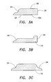
- FIG. 3A sectional view of a ceiling tile.
- FIG. 3B sectional view of a ceiling tile.
- FIG. 3C sectional view of a ceiling tile.
- FIG. 4 is an environmental, perspective view of a second embodiment of the foam faux tray ceiling system according to the present invention.
- FIG. 5 is an elevation view of the second embodiment of the foam faux tray ceiling system in its unassembled form.
- FIG. 6A is an elevation view of the attachment surface of a ceiling tile.
- FIG. 6B is an elevation view of the attachment surface of a ceiling tile.
- the foam faux tray ceiling system 10 consists of at least four tiles 12 a, 12 b, 12 c, 12 d preferably precut into lengths designed to form a rectangular soffit around the perimeter of a ceiling C.
- the soffit is formed by placing the tiles 12 a - 12 d around the perimeter of a ceiling with the tiles being connected at several joints 14 .
- the joints 14 are preferably sealed with joint compound and painted to match the tiles.
- the tiles 12 a - 12 d are made of a lightweight polymer foam material, such as polyurethane or polystyrene, are preferably glued and/or screwed to the ceiling C.
- Each tile 12 a - 12 d in the system 10 is substantially the same with different tiles varying only by length.
- the length of the tiles 12 a - 12 d are preferably between eight and sixteen feet, with widths preferably between six and eighteen inches.
- the tiles 12 a - 12 d are preferably about one inch thick, so that when the tiles 12 a - 12 d are applied to the ceiling C, the recess formed by the tiles 12 a - 12 d resembles an inverted tray.
- the aforementioned dimensions produce tiles with a much higher length to width ratio than existing ceiling tiles. It will be understood that the aforegoing dimensions are by way of illustration, and actual dimensions may vary.
- FIG. 2 shows the system 10 in an unassembled condition. Due to the similarity of the tiles 12 a - 12 d the following description of tile 12 a applies generally to all tiles in the system.
- Tile 12 a is trapezoidal in shape and has a decorative surface 20 , an opposing attachment surface 22 (FIG. 3A), an inner edge 24 which faces towards the interior of the ceiling, an outer edge 26 which abuts the wall, and two opposing connection edges 28 which are joined to adjacent tiles 12 b and 12 d in the completed tray ceiling. Angles ⁇ and ⁇ , formed by the outer edge 26 and the connecting edges 28 , are preferably forty-five degrees.
- the connection edges 28 are flat and form miter joints when positioned adjacent to the connection edges 28 of other tiles 12 b - 12 d. One skilled in the art could alter the connection edges 28 so as to form butt joints or interlocking lap joints between adjacent tiles.
- FIG. 3A is a sectional view of tile 12 a.
- the tile 12 a is approximately one inch thick and has a smooth finished decorative inner edge 24 .
- the outer edge 26 is ordinarily flat and defines a ninety degree dihedral angle with the attachment surface 22 .
- FIGS. 3B and 3C detail sectional views of two tiles 13 , 15 with possible variations of the outer 26 and inner 24 edges shown on tile 12 a, in FIG. 3A.
- the outer edge 26 of tile 13 shown in FIG. 3B, is cove formed.
- FIG. 3C details a tile 15 which has symmetrically shaped outer 26 and inner edges 24 .
- the inner edge 24 of the ceiling tiles may exhibit any of a variety of ornamental or decorative faux designs molded into the inner edge 24 during manufacture of the ceiling tile, e.g., a tooth design with alternate teeth projecting towards the interior of the ceiling, an egg and dart design, etc.
- the ceiling tiles 12 a - 12 d are manufactured as pre-formed, integral pieces by casting, molding, foam reservoir molding, elastic reservoir molding, or other plastic forming processes.
- FIG. 4 details an environmental perspective of a second embodiment 40 of the foam faux tray ceiling system.
- This embodiment has at least eight pieces including, four edge tiles 32 a, 32 b, 32 c, 32 d and four corner tiles 30 a, 30 b, 30 c, 30 d.
- the tiles are positioned to form a soffit around the perimeter of a ceiling and are preferably glued and/or screwed in place.
- the soffit is created by placing the corner tiles 30 a - 30 d in the corners of the ceiling C and disposing the edge tiles 32 a, 32 b, 32 c, 32 d between the corner tiles.
- the butt joints 14 formed between the tiles are preferably sealed with joint compound and painted.
- FIG. 5 shows the second embodiment 40 of the foam faux tray ceiling system in its unassembled form.
- the four corner tiles 30 a - 30 d are identical, therefore the following description of tile 30 a applies to all the corner tiles.
- Corner tile 30 a has a decorative surface 42 , an opposing attachment surface 44 , two connection edges 46 , two outer edges 48 , and two inner edges 49 .
- the two outer edges 48 and the two inner edges 49 may be beveled, coved or flat as described in FIGS. 3 A- 3 C herein above.
- the connection edges 46 as with the connection edges 28 , 30 in the first embodiment, may be altered to form miter joints or interlocking joints with the edges of adjacent tiles.
- edge tiles 32 a - 32 d differ from each other only by length, so the description of tile 32 a is applicable to all edge tiles.
- Edge tile 32 a is rectangular in shape and has a decorative surface 50 , an opposing attachment surface 52 , an inner edge 54 , an outer edge 56 , and two attachment edges 58 .
- the outer edge 56 and inner edge 54 may also be beveled, coved, or flat as described in FIGS. 3 A- 3 C herein above, and the inner edge 54 may have decorative faux designs molded therein during fabrication of the edge tiles 32 a - 32 d.
- the tile 32 a is preferably between eight and sixteen feet long and six to eighteen inches wide. These dimensions create a tile with a higher length to width ration that existing ceiling tiles.
- FIGS. 6A and 6B detail optional designs for the attachment surfaces for tiles 12 a - 12 d and 32 a - 32 d.
- FIG. 6A details several score lines 60 running along the attachment surface of the tile 12 a.
- the score lines 60 may be marked by indicia to indicate the distance of the score line from the connection edge, and are aligned parallel to one connection edge 28 .
- the score lines 60 serve as reference lines for cutting the tiles for non-standard sized applications.
- FIG. 6B shows the score lines 60 for tiles 32 a - 32 d for the second embodiment 40 of the present invention.
- the score lines run parallel to the connection edges 58 (not shown).
- the parts of the two embodiments may be joined into a single kit, and that the ceiling tiles may be made with one end mitered and the other end straight, so that the tray ceiling may have miter joints in the corners and a plurality of ceiling tiles placed end to end by but joints, depending upon the length of a side of the ceiling.
Landscapes
- Engineering & Computer Science (AREA)
- Architecture (AREA)
- Civil Engineering (AREA)
- Structural Engineering (AREA)
- Physics & Mathematics (AREA)
- Electromagnetism (AREA)
- Finishing Walls (AREA)
Abstract
A foam faux tray ceiling system having elongated tiles shaped and sized so as to be joinable to one another and thereby form a faux tray ceiling. Each tile is made of a lightweight polymer foam and has a decorative surface, attachment surface, inner edge, outer edge, and two connection edges. The inner edges are preferably decoratively finished and the outer edges are flat.
Description
- This application claims the benefit of U.S. Provisional Patent Application Serial No. 60/371,394, filed Apr. 11, 2002.
- 1. Field of the Invention
- The present invention relates to building construction and interior design, in particular to a foam faux tray ceiling system for new and existing homes.
- 2. Description of Related Art
- A conventional home ceiling is flat with a standard height of eight feet, although specialty ceilings may be constructed in a variety of shapes and sizes to appeal to a particular buyer. Unfortunately, specialty ceilings, such as gabled or vaulted ceilings, are often much more expensive than a conventional ceiling, and the price is even higher when replacing an existing conventional ceiling with a specialty ceiling. The present invention teaches the use of ceiling forms to create the look of a particular type of specialty ceiling known in the trade as a tray ceiling, without the associated costs or need for construction expertise as is ordinarily required.
- The present invention pertains to tray ceilings. A room with a tray ceiling has a vertical or angled edge soffit around its ceiling's perimeter and a flat ceiling above that. Some have described a tray ceiling as resembling a room covered by an upside down tray. Presently, tray ceilings are created by cutting wallboard into shaped pieces and attaching the pieces with nails and plaster around the perimeter of an existing traditional ceiling. Molding pieces would then have to be placed along the internal edges of the wallboard to finish the look. The problem with this system is that cutting, shaping and hanging wallboard is a difficult and time consuming process. The average homeowner often lacks the skill and tools necessary to create a presentable tray ceiling with these traditional methods. Also, many homeowners do not have the strength to lift and handle large pieces of uncut wallboard.
- There are a number of patents which disclose a variety of material which may be used as suspended ceiling tiles or as moldings attached to ceilings. None of the following patents disclosed the used of preformed, light weight, foam pieces to create a tray ceiling.
- For example, U.S. Pat. No. RE37,436 to Santarossa teaches a method of manufacturing an elongated decorative molding having a decorative surface and a desired cross-sectional profile. The Santarossa patent describes moldings and does not suggest a system of interlocking foam tiles for creating a tray ceiling.
- U.S. Pat. No. 6,197,235 to Miller et al. discloses a method of manufacture for textured surface panels and panel products made from gypsum fiberboard. This patent teaches forming shaped panels for ceilings but does not show a system of decorative edges and interconnecting pieces that allow for the easily assembly of a tray ceiling as in the present invention. In addition, elongated strips of gypsum fiberboard would be too heavy for convenient, one-person assembly to a ceiling to form a tray ceiling.
- U.S. Pat. No. 6,117,514 to Herrmann discloses a ceiling tile system for providing a light-weight and easy-to-form interlocking plastic ceiling tile system for covering a ceiling. The tile in this patent are made of a very thin plastic sheeting capable of thermal vacuum forming to define reliefs in the sheeting. As such, the ceiling tiles described by Herrmann are not suitable to form a faux tray ceiling with a decorative interior edge, nor are they constructed of light weight foam.
- None of the above inventions and patents, taken either singly or in combination, is seen to describe the instant invention as claimed.
- The present invention is a tray ceiling system comprising a plurality of elongated, prefabricated, polymer foam ceiling tiles. Each tile has a decorative surface, an opposing attachment surface, a inside edge, and outside edge, and two connecting edges. The inside edges face the interior of the ceiling and are smoothly finished into a decorative shape (bevel, cove, etc.), while the outside edge faces the wall and may either be a decorative bevel or be adapted for abutment to a wall. The connecting edges may be orthogonal to the length of the tile to form butt joints, or may be at a forty-five degree angle to the length of the tile to form miter joints. The tiles are elongated, preferably between eight and sixteen feet in length, and range in width preferably between six to eighteen inches. The tiles are made from a lightweight foam material, e.g., polyurethane, polystyrene, etc., so that the tiles may be easily installed on the ceiling.
- When in use construction adhesive is applied to the attachment surface and the tiles are positioned around the perimeter of a ceiling. The mitered connection edges are positioned adjacent to one another thereby forming right angles that fit into the corners of the ceiling. The light weight of the tiles allows them to be easily manipulated and attached to the ceiling by one person. The smoothly finished inside and outside edges would eliminate the need for molding or for drywall tape and joint compound required to finish edges of drywall or wallboard ceiling tiles. Narrower tiles may be attached to wider tiles to create a stepped look.
- Accordingly, it is a principal object of the invention to provide a lightweight alternative to existing tray ceiling construction systems.
- It is another object of the invention to provide a tray ceiling system that does not require more than an average amount of upper body strength to install.
- It is a further object of the invention to provide a tray ceiling system that is easy to install by unskilled workers.
- Still another object of the invention is to provide a tray ceiling system that can be installed without tools or with a minimum of simple tools.
- It is an object of the invention to provide improved elements and arrangements thereof in an apparatus for the purposes described which is inexpensive, dependable and fully effective in accomplishing its intended purposes.
- These and other objects of the present invention will become readily apparent upon further review of the following specification and drawings.
- FIG. 1 is an environmental, perspective view of the foam faux tray ceiling system according to the present invention.
- FIG. 2 is an elevation view of the tray ceiling system in its unassembled form.
- FIG. 3A sectional view of a ceiling tile.
- FIG. 3B sectional view of a ceiling tile.
- FIG. 3C sectional view of a ceiling tile.
- FIG. 4 is an environmental, perspective view of a second embodiment of the foam faux tray ceiling system according to the present invention.
- FIG. 5 is an elevation view of the second embodiment of the foam faux tray ceiling system in its unassembled form.
- FIG. 6A is an elevation view of the attachment surface of a ceiling tile.
- FIG. 6B is an elevation view of the attachment surface of a ceiling tile.
- Similar reference characters denote corresponding features consistently throughout the attached drawings.
- The foam faux
tray ceiling system 10, consists of at least fourtiles several joints 14. Thejoints 14 are preferably sealed with joint compound and painted to match the tiles. The tiles 12 a-12 d are made of a lightweight polymer foam material, such as polyurethane or polystyrene, are preferably glued and/or screwed to the ceiling C. - Each tile 12 a-12 d in the
system 10 is substantially the same with different tiles varying only by length. The length of the tiles 12 a-12 d are preferably between eight and sixteen feet, with widths preferably between six and eighteen inches. The tiles 12 a-12 d are preferably about one inch thick, so that when the tiles 12 a-12 d are applied to the ceiling C, the recess formed by the tiles 12 a-12 d resembles an inverted tray. The aforementioned dimensions produce tiles with a much higher length to width ratio than existing ceiling tiles. It will be understood that the aforegoing dimensions are by way of illustration, and actual dimensions may vary. - FIG. 2 shows the
system 10 in an unassembled condition. Due to the similarity of the tiles 12 a-12 d the following description oftile 12 a applies generally to all tiles in the system.Tile 12 a is trapezoidal in shape and has adecorative surface 20, an opposing attachment surface 22 (FIG. 3A), aninner edge 24 which faces towards the interior of the ceiling, anouter edge 26 which abuts the wall, and two opposing connection edges 28 which are joined toadjacent tiles outer edge 26 and the connectingedges 28, are preferably forty-five degrees. The connection edges 28 are flat and form miter joints when positioned adjacent to the connection edges 28 ofother tiles 12 b-12 d. One skilled in the art could alter the connection edges 28 so as to form butt joints or interlocking lap joints between adjacent tiles. - FIG. 3A is a sectional view of
tile 12 a. Thetile 12 a is approximately one inch thick and has a smooth finished decorativeinner edge 24. Theouter edge 26 is ordinarily flat and defines a ninety degree dihedral angle with theattachment surface 22. - FIGS. 3B and 3C detail sectional views of two
tiles tile 12 a, in FIG. 3A. Theouter edge 26 oftile 13, shown in FIG. 3B, is cove formed. FIG. 3C details atile 15 which has symmetrically shaped outer 26 andinner edges 24. - The aforementioned variations are intended to show a sample of the wide variety of edge variations which could be created by one skilled in the art and are not intended to limit the present invention to any particular edge design. In particular, the
inner edge 24 of the ceiling tiles may exhibit any of a variety of ornamental or decorative faux designs molded into theinner edge 24 during manufacture of the ceiling tile, e.g., a tooth design with alternate teeth projecting towards the interior of the ceiling, an egg and dart design, etc. The ceiling tiles 12 a-12 d are manufactured as pre-formed, integral pieces by casting, molding, foam reservoir molding, elastic reservoir molding, or other plastic forming processes. - FIG. 4 details an environmental perspective of a
second embodiment 40 of the foam faux tray ceiling system. This embodiment has at least eight pieces including, fouredge tiles corner tiles edge tiles - FIG. 5 shows the
second embodiment 40 of the foam faux tray ceiling system in its unassembled form. The four corner tiles 30 a-30 d are identical, therefore the following description oftile 30 a applies to all the corner tiles.Corner tile 30 a has adecorative surface 42, an opposingattachment surface 44, two connection edges 46, twoouter edges 48, and twoinner edges 49. The twoouter edges 48 and the twoinner edges 49 may be beveled, coved or flat as described in FIGS. 3A-3C herein above. The connection edges 46, as with the connection edges 28, 30 in the first embodiment, may be altered to form miter joints or interlocking joints with the edges of adjacent tiles. - The edge tiles 32 a-32 d differ from each other only by length, so the description of
tile 32 a is applicable to all edge tiles.Edge tile 32 a is rectangular in shape and has adecorative surface 50, an opposingattachment surface 52, aninner edge 54, anouter edge 56, and two attachment edges 58. Theouter edge 56 andinner edge 54 may also be beveled, coved, or flat as described in FIGS. 3A-3C herein above, and theinner edge 54 may have decorative faux designs molded therein during fabrication of the edge tiles 32 a-32 d. Thetile 32 a is preferably between eight and sixteen feet long and six to eighteen inches wide. These dimensions create a tile with a higher length to width ration that existing ceiling tiles. - FIGS. 6A and 6B detail optional designs for the attachment surfaces for tiles 12 a-12 d and 32 a-32 d. FIG. 6A details
several score lines 60 running along the attachment surface of thetile 12 a. The score lines 60 may be marked by indicia to indicate the distance of the score line from the connection edge, and are aligned parallel to oneconnection edge 28. The score lines 60 serve as reference lines for cutting the tiles for non-standard sized applications. FIG. 6B shows the score lines 60 for tiles 32 a-32 d for thesecond embodiment 40 of the present invention. The score lines run parallel to the connection edges 58 (not shown). - It will be understood that the parts of the two embodiments may be joined into a single kit, and that the ceiling tiles may be made with one end mitered and the other end straight, so that the tray ceiling may have miter joints in the corners and a plurality of ceiling tiles placed end to end by but joints, depending upon the length of a side of the ceiling.
- It is to be understood that the present invention is not limited to the sole embodiments described above, but encompasses any and all embodiments within the scope of the following claims.
Claims (12)
1. A foam faux tray ceiling system, comprising;
a plurality of prefabricated, elongated ceiling tiles sized and dimensioned for forming a rectangular border about a ceiling defining a tray, each tile having a decorative face and an opposing faced adapted for attachment to the ceiling; and
wherein said tiles are made of lightweight polymer foam.
2. The foam faux tray ceiling system according to claim 1 , wherein each said ceiling tile is trapezoidal in shape, the angle between the outer edge and each connection edge being about 45 degrees, whereby adjoining ceiling tiles form a miter joint at corners of the ceiling.
3. The foam faux tray ceiling system according to claim 1 , wherein each of said ceiling tiles has a decoratively shaped inner edge facing the interior of the rectangular border.
4. The foam faux tray ceiling system according to claim 1 , wherein each of said ceiling tiles has a pair of straight edges for forming butt joints with adjoining ceiling tiles.
5. The foam faux tray ceiling system according to claim 4 , further comprising a plurality of rectangular corner ceiling tiles for attachment to ceiling corners, said elongated ceiling tiles forming butt joints with said corner tiles.
6. The foam faux tray ceiling system according to claim 1 , wherein each said ceiling tile has a length between about eight feet and sixteen feet.
7. The foam faux tray ceiling system according to claim 1 , wherein each said ceiling tile has a width between about six inches and eighteen inches.
8. The foam faux tray ceiling system according to claim 1 , wherein each said ceiling tile has a thickness of about one inch.
9. The foam faux tray ceiling system according to claim 1 , wherein each said ceiling tile is made from polyurethane foam.
10. The foam faux tray ceiling system according to claim 1 , wherein each said ceiling tile is made from polystyrene foam.
11. The foam faux tray ceiling system according to claim 1 , wherein each of said ceiling tiles has a decoratively shaped inner edge facing the interior of the rectangular border and a decoratively shaped outer edge facing the exterior of the rectangular border.
12. The foam faux tray ceiling system according to claim 1 , wherein each opposing face of said ceiling tiles is marked with measurement lines.
Priority Applications (3)
| Application Number | Priority Date | Filing Date | Title |
|---|---|---|---|
| US10/206,775 US6723419B2 (en) | 2002-04-11 | 2002-07-29 | Foam faux tray ceiling system |
| PCT/US2003/010239 WO2003086745A1 (en) | 2002-04-11 | 2003-04-02 | Foam faux tray ceiling system |
| AU2003235448A AU2003235448A1 (en) | 2002-04-11 | 2003-04-02 | Foam faux tray ceiling system |
Applications Claiming Priority (2)
| Application Number | Priority Date | Filing Date | Title |
|---|---|---|---|
| US37139402P | 2002-04-11 | 2002-04-11 | |
| US10/206,775 US6723419B2 (en) | 2002-04-11 | 2002-07-29 | Foam faux tray ceiling system |
Publications (2)
| Publication Number | Publication Date |
|---|---|
| US20030194535A1 true US20030194535A1 (en) | 2003-10-16 |
| US6723419B2 US6723419B2 (en) | 2004-04-20 |
Family
ID=28794092
Family Applications (1)
| Application Number | Title | Priority Date | Filing Date |
|---|---|---|---|
| US10/206,775 Expired - Lifetime US6723419B2 (en) | 2002-04-11 | 2002-07-29 | Foam faux tray ceiling system |
Country Status (3)
| Country | Link |
|---|---|
| US (1) | US6723419B2 (en) |
| AU (1) | AU2003235448A1 (en) |
| WO (1) | WO2003086745A1 (en) |
Cited By (6)
| Publication number | Priority date | Publication date | Assignee | Title |
|---|---|---|---|---|
| USD550043S1 (en) * | 2006-09-08 | 2007-09-04 | Cambro Manufacturing Company | Food service tray |
| USD565905S1 (en) * | 2007-06-21 | 2008-04-08 | Playtex Products, Inc. | Plate and base assembly |
| EP2063038A3 (en) * | 2007-11-22 | 2012-10-10 | Pinta acoustic GmbH | Cover absorber element |
| USD822281S1 (en) * | 2015-11-12 | 2018-07-03 | Shiseido Co., Ltd. | Tray |
| USD1098499S1 (en) * | 2024-07-19 | 2025-10-14 | Westlake Royal Building Products (Usa) Inc. | Trim board |
| USD1103419S1 (en) * | 2024-07-19 | 2025-11-25 | Westlake Royal Building Products (Usa) Inc. | Trim board |
Families Citing this family (11)
| Publication number | Priority date | Publication date | Assignee | Title |
|---|---|---|---|---|
| US20030168760A1 (en) * | 2002-03-08 | 2003-09-11 | Salvatore Badalamenti | Method of making and assembling foam crown molding |
| US20050166506A1 (en) * | 2003-12-30 | 2005-08-04 | Morelissen Jacob H. | Ceiling tile |
| US20060179765A1 (en) * | 2005-01-31 | 2006-08-17 | Howard Meghan L | Adaptable ceiling tile system |
| US20070079562A1 (en) * | 2003-12-30 | 2007-04-12 | Buck Frederick A | Ceiling tile assembly |
| EP1904695B1 (en) * | 2005-07-20 | 2011-02-02 | Armstrong World Industries, Inc. | Suspension systems |
| US20090064620A1 (en) * | 2007-09-10 | 2009-03-12 | Launs Ronald E | Tray Ceiling System |
| USD628733S1 (en) | 2009-12-23 | 2010-12-07 | Cobb Iii Hugh W | Illuminated tile assembly |
| US8136321B1 (en) | 2011-03-17 | 2012-03-20 | Jeffrey Bauman | Decorative ceiling/wall panel |
| US8667753B1 (en) | 2011-06-17 | 2014-03-11 | David A. Holmgren | Sculpted room system |
| US8800228B2 (en) * | 2011-06-17 | 2014-08-12 | Sculpted Room Design, LLC | Sculpted room system |
| US9089229B2 (en) * | 2012-07-26 | 2015-07-28 | Hewlett-Packard Development Company, L.P. | Frame kits and frames |
Family Cites Families (9)
| Publication number | Priority date | Publication date | Assignee | Title |
|---|---|---|---|---|
| US2778658A (en) * | 1954-07-27 | 1957-01-22 | Acme Visible Records Inc | Flexible index strips in sheet form |
| US3251164A (en) * | 1963-07-16 | 1966-05-17 | Lyle E Wright | Ceiling of plural planks with elongated embedded hanger members |
| US3481092A (en) * | 1968-02-01 | 1969-12-02 | Lilly Co Eli | Ceiling molding |
| US5508103A (en) * | 1995-01-30 | 1996-04-16 | Marley Mouldings Inc. | Extrusion product with decorative enhancement and process of making the same |
| US5672391A (en) | 1995-08-28 | 1997-09-30 | 888804 Ontario Limited | Method of manufacturing foam core moldings |
| KR19990063600A (en) * | 1995-09-25 | 1999-07-26 | 휴스톤 로버트 엘 | Reinforcement Insulation Panel |
| KR100509071B1 (en) * | 1996-07-26 | 2005-08-18 | 케스케이드 엔지니어링 인코퍼레이티드 | System and method for fastening insulating layer to sheet material |
| US6197235B1 (en) | 1999-02-09 | 2001-03-06 | United States Gypsum Company | Method of manufacture for textured surface panels and panel products made therefrom |
| US6117514A (en) | 1999-05-13 | 2000-09-12 | Herrmann; Richard J. | Ceiling tile system |
-
2002
- 2002-07-29 US US10/206,775 patent/US6723419B2/en not_active Expired - Lifetime
-
2003
- 2003-04-02 AU AU2003235448A patent/AU2003235448A1/en not_active Abandoned
- 2003-04-02 WO PCT/US2003/010239 patent/WO2003086745A1/en not_active Ceased
Cited By (6)
| Publication number | Priority date | Publication date | Assignee | Title |
|---|---|---|---|---|
| USD550043S1 (en) * | 2006-09-08 | 2007-09-04 | Cambro Manufacturing Company | Food service tray |
| USD565905S1 (en) * | 2007-06-21 | 2008-04-08 | Playtex Products, Inc. | Plate and base assembly |
| EP2063038A3 (en) * | 2007-11-22 | 2012-10-10 | Pinta acoustic GmbH | Cover absorber element |
| USD822281S1 (en) * | 2015-11-12 | 2018-07-03 | Shiseido Co., Ltd. | Tray |
| USD1098499S1 (en) * | 2024-07-19 | 2025-10-14 | Westlake Royal Building Products (Usa) Inc. | Trim board |
| USD1103419S1 (en) * | 2024-07-19 | 2025-11-25 | Westlake Royal Building Products (Usa) Inc. | Trim board |
Also Published As
| Publication number | Publication date |
|---|---|
| WO2003086745A1 (en) | 2003-10-23 |
| AU2003235448A1 (en) | 2003-10-27 |
| US6723419B2 (en) | 2004-04-20 |
Similar Documents
| Publication | Publication Date | Title |
|---|---|---|
| US6723419B2 (en) | Foam faux tray ceiling system | |
| US5179811A (en) | Decorative trimming system | |
| USRE47694E1 (en) | Wall panel | |
| US5836123A (en) | Vinyl-siding corner block | |
| US3621625A (en) | Brick siding | |
| US7784233B2 (en) | Molding assembly, modular molding system, and methods for using the same | |
| CA1313461C (en) | Panel system and method | |
| US7757450B2 (en) | Control joint | |
| US7914878B2 (en) | Grooved, corner-ready wall base | |
| EP1960612A1 (en) | Modular stone panel | |
| US6332296B1 (en) | Corner apparatus and method for forming corners of wallboard constructed walls | |
| US7793474B2 (en) | Over-mount corner | |
| CA2503419A1 (en) | Building siding | |
| US5419093A (en) | Versatile aluminum alloy molding block structure | |
| US6199332B1 (en) | Log facade | |
| US6802163B2 (en) | Plant-on building enhancement | |
| US7743571B2 (en) | Injection moldable composite gable vent | |
| US6331337B1 (en) | Bonding building blocks using adhesive tapes | |
| US5382393A (en) | Method and apparatus for forming chamfered outside corners on concrete products | |
| KR20130105586A (en) | Indoor molding to be installed to finish as finishing materials the indoor of architecture and installation method of indoor molding | |
| US20090064620A1 (en) | Tray Ceiling System | |
| JPH0253582B2 (en) | ||
| US20040020151A1 (en) | Snap track decorative moldings | |
| US11384537B2 (en) | Suspended ceiling system incorporating key and keyhole combinations and method of installing same | |
| KR200164459Y1 (en) | Structure of sides of construction tile |
Legal Events
| Date | Code | Title | Description |
|---|---|---|---|
| STCF | Information on status: patent grant |
Free format text: PATENTED CASE |
|
| FPAY | Fee payment |
Year of fee payment: 4 |
|
| FPAY | Fee payment |
Year of fee payment: 8 |
|
| FEPP | Fee payment procedure |
Free format text: PATENT HOLDER CLAIMS MICRO ENTITY STATUS, ENTITY STATUS SET TO MICRO (ORIGINAL EVENT CODE: STOM); ENTITY STATUS OF PATENT OWNER: MICROENTITY |
|
| FPAY | Fee payment |
Year of fee payment: 12 |