US20030194312A1 - Flush tenon cover for steam turbine blades with advanced sealing - Google Patents
Flush tenon cover for steam turbine blades with advanced sealing Download PDFInfo
- Publication number
- US20030194312A1 US20030194312A1 US10/119,291 US11929102A US2003194312A1 US 20030194312 A1 US20030194312 A1 US 20030194312A1 US 11929102 A US11929102 A US 11929102A US 2003194312 A1 US2003194312 A1 US 2003194312A1
- Authority
- US
- United States
- Prior art keywords
- cover
- tenon
- tooth
- buckets
- recess
- Prior art date
- Legal status (The legal status is an assumption and is not a legal conclusion. Google has not performed a legal analysis and makes no representation as to the accuracy of the status listed.)
- Granted
Links
- 238000007789 sealing Methods 0.000 title abstract description 8
- 239000002245 particle Substances 0.000 abstract description 15
- 239000007787 solid Substances 0.000 abstract description 14
- 230000003628 erosive effect Effects 0.000 abstract description 12
- 230000003247 decreasing effect Effects 0.000 abstract 1
- 239000000463 material Substances 0.000 description 8
- 238000003754 machining Methods 0.000 description 7
- 235000001674 Agaricus brunnescens Nutrition 0.000 description 1
- 230000003190 augmentative effect Effects 0.000 description 1
- 230000015572 biosynthetic process Effects 0.000 description 1
- 238000004519 manufacturing process Methods 0.000 description 1
- 238000012986 modification Methods 0.000 description 1
- 230000004048 modification Effects 0.000 description 1
Images


Classifications
-
- F—MECHANICAL ENGINEERING; LIGHTING; HEATING; WEAPONS; BLASTING
- F01—MACHINES OR ENGINES IN GENERAL; ENGINE PLANTS IN GENERAL; STEAM ENGINES
- F01D—NON-POSITIVE DISPLACEMENT MACHINES OR ENGINES, e.g. STEAM TURBINES
- F01D11/00—Preventing or minimising internal leakage of working-fluid, e.g. between stages
- F01D11/02—Preventing or minimising internal leakage of working-fluid, e.g. between stages by non-contact sealings, e.g. of labyrinth type
-
- F—MECHANICAL ENGINEERING; LIGHTING; HEATING; WEAPONS; BLASTING
- F01—MACHINES OR ENGINES IN GENERAL; ENGINE PLANTS IN GENERAL; STEAM ENGINES
- F01D—NON-POSITIVE DISPLACEMENT MACHINES OR ENGINES, e.g. STEAM TURBINES
- F01D5/00—Blades; Blade-carrying members; Heating, heat-insulating, cooling or antivibration means on the blades or the members
- F01D5/12—Blades
- F01D5/22—Blade-to-blade connections, e.g. for damping vibrations
- F01D5/225—Blade-to-blade connections, e.g. for damping vibrations by shrouding
Definitions
- the present invention relates to steam turbines and more particularly to a steam turbine cover for minimizing or eliminating solid particle erosion of bucket tenons and to improve sealing efficiency.
- bucket covers are typically attached to the buckets by peening the tenon projecting from the end of the bucket and through an aperture in the bucket cover.
- This peening operation results in a projecting bulb or knob on the outside diameter of the cover.
- This raised knob or projection can be eroded by solid particles in the steam path. As a result, the cover may become loose, crack or separate from the buckets.
- the raised knob or projection, resulting from peening the tenon substantially prevents the application of one or more labyrinth seal teeth along the outside face of the cover, particularly on units with large differential expansion between the stationary and rotating components.
- the knob or projection of the peened tenon is disposed below the outer surface or outer diameter of the cover. While that configuration enabled the application of sealing teeth configurations to the cover, it is limited to straight tooth or flat surface geometry. Under certain conditions, solid particles may become trapped within the confines of the recess and between the walls defining the recess and the tenon. These trapped particles tend to erode the tenon knob or projection very quickly and have been shown, in certain circumstances, to essentially cut through the tenon.
- Another bucket/cover design includes the integral formation of the bucket and cover. While this design incorporates the necessary sealing options, i.e., application of one or more labyrinth seal teeth, and also minimizes or eliminates the concern for solid particle erosion, the integral bucket/cover combination is costly to manufacture and complex. Accordingly, there has arisen a need for a bucket/tenon/cover design that both eliminates or minimizes solid particle erosion, as well as affords sealing efficiencies without complexity or excessive costs.
- a steam turbine a plurality of buckets mounted on a rotating component, e.g., a rotor, and a plurality of covers mounted on the tips of the buckets, the buckets having tenons peened to secure the buckets to the covers.
- At least one recess is preferably formed in the outer cover surface to form a profiled surface and at least one tooth projects either radially outwardly from the profiled surface or radially inwardly from the registering stationary component.
- the profiled surface includes at least one recess defined at least in part by the tenon.
- the profiled surface includes a tooth projecting from the outer surface of the cover toward the stationary component and including at least part of the tenon. It will be appreciated that the recess or the tooth each formed, at least in part, by the tenon extend in a circumferential direction about the cover. To form this preferred configuration, the outer surface of the cover is machined such that the tenon forms part of the recess or the labyrinth tooth, as applicable.
- a seal between the buckets and the stationary component comprising a cover mounted on a radial outer end of at least one bucket and having an opening, one bucket having a tenon projecting from the outer end of one bucket and extending into the cover opening, an outer surface of the cover and an outer end surface of the tenon forming a profiled surface in opposition to the stationary component with contiguous surfaces of the tenon end and the cover lying flush with one another, the profiled surface including at least one of a recess formed in the profiled surface and a tooth projecting radially outwardly of the profiled surface.
- a seal between the buckets and the stationary component comprising a plurality of covers mounted on radial outer ends of the buckets arranged in an annular array thereof with one or more buckets being secured to each cover, each cover having at least one opening and each bucket having a tenon projecting from the outer end thereof into the opening, an outer surface of each cover and an outer end face of each tenon forming a profiled surface in opposition to the stationary component with contiguous surfaces of the tenon end faces and the outer cover surface lying flush with one another.
- a seal between the buckets and the stationary component comprising a plurality of covers mounted on radial outer ends of the buckets arranged in an annular array thereof with one or more buckets being secured to each cover, each cover having at least one opening and each bucket having a tenon projecting from the outer end thereof into the opening, an outer surface of each cover and an outer end face of each tenon forming a profiled surface in opposition to the stationary component with contiguous surfaces of the tenon end faces and the outer cover surface lying flush with one another, the profiled surface including at least one recess, the profiled surface including a tooth projecting radially outwardly thereof.
- FIG. 1 is a fragmentary axial view illustrating a plurality of buckets with an attached cover
- FIG. 2 is a fragmentary enlarged view illustrating the tenons and openings through the cover prior to assembly
- FIG. 3 is a fragmentary cross-sectional view illustrating a flush tenon cover/bucket connection
- FIGS. 4 - 11 are fragmentary side elevational views of buckets, tenons, covers, and registering stationary components with parts in cross-section, illustrating various forms of the flush tenon bucket/cover design with advanced sealing according to the present invention.
- FIG. 1 there is illustrated a plurality of buckets 10 forming part of a rotating component of a rotor, generally indicated 12 , of a steam turbine.
- Covers 14 are secured to outer tips of the buckets, the covers extending in a circumferential direction.
- the tips of the buckets 10 have one or more tenons 16 projecting radially outwardly of the tips.
- Each cover 14 is typically provided in an arcuate circumferentially extending segment for spanning a plurality of buckets, for example, four or five buckets, and has openings 18 for receiving the tenons. The tenons are received in the openings 18 and peened and may be machined to form a flush cover design, as illustrated in FIG. 3.
- FIGS. 4 - 11 like parts are designated by like reference numerals, preceded by a numeral identifying that embodiment.
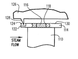
- a bucket 110 having a tenon 116 projecting from a tip thereof for engaging in an opening 118 of a cover 114 .
- the outer surface of the cover at the location of the tenon is machined to remove the projecting portion or mushroom of the tenon to provide a flush cover/tenon configuration.
- the leading edge 122 of the cover 114 is provided with a recess 124 formed by a machining process and which recess extends circumferentially the full length of the segment. It will therefore be appreciated that the recess 124 extends circumferentially around the entire periphery of the rotary component, with the recess 124 in each cover 114 forming a continuation of the recesses 124 of adjoining covers 114 .
- the stationary component 126 is provided with a projecting labyrinth tooth 128 which likewise extends the entire circumferential extent about the cover.
- the tooth 128 is axially located on the stationary component 136 to project into the recess 124 such that its tip lies radially inwardly of the outer surface 130 of cover 114 . Consequently, by utilizing a flush tenon/cover design in combination with a recessed leading edge receiving a labyrinth tooth, the flow coefficient across the gap between the stationary component and the cover is changed, affording a reduced pressure drop, which reduces leakage flow, as well as solid particle erosion.
- the bucket 210 , tenon 216 , openings 218 and cover 214 are similar to the corresponding bucket, tenon and cover of FIG. 4, except that instead of a leading edge recess 124 as in FIG. 4, the trailing edge 232 of cover 214 is provided with a circumferentially extending recess 234 .
- a labyrinth tooth 228 projects radially inwardly from the stationary component 226 into the recess 234 radially inwardly of the outer surface 230 of the cover 214 .
- the recesses of the covers and the labyrinth tooth extend 360° about the periphery of the rotor and stationary component. Consequently, a significant pressure drop across the gap between the cover and the stationary component occurs, reducing the magnitude of the steam flow and, hence, the capacity for solid particle erosion.
- FIG. 6 there is illustrated a bucket 310 having a tenon 316 projecting through an opening 318 of a cover 314 .
- the tenon/cover is flush along the outer profiled surface 330 of the cover.
- the cover 314 has an increased radial thickness (in comparison with the thicknesses of the covers illustrated in FIGS. 4 and 5) to enable the outer surface of the cover, as well as portions of the tenon, to be machined to form circumferentially extending recesses about the rotary component.
- two recesses 336 and 338 are machined into the outer surface of the cover 314 to form the profiled surface 330 , the recesses extending the entire circumferential distance about the rotary component.
- a portion of the tenon 316 is likewise machined on axially opposite sides of the tenon 316 to form the recesses 336 and 338 .
- the dashed lines in FIG. 6 represent the extent of the cover prior to machining, while the full lines represent the finished cover and tenon with the profiled surface 330 .
- both the cover portions of the and tenon are machined to form the recesses 336 and 338 .
- portions of the cover between circumferentially adjacent tenons lie flush with the outer surfaces of the tenons 316 .
- the stationary component 326 has a plurality of axially spaced labyrinth teeth projecting radially inwardly toward the cover. Teeth 340 have a lesser radial extent than the teeth 342 , which project into the recesses 336 and 338 , respectively. Note also the intermediate short tooth 340 radially opposite the tenon 316 . Consequently, a profile is formed along the outer surface 330 of the cover 314 comprising the recesses 336 and 338 , as well as margins of the tenons 316 which have been cut away to form part of the recesses.
- the combined labyrinth seals and recesses provide increased pressure drop, reduced flow through the gap and, hence, reduce solid particle erosion.
- the bucket 410 has one or more tenons 416 projecting through one or more openings 418 in the cover 414 to form a flush cover/tenon design which improved sealing characteristics.
- the cover 414 is machined along its outer circumferential face to form a profile having a plurality of axially spaced labyrinth seal teeth 444 defining circumferentially extending recesses 446 between the spaced axial teeth.
- the one or more tenons 416 as well as portions of the cover circumferentially adjacent the tenons are machined below the initially provided surface 448 of the cover 414 to form the recess between the immediate pair of teeth 444 .
- the stationary component 426 also includes a plurality of axially spaced, radially inwardly extending labyrinth teeth 440 in radial opposition to the profiled outer surface of the cover 414 .
- the reduced steam flow and pressure drop across the gap between the rotating cover and stationary component thus effectively reduce solid particle erosion.
- a bucket 510 with a tenon 516 received in a tenon opening 518 in bucket cover 514 there is provided a bucket 510 with a tenon 516 received in a tenon opening 518 in bucket cover 514 .
- the outer surface of cover 514 has been machined to form a profiled surface 530 having a labyrinth tooth 548 projecting radially outwardly and lying adjacent the trailing edge 532 of the cover.
- the outer surface of the cover 514 including tenon 516 has been machined to provide a profiled surface including a labyrinth tooth 548 .
- a radially inwardly and circumferentially extending abradable material 550 there is provided.
- the bucket 610 includes one or more tenons 616 received in one or more openings 618 , respectively, of the cover 614 .
- a profile is formed along the outer surface of cover 614 by machining away material, indicated within the dashed line 646 , to form a plurality of axially spaced teeth 644 projecting from the flush surface of the tenon and outer cover surface.
- the intermediate tooth 644 is in part formed by machining the tenon 616 on axially opposite sides thereof. It will be appreciated that the teeth 644 extend continuously in a circumferential direction and that the intermediate tooth is formed of circumferential portions both of the tenon and the original material of the cover 614 .
- the stationary component 626 includes a plurality of axially spaced teeth 650 and 652 extending circumferentially in radial opposition to the profiled surface 630 of the cover 614 .
- the enlarged tooth 652 lies in radial registration with the recess 624 , while the radially reduced teeth 652 lie in radial opposition to the remaining portions of the profiled surface 630 , including the tenon.
- the bucket 710 includes one or more tenons 716 extending through one or more openings 718 in the bucket cover 714 .
- the outer surface 730 of the cover 714 is profiled by machining away material indicated within the dashed lines 746 to form a plurality of recesses extending circumferentially and axially spaced one from the other.
- a central recess 754 is provided by machining a recess along the outer surface of the cover 714 , including passing through the outer surface of the tenon(s) 716 .
- the recess 754 extends continuously in a circumferential direction and includes portions of the cover and tenons. Additional recesses 756 are formed on opposite sides of the central recess 754 .
- leading and trailing edge recesses 724 and 734 are formed in the outer profile of the leading and trailing edges 722 and 732 , respectively.
- the stationary component 726 includes a plurality of axially spaced teeth of various sizes, depending upon the nature of the profiled surface 730 of the cover in radial opposition to the teeth.
- the short teeth 760 lie in radial opposition to the original outer surface of the cover adjacent the tenon 716
- an intermediate-length, radially inwardly extending tooth 762 projects into the recess 754 formed by the tenons and the outer surface of the cover.
- Large radially inwardly extending teeth 764 project radially inwardly from the stationary component 726 into the leading and trailing edge recesses 724 and 734 , respectively.
- the bucket 810 includes one or more tenons 816 projecting through one or more openings 818 of a cover 814 .
- Cover 814 has a profiled outer surface 830 .
- the space within the dashed lines 846 represents material which has been machined away to form the profiled outer surface 830 .
- the outer surface of the cover has been machined to form a plurality of axially spaced radially outwardly projecting teeth 866 .
- the intermediate tooth 816 is formed in part by machining tenon 816 , as well as circumferentially adjacent outer portions of the cover.
- the stationary component 826 includes a plurality of axially spaced large and small teeth 868 and 870 .
- the large teeth 868 project radially inwardly into the recesses 824 and 834 along the respective leading and trailing edges 822 and 832 of the cover 814 .
- the smaller teeth 870 lie in radial registration with the spaces between the teeth 866 or may lie in opposition to the teeth 866 .
- the flush tenon/cover design is augmented by a profiled surface formed along the cover.
- the profiled surface includes one or more recesses, one or more teeth, or a combination of recesses and teeth. Additionally, in certain embodiments, the profiled surface is also formed by forming recesses in or teeth from the tenons, or both, so that portions of the machined tenons lie in circumferential flush relation with the recesses or teeth of the adjoining cover surfaces. In this manner, the leakage flow past the gap between the rotary and stationary components is reduced, with resulting reduction in the potential for solid particle erosion.
Landscapes
- Engineering & Computer Science (AREA)
- Mechanical Engineering (AREA)
- General Engineering & Computer Science (AREA)
- Turbine Rotor Nozzle Sealing (AREA)
Abstract
Description
- The present invention relates to steam turbines and more particularly to a steam turbine cover for minimizing or eliminating solid particle erosion of bucket tenons and to improve sealing efficiency.
- In conventional steam turbines, bucket covers are typically attached to the buckets by peening the tenon projecting from the end of the bucket and through an aperture in the bucket cover. This peening operation results in a projecting bulb or knob on the outside diameter of the cover. This raised knob or projection can be eroded by solid particles in the steam path. As a result, the cover may become loose, crack or separate from the buckets. Also, the raised knob or projection, resulting from peening the tenon, substantially prevents the application of one or more labyrinth seal teeth along the outside face of the cover, particularly on units with large differential expansion between the stationary and rotating components.
- In another cover-to-bucket design, the knob or projection of the peened tenon is disposed below the outer surface or outer diameter of the cover. While that configuration enabled the application of sealing teeth configurations to the cover, it is limited to straight tooth or flat surface geometry. Under certain conditions, solid particles may become trapped within the confines of the recess and between the walls defining the recess and the tenon. These trapped particles tend to erode the tenon knob or projection very quickly and have been shown, in certain circumstances, to essentially cut through the tenon.
- Another bucket/cover design includes the integral formation of the bucket and cover. While this design incorporates the necessary sealing options, i.e., application of one or more labyrinth seal teeth, and also minimizes or eliminates the concern for solid particle erosion, the integral bucket/cover combination is costly to manufacture and complex. Accordingly, there has arisen a need for a bucket/tenon/cover design that both eliminates or minimizes solid particle erosion, as well as affords sealing efficiencies without complexity or excessive costs.
- In accordance with a preferred embodiment of the present invention, there is provided in a steam turbine, a plurality of buckets mounted on a rotating component, e.g., a rotor, and a plurality of covers mounted on the tips of the buckets, the buckets having tenons peened to secure the buckets to the covers. At least one recess is preferably formed in the outer cover surface to form a profiled surface and at least one tooth projects either radially outwardly from the profiled surface or radially inwardly from the registering stationary component. In a preferred embodiment hereof, the profiled surface includes at least one recess defined at least in part by the tenon. In another preferred embodiment, the profiled surface includes a tooth projecting from the outer surface of the cover toward the stationary component and including at least part of the tenon. It will be appreciated that the recess or the tooth each formed, at least in part, by the tenon extend in a circumferential direction about the cover. To form this preferred configuration, the outer surface of the cover is machined such that the tenon forms part of the recess or the labyrinth tooth, as applicable.
- In a preferred embodiment according to the present invention, there is provided in a steam turbine having a plurality of buckets rotatable about an axis and a stationary component surrounding the buckets, a seal between the buckets and the stationary component, comprising a cover mounted on a radial outer end of at least one bucket and having an opening, one bucket having a tenon projecting from the outer end of one bucket and extending into the cover opening, an outer surface of the cover and an outer end surface of the tenon forming a profiled surface in opposition to the stationary component with contiguous surfaces of the tenon end and the cover lying flush with one another, the profiled surface including at least one of a recess formed in the profiled surface and a tooth projecting radially outwardly of the profiled surface.
- In a further preferred embodiment according to the present invention, there is provided in a steam turbine having a plurality of buckets rotatable about an axis and a stationary component surrounding said buckets, a seal between the buckets and the stationary component, comprising a plurality of covers mounted on radial outer ends of the buckets arranged in an annular array thereof with one or more buckets being secured to each cover, each cover having at least one opening and each bucket having a tenon projecting from the outer end thereof into the opening, an outer surface of each cover and an outer end face of each tenon forming a profiled surface in opposition to the stationary component with contiguous surfaces of the tenon end faces and the outer cover surface lying flush with one another.
- In a further preferred embodiment according to the present invention, there is provided in a steam turbine having a plurality of buckets rotatable about an axis and a stationary component surrounding the buckets, a seal between the buckets and the stationary component, comprising a plurality of covers mounted on radial outer ends of the buckets arranged in an annular array thereof with one or more buckets being secured to each cover, each cover having at least one opening and each bucket having a tenon projecting from the outer end thereof into the opening, an outer surface of each cover and an outer end face of each tenon forming a profiled surface in opposition to the stationary component with contiguous surfaces of the tenon end faces and the outer cover surface lying flush with one another, the profiled surface including at least one recess, the profiled surface including a tooth projecting radially outwardly thereof.
- FIG. 1 is a fragmentary axial view illustrating a plurality of buckets with an attached cover;
- FIG. 2 is a fragmentary enlarged view illustrating the tenons and openings through the cover prior to assembly;
- FIG. 3 is a fragmentary cross-sectional view illustrating a flush tenon cover/bucket connection;
- FIGS. 4-11 are fragmentary side elevational views of buckets, tenons, covers, and registering stationary components with parts in cross-section, illustrating various forms of the flush tenon bucket/cover design with advanced sealing according to the present invention.
- Referring now to FIG. 1, there is illustrated a plurality of
buckets 10 forming part of a rotating component of a rotor, generally indicated 12, of a steam turbine.Covers 14 are secured to outer tips of the buckets, the covers extending in a circumferential direction. As illustrated in FIGS. 2 and 3, the tips of thebuckets 10 have one ormore tenons 16 projecting radially outwardly of the tips. Eachcover 14 is typically provided in an arcuate circumferentially extending segment for spanning a plurality of buckets, for example, four or five buckets, and hasopenings 18 for receiving the tenons. The tenons are received in theopenings 18 and peened and may be machined to form a flush cover design, as illustrated in FIG. 3. - In the embodiments of the present invention illustrated in FIGS. 4-11, like parts are designated by like reference numerals, preceded by a numeral identifying that embodiment. Accordingly, in FIG. 4, there is illustrated a
bucket 110 having atenon 116 projecting from a tip thereof for engaging in an opening 118 of acover 114. The outer surface of the cover at the location of the tenon is machined to remove the projecting portion or mushroom of the tenon to provide a flush cover/tenon configuration. Additionally, the leadingedge 122 of thecover 114 is provided with arecess 124 formed by a machining process and which recess extends circumferentially the full length of the segment. It will therefore be appreciated that therecess 124 extends circumferentially around the entire periphery of the rotary component, with therecess 124 in eachcover 114 forming a continuation of therecesses 124 of adjoiningcovers 114. - Further, the
stationary component 126 is provided with a projectinglabyrinth tooth 128 which likewise extends the entire circumferential extent about the cover. Thetooth 128 is axially located on the stationary component 136 to project into therecess 124 such that its tip lies radially inwardly of theouter surface 130 ofcover 114. Consequently, by utilizing a flush tenon/cover design in combination with a recessed leading edge receiving a labyrinth tooth, the flow coefficient across the gap between the stationary component and the cover is changed, affording a reduced pressure drop, which reduces leakage flow, as well as solid particle erosion. - Referring to FIG. 5, the
bucket 210,tenon 216,openings 218 andcover 214 are similar to the corresponding bucket, tenon and cover of FIG. 4, except that instead of a leading edge recess 124 as in FIG. 4, thetrailing edge 232 ofcover 214 is provided with a circumferentially extendingrecess 234. Also as illustrated, alabyrinth tooth 228 projects radially inwardly from thestationary component 226 into therecess 234 radially inwardly of theouter surface 230 of thecover 214. As in the prior embodiment, the recesses of the covers and the labyrinth tooth extend 360° about the periphery of the rotor and stationary component. Consequently, a significant pressure drop across the gap between the cover and the stationary component occurs, reducing the magnitude of the steam flow and, hence, the capacity for solid particle erosion. - Referring now to FIG. 6, there is illustrated a
bucket 310 having atenon 316 projecting through an opening 318 of acover 314. The tenon/cover is flush along the outer profiledsurface 330 of the cover. In this embodiment, thecover 314 has an increased radial thickness (in comparison with the thicknesses of the covers illustrated in FIGS. 4 and 5) to enable the outer surface of the cover, as well as portions of the tenon, to be machined to form circumferentially extending recesses about the rotary component. As illustrated in FIG. 6, tworecesses cover 314 to form theprofiled surface 330, the recesses extending the entire circumferential distance about the rotary component. It will be appreciated from a review of FIG. 6 that a portion of thetenon 316 is likewise machined on axially opposite sides of thetenon 316 to form therecesses profiled surface 330. Thus, both the cover portions of the and tenon are machined to form therecesses tenons 316. - The
stationary component 326 has a plurality of axially spaced labyrinth teeth projecting radially inwardly toward the cover.Teeth 340 have a lesser radial extent than theteeth 342, which project into therecesses short tooth 340 radially opposite thetenon 316. Consequently, a profile is formed along theouter surface 330 of thecover 314 comprising therecesses tenons 316 which have been cut away to form part of the recesses. The combined labyrinth seals and recesses provide increased pressure drop, reduced flow through the gap and, hence, reduce solid particle erosion. - Referring now to FIG. 7, the
bucket 410 has one ormore tenons 416 projecting through one ormore openings 418 in thecover 414 to form a flush cover/tenon design which improved sealing characteristics. In this form, thecover 414 is machined along its outer circumferential face to form a profile having a plurality of axially spacedlabyrinth seal teeth 444 defining circumferentially extendingrecesses 446 between the spaced axial teeth. Note also that the one ormore tenons 416 as well as portions of the cover circumferentially adjacent the tenons are machined below the initially providedsurface 448 of thecover 414 to form the recess between the immediate pair ofteeth 444. Thestationary component 426 also includes a plurality of axially spaced, radially inwardly extendinglabyrinth teeth 440 in radial opposition to the profiled outer surface of thecover 414. The reduced steam flow and pressure drop across the gap between the rotating cover and stationary component thus effectively reduce solid particle erosion. - Referring to FIG. 8, there is provided a
bucket 510 with atenon 516 received in atenon opening 518 inbucket cover 514. As illustrated by the dashedlines 546, the outer surface ofcover 514 has been machined to form a profiledsurface 530 having alabyrinth tooth 548 projecting radially outwardly and lying adjacent the trailingedge 532 of the cover. As illustrated, the outer surface of thecover 514 includingtenon 516 has been machined to provide a profiled surface including alabyrinth tooth 548. Along thestationary component 526, there is provided a radially inwardly and circumferentially extendingabradable material 550. It will be appreciated that with this cover design, the reduced flow and pressure drop across the gap between the profiled surface of thecover 514 andabradable material 550 reduce the potential for solid particle erosion. Additionally, because of the abradable material, the gap between the rotary and stationary components can be significantly reduced with any excursions of the rotor beyond design limits abrading thematerial 550. - In FIG. 9, the
bucket 610 includes one ormore tenons 616 received in one ormore openings 618, respectively, of thecover 614. In this embodiment, a profile is formed along the outer surface ofcover 614 by machining away material, indicated within the dashedline 646, to form a plurality of axially spacedteeth 644 projecting from the flush surface of the tenon and outer cover surface. Note that theintermediate tooth 644 is in part formed by machining thetenon 616 on axially opposite sides thereof. It will be appreciated that theteeth 644 extend continuously in a circumferential direction and that the intermediate tooth is formed of circumferential portions both of the tenon and the original material of thecover 614. Additionally, arecess 624 is formed along theleading edge 622 of thecover 614. Thestationary component 626 includes a plurality of axially spacedteeth 650 and 652 extending circumferentially in radial opposition to the profiledsurface 630 of thecover 614. Theenlarged tooth 652 lies in radial registration with therecess 624, while the radially reducedteeth 652 lie in radial opposition to the remaining portions of the profiledsurface 630, including the tenon. - Referring to FIG. 10, the
bucket 710 includes one ormore tenons 716 extending through one or more openings 718 in thebucket cover 714. As in the prior embodiments, theouter surface 730 of thecover 714 is profiled by machining away material indicated within the dashedlines 746 to form a plurality of recesses extending circumferentially and axially spaced one from the other. For example, acentral recess 754 is provided by machining a recess along the outer surface of thecover 714, including passing through the outer surface of the tenon(s) 716. Thus, therecess 754 extends continuously in a circumferential direction and includes portions of the cover and tenons.Additional recesses 756 are formed on opposite sides of thecentral recess 754. Further, leading and trailing edge recesses 724 and 734 are formed in the outer profile of the leading and trailingedges - The
stationary component 726 includes a plurality of axially spaced teeth of various sizes, depending upon the nature of the profiledsurface 730 of the cover in radial opposition to the teeth. Thus, theshort teeth 760 lie in radial opposition to the original outer surface of the cover adjacent thetenon 716, while an intermediate-length, radially inwardly extending tooth 762 projects into therecess 754 formed by the tenons and the outer surface of the cover. Large radially inwardly extendingteeth 764 project radially inwardly from thestationary component 726 into the leading and trailing edge recesses 724 and 734, respectively. By providing this tortuous flowpath between the profiledsurface 730 of the cover and thestationary component 726, the flow of steam across the gap is significantly reduced, resulting in reduced potential for solid particle erosion. - Finally, referring to FIG. 11, the
bucket 810 includes one ormore tenons 816 projecting through one ormore openings 818 of acover 814. Cover 814 has a profiledouter surface 830. The space within the dashedlines 846 represents material which has been machined away to form the profiledouter surface 830. In this embodiment, it will be appreciated that the outer surface of the cover has been machined to form a plurality of axially spaced radially outwardly projectingteeth 866. Note that theintermediate tooth 816 is formed in part by machiningtenon 816, as well as circumferentially adjacent outer portions of the cover. Additionally, the axially opposite ends of thecover 814, i.e., leading and trailingedges recesses stationary component 826 includes a plurality of axially spaced large andsmall teeth large teeth 868 project radially inwardly into therecesses edges cover 814. Thesmaller teeth 870 lie in radial registration with the spaces between theteeth 866 or may lie in opposition to theteeth 866. - In all the embodiments above, the flush tenon/cover design is augmented by a profiled surface formed along the cover. The profiled surface includes one or more recesses, one or more teeth, or a combination of recesses and teeth. Additionally, in certain embodiments, the profiled surface is also formed by forming recesses in or teeth from the tenons, or both, so that portions of the machined tenons lie in circumferential flush relation with the recesses or teeth of the adjoining cover surfaces. In this manner, the leakage flow past the gap between the rotary and stationary components is reduced, with resulting reduction in the potential for solid particle erosion.
- While the invention has been described in connection with what is presently considered to be the most practical and preferred embodiment, it is to be understood that the invention is not to be limited to the disclosed embodiment, but on the contrary, is intended to cover various modifications and equivalent arrangements included within the spirit and scope of the appended claims.
Claims (17)
Priority Applications (1)
| Application Number | Priority Date | Filing Date | Title |
|---|---|---|---|
| US10/119,291 US6679681B2 (en) | 2002-04-10 | 2002-04-10 | Flush tenon cover for steam turbine blades with advanced sealing |
Applications Claiming Priority (1)
| Application Number | Priority Date | Filing Date | Title |
|---|---|---|---|
| US10/119,291 US6679681B2 (en) | 2002-04-10 | 2002-04-10 | Flush tenon cover for steam turbine blades with advanced sealing |
Publications (2)
| Publication Number | Publication Date |
|---|---|
| US20030194312A1 true US20030194312A1 (en) | 2003-10-16 |
| US6679681B2 US6679681B2 (en) | 2004-01-20 |
Family
ID=28789918
Family Applications (1)
| Application Number | Title | Priority Date | Filing Date |
|---|---|---|---|
| US10/119,291 Expired - Lifetime US6679681B2 (en) | 2002-04-10 | 2002-04-10 | Flush tenon cover for steam turbine blades with advanced sealing |
Country Status (1)
| Country | Link |
|---|---|
| US (1) | US6679681B2 (en) |
Cited By (6)
| Publication number | Priority date | Publication date | Assignee | Title |
|---|---|---|---|---|
| US20070071594A1 (en) * | 2005-09-27 | 2007-03-29 | General Electric Company | Apparatus and methods for minimizing solid particle erosion in steam turbines |
| JP2009158464A (en) * | 2007-06-28 | 2009-07-16 | Mitsubishi Chemicals Corp | Non-aqueous electrolyte for secondary battery and non-aqueous electrolyte secondary battery using the same |
| US20100035146A1 (en) * | 2004-02-06 | 2010-02-11 | Mitsubishi Chemical Corporation | Nonaqueous electrolytic solution and nonaqueous electrolyte secondary battery |
| WO2016148694A1 (en) * | 2015-03-17 | 2016-09-22 | Siemens Energy, Inc. | Shrouded turbine airfoil with leakage flow conditioner |
| EP2623722A4 (en) * | 2010-09-28 | 2017-12-13 | Mitsubishi Hitachi Power Systems, Ltd. | Turbine |
| WO2024016585A1 (en) * | 2022-07-18 | 2024-01-25 | 西安交通大学 | Customized method for enhancing water erosion resistance of surface of turbine blade |
Families Citing this family (8)
| Publication number | Priority date | Publication date | Assignee | Title |
|---|---|---|---|---|
| US7001144B2 (en) * | 2003-02-27 | 2006-02-21 | General Electric Company | Gas turbine and method for reducing bucket tip shroud creep rate |
| US20060237914A1 (en) * | 2003-06-20 | 2006-10-26 | Elliott Company | Swirl-reversal abradable labyrinth seal |
| US20050220622A1 (en) * | 2004-03-31 | 2005-10-06 | General Electric Company | Integral covered nozzle with attached overcover |
| US7097428B2 (en) * | 2004-06-23 | 2006-08-29 | General Electric Company | Integral cover bucket design |
| US20060088409A1 (en) * | 2004-10-21 | 2006-04-27 | General Electric Company | Grouped reaction nozzle tip shrouds with integrated seals |
| US20080118350A1 (en) * | 2006-11-16 | 2008-05-22 | General Electric | Turbine seal guards |
| US20120091662A1 (en) * | 2010-10-19 | 2012-04-19 | General Electric Company | Labyrinth seal system |
| PL220908B1 (en) | 2012-08-09 | 2016-01-29 | Gen Electric | Regeneration of the steam turbine blading carrier using a bonding method in the solid state |
Citations (4)
| Publication number | Priority date | Publication date | Assignee | Title |
|---|---|---|---|---|
| US3897169A (en) * | 1973-04-19 | 1975-07-29 | Gen Electric | Leakage control structure |
| US5271712A (en) * | 1993-01-06 | 1993-12-21 | Brandon Ronald E | Turbine geometry to reduce damage from hard particles |
| US5632598A (en) * | 1995-01-17 | 1997-05-27 | Dresser-Rand | Shrouded axial flow turbo machine utilizing multiple labrinth seals |
| US5775873A (en) * | 1994-03-23 | 1998-07-07 | Demag Delaval Turbomachinery Corporation | Spillstrip design for elastic fluid turbines and a method of strategically installing the same therein |
Family Cites Families (4)
| Publication number | Priority date | Publication date | Assignee | Title |
|---|---|---|---|---|
| US5261785A (en) | 1992-08-04 | 1993-11-16 | General Electric Company | Rotor blade cover adapted to facilitate moisture removal |
| US5509784A (en) | 1994-07-27 | 1996-04-23 | General Electric Co. | Turbine bucket and wheel assembly with integral bucket shroud |
| US5890873A (en) | 1997-08-13 | 1999-04-06 | General Electric Co. | Labyrinth seal for a turbine bucket cover |
| US6036437A (en) | 1998-04-03 | 2000-03-14 | General Electric Co. | Bucket cover geometry for brush seal applications |
-
2002
- 2002-04-10 US US10/119,291 patent/US6679681B2/en not_active Expired - Lifetime
Patent Citations (4)
| Publication number | Priority date | Publication date | Assignee | Title |
|---|---|---|---|---|
| US3897169A (en) * | 1973-04-19 | 1975-07-29 | Gen Electric | Leakage control structure |
| US5271712A (en) * | 1993-01-06 | 1993-12-21 | Brandon Ronald E | Turbine geometry to reduce damage from hard particles |
| US5775873A (en) * | 1994-03-23 | 1998-07-07 | Demag Delaval Turbomachinery Corporation | Spillstrip design for elastic fluid turbines and a method of strategically installing the same therein |
| US5632598A (en) * | 1995-01-17 | 1997-05-27 | Dresser-Rand | Shrouded axial flow turbo machine utilizing multiple labrinth seals |
Cited By (10)
| Publication number | Priority date | Publication date | Assignee | Title |
|---|---|---|---|---|
| US20100035146A1 (en) * | 2004-02-06 | 2010-02-11 | Mitsubishi Chemical Corporation | Nonaqueous electrolytic solution and nonaqueous electrolyte secondary battery |
| US20070071594A1 (en) * | 2005-09-27 | 2007-03-29 | General Electric Company | Apparatus and methods for minimizing solid particle erosion in steam turbines |
| US7296964B2 (en) | 2005-09-27 | 2007-11-20 | General Electric Company | Apparatus and methods for minimizing solid particle erosion in steam turbines |
| US8697295B2 (en) | 2006-12-06 | 2014-04-15 | Mitsubishi Chemical Corporation | Nonaqueous electrolytic solution and nonaqueous electrolyte secondary battery |
| US9941544B2 (en) | 2006-12-06 | 2018-04-10 | Mitsubishi Chemical Corporation | Nonaqueous electrolytic solution and nonaqueous electrolyte secondary battery |
| JP2009158464A (en) * | 2007-06-28 | 2009-07-16 | Mitsubishi Chemicals Corp | Non-aqueous electrolyte for secondary battery and non-aqueous electrolyte secondary battery using the same |
| EP2623722A4 (en) * | 2010-09-28 | 2017-12-13 | Mitsubishi Hitachi Power Systems, Ltd. | Turbine |
| WO2016148694A1 (en) * | 2015-03-17 | 2016-09-22 | Siemens Energy, Inc. | Shrouded turbine airfoil with leakage flow conditioner |
| US10053993B2 (en) | 2015-03-17 | 2018-08-21 | Siemens Energy, Inc. | Shrouded turbine airfoil with leakage flow conditioner |
| WO2024016585A1 (en) * | 2022-07-18 | 2024-01-25 | 西安交通大学 | Customized method for enhancing water erosion resistance of surface of turbine blade |
Also Published As
| Publication number | Publication date |
|---|---|
| US6679681B2 (en) | 2004-01-20 |
Similar Documents
| Publication | Publication Date | Title |
|---|---|---|
| US6679681B2 (en) | Flush tenon cover for steam turbine blades with advanced sealing | |
| US7631879B2 (en) | “L” butt gap seal between segments in seal assemblies | |
| US9260979B2 (en) | Outer rim seal assembly in a turbine engine | |
| CN1800589B (en) | Replaceable wear seal bearings for sealing between rotating and stationary turbine components | |
| US6045134A (en) | Combined labyrinth and brush seals for rotary machines | |
| US20040239040A1 (en) | Nozzle interstage seal for steam turbines | |
| US6971844B2 (en) | Horizontal joint sealing system for steam turbine diaphragm assemblies | |
| US6431827B1 (en) | Bucket tip brush seals in steam turbines and methods of installation | |
| US20130149118A1 (en) | Labyrinth seals | |
| US6105966A (en) | Brush seal segment | |
| EP2410126B1 (en) | Turbine wheel | |
| US20070245532A1 (en) | Grouped reaction nozzle tip shrouds with integrated seals | |
| US6036437A (en) | Bucket cover geometry for brush seal applications | |
| JPH023008B2 (en) | ||
| CN101382077A (en) | Labyrinth compression seal and turbine comprising said labyrinth compression seal | |
| JP2008128240A (en) | Turbine seal guard | |
| US7097423B2 (en) | Endface gap sealing for steam turbine diaphragm interstage packing seals and methods of retrofitting | |
| CA2598260A1 (en) | Repairable labyrinth seal | |
| US20180142567A1 (en) | Sealing system for an axial turbomachine and axial turbomachine | |
| EP3064709A1 (en) | Turbine bucket platform for influencing hot gas incursion losses | |
| US6644924B1 (en) | Covers for turbine buckets and methods of assembly | |
| JP5094510B2 (en) | Clearance seals in turbomachine blades | |
| JP4337965B2 (en) | Labyrinth and brush combination seal for rotating machinery | |
| JP6197985B2 (en) | Seal structure and turbine device provided with the same | |
| US20040046327A1 (en) | Labyrinth/brush seal combination |
Legal Events
| Date | Code | Title | Description |
|---|---|---|---|
| AS | Assignment |
Owner name: GENERAL ELECTRIC COMPANY, NEW YORK Free format text: ASSIGNMENT OF ASSIGNORS INTEREST;ASSIGNORS:BURNETT, MARK EDWARD;TREMBLEY, DANIEL RANDOLPH;FOURNIER, MAURICE DAVID;REEL/FRAME:013294/0279;SIGNING DATES FROM 20020603 TO 20020624 |
|
| FEPP | Fee payment procedure |
Free format text: PAYOR NUMBER ASSIGNED (ORIGINAL EVENT CODE: ASPN); ENTITY STATUS OF PATENT OWNER: LARGE ENTITY |
|
| STCF | Information on status: patent grant |
Free format text: PATENTED CASE |
|
| CC | Certificate of correction | ||
| FPAY | Fee payment |
Year of fee payment: 4 |
|
| REMI | Maintenance fee reminder mailed | ||
| FPAY | Fee payment |
Year of fee payment: 8 |
|
| SULP | Surcharge for late payment |
Year of fee payment: 7 |
|
| FPAY | Fee payment |
Year of fee payment: 12 |