US20030194045A1 - Fuel spacer/water rod capture apparatus and methods for boiling water nuclear reactors - Google Patents
Fuel spacer/water rod capture apparatus and methods for boiling water nuclear reactors Download PDFInfo
- Publication number
- US20030194045A1 US20030194045A1 US10/119,293 US11929302A US2003194045A1 US 20030194045 A1 US20030194045 A1 US 20030194045A1 US 11929302 A US11929302 A US 11929302A US 2003194045 A1 US2003194045 A1 US 2003194045A1
- Authority
- US
- United States
- Prior art keywords
- water rod
- spacer
- water
- clip
- tab
- Prior art date
- Legal status (The legal status is an assumption and is not a legal conclusion. Google has not performed a legal analysis and makes no representation as to the accuracy of the status listed.)
- Granted
Links
- XLYOFNOQVPJJNP-UHFFFAOYSA-N water Substances O XLYOFNOQVPJJNP-UHFFFAOYSA-N 0.000 title claims abstract description 157
- 125000006850 spacer group Chemical group 0.000 title claims abstract description 121
- 239000000446 fuel Substances 0.000 title claims description 36
- 238000000034 method Methods 0.000 title claims description 5
- 238000009835 boiling Methods 0.000 title description 2
- 230000014759 maintenance of location Effects 0.000 claims abstract description 12
- 239000003758 nuclear fuel Substances 0.000 claims description 7
- 238000006073 displacement reaction Methods 0.000 description 6
- 230000000712 assembly Effects 0.000 description 3
- 238000000429 assembly Methods 0.000 description 3
- 238000003466 welding Methods 0.000 description 3
- 238000004519 manufacturing process Methods 0.000 description 2
- 239000011159 matrix material Substances 0.000 description 2
- 238000013459 approach Methods 0.000 description 1
- 238000007796 conventional method Methods 0.000 description 1
- 239000002826 coolant Substances 0.000 description 1
- 238000009434 installation Methods 0.000 description 1
- 239000007769 metal material Substances 0.000 description 1
- 238000012986 modification Methods 0.000 description 1
- 230000004048 modification Effects 0.000 description 1
Images


Classifications
-
- G—PHYSICS
- G21—NUCLEAR PHYSICS; NUCLEAR ENGINEERING
- G21C—NUCLEAR REACTORS
- G21C3/00—Reactor fuel elements and their assemblies; Selection of substances for use as reactor fuel elements
- G21C3/30—Assemblies of a number of fuel elements in the form of a rigid unit
- G21C3/32—Bundles of parallel pin-, rod-, or tube-shaped fuel elements
- G21C3/33—Supporting or hanging of elements in the bundle; Means forming part of the bundle for inserting it into, or removing it from, the core; Means for coupling adjacent bundles
- G21C3/332—Supports for spacer grids
-
- G—PHYSICS
- G21—NUCLEAR PHYSICS; NUCLEAR ENGINEERING
- G21C—NUCLEAR REACTORS
- G21C3/00—Reactor fuel elements and their assemblies; Selection of substances for use as reactor fuel elements
- G21C3/30—Assemblies of a number of fuel elements in the form of a rigid unit
- G21C3/32—Bundles of parallel pin-, rod-, or tube-shaped fuel elements
- G21C3/334—Assembling, maintenance or repair of the bundles
-
- Y—GENERAL TAGGING OF NEW TECHNOLOGICAL DEVELOPMENTS; GENERAL TAGGING OF CROSS-SECTIONAL TECHNOLOGIES SPANNING OVER SEVERAL SECTIONS OF THE IPC; TECHNICAL SUBJECTS COVERED BY FORMER USPC CROSS-REFERENCE ART COLLECTIONS [XRACs] AND DIGESTS
- Y02—TECHNOLOGIES OR APPLICATIONS FOR MITIGATION OR ADAPTATION AGAINST CLIMATE CHANGE
- Y02E—REDUCTION OF GREENHOUSE GAS [GHG] EMISSIONS, RELATED TO ENERGY GENERATION, TRANSMISSION OR DISTRIBUTION
- Y02E30/00—Energy generation of nuclear origin
- Y02E30/30—Nuclear fission reactors
Definitions
- the present invention relates to apparatus and methods for axially and non-rotationally fixing one or more spacers and a water rod to one another in a nuclear fuel bundle assembly and particularly relates to spacer/water rod capture apparatus and methods for assembly and disassembly of the water rods and spacers.
- fuel rods are grouped together in an essentially open-ended tubular flow channel, typically referred to as a fuel assembly or bundle.
- a plurality of fuel assemblies are positioned in the reactor core in a matrix and a coolant/moderator flows upwardly about the fuel rods for generating steam.
- the fuel rods are supported in each assembly between upper and lower tie plates.
- One or more water rods are usually located interiorly within each fuel rod bundle. Spacers are employed at predetermined elevations along each fuel bundle to restrain the fuel rods from bowing or vibrating during reactor operation.
- Typical spacers often include a plurality of ferrules arranged in side-by-side relation and secured, for example, by welding to one another to form a support matrix for the fuel rods.
- the role of the spacer in a fuel bundle assembly is to maintain the rods in fixed lateral locations relative to one another. These spacers are secured or captured in a manner preventing their movement relative to the longitudinal axis of the bundle during operation of the reactor.
- Conventional methods of maintaining the fuel rod spacers in position along the axis of the bundle include the use of a pair of tabs welded to the water rods engaging a spacer along its top and bottom, preventing axial movement of the spacer relative to the water rod in either axial direction.
- spacers are assembled onto the water rod by relatively rotating the spacers and water rod such that the tabs pass through an opening in the spacer structure. The spacer is then rotated to an orientation such that part of the spacer structure is axially contacting one of the two tabs, the lower tab being preferred.
- the water rod is typically prevented from rotation by a square lower end plug received in a square hole in the lower tie plate.
- unchanneled is meant that the fuel bundle assembly does not have the surrounding channel.
- the bundles are unchanneled during initial fabrication when the spacers are secured to the water rod.
- Unchanneled bundles are relatively flexible with respect to torsion about the bundle axis.
- twist can occur in unchanneled bundles from normal handling of the bundles. If the twist is large enough, certain of the spacers, e.g., the upper spacers can be rotated to such an extent that the water rod tabs locate over and under the openings in the spacer structure used during assembly and no longer provide axial restraint.
- a spacer and water rod retention or capture assembly in which a single tab on the water rod is captured by spacer structure, preventing relative axial displacement of the spacer and water rod, notwithstanding twisting of the fuel bundle, particularly in the unchanneled configuration.
- the retention assembly prevents the rotation of the water rod and the tab carried thereby relative to the spacer to the extent the water rod tab cannot be aligned with an opening in the spacer which would otherwise permit relative axial displacement of the spacer and water rod.
- the spacer includes a spacer structure or clip having a central opening bounded perimetrically on axially opposite ends and laterally by opposite side portions.
- One side portion of the clip includes a tab projecting generally toward the opposite side portion and which tab is resiliently mounted, delimiting the slot opening.
- the clip is welded or otherwise secured to the spacer and the slot lies adjacent the water rod position in a plane angularly related to the water rod.
- the water rod and spacer are relatively rotated such that the water rod tab engages and resiliently displaces the clip tab enabling the water rod tab to pass the clip tab into the slot.
- the clip tab then resiliently reverts to its original shape.
- a tool can be inserted to deflect the clip tab in the same direction as it is deflected in the initial assembly by the water rod tab whereby the water rod tab can be rotated out of the slot freeing the water rod and clip for relative axial movement.
- the water rod tab is rotated into a slot in the spacer structure whereby one side edge of the slot forms a limit stop for the tab.
- the water rod tab is prevented from rotating out of the slot by the installation of a second water rod adjacent the first water rod.
- the water rod tab is restrained from rotation by its fit-up with the slot of the spacer clip and in the second embodiment by the spacer clip and an adjoining water rod.
- reliance on a square lower end plug and correspondingly shaped tie plate hole to prevent water rod rotation as in certain current spacer/water rod retention assemblies is entirely avoided.
- a spacer and water rod retention assembly comprising a water rod connecting structure carried by one of the spacers and having a slot bounded by opposite structure portions spaced in an axial direction from one another and a pair of oppositely disposed side structure portions between the axially opposite portions perimetrically enclosing the slot, the slot substantially spanning between the water rods, one of the water rods having a tab projecting laterally outwardly thereof and into the slot, the tab having an axial extent engaging the axially opposite structure portions to limit relative axial movement of the one spacer and the one water rod, another of the water rods
- a spacer and water rod retention assembly comprising a water rod connecting structure carried by one of the spacers and having a slot bounded by opposite end portions spaced in an axial direction from one another and at least one side portion between the axially opposite end portions, the slot substantially spanning between the water rods, one of the water rods having a tab projecting laterally outwardly thereof and into the slot, the tab having an axial extent engageable with the axially opposite end portions to limit relative axial movement of the one spacer and the one water rod, another of the water rods and the one side portion confining the water rod tab in
- a method of retaining the spacer on one of the water rods comprising the steps of relatively rotating one of the water rods and one of the spacers to dispose a tab projecting laterally outwardly of the one water rod into a slot carried by a clip on the one spacer, providing a stop along one side of the slot of the clip to preclude continued rotation of the tab and clip relative to one another and installing another of the water rods adjacent the one water rod and adjacent the clip to preclude relative rotation of the one water rod and the spacer in a direction removing the tab from the slot whereby relative movement of the one spacer and the one water rod in opposite axial directions and substantial relative rotational movement between the one water rod and the one spacer are precluded.
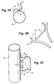
- FIG. 1 is a fragmentary plan view of a portion of a spacer and a water rod illustrating a pair of axially spaced tabs on the water rod for capturing the spacer and water rod together in accordance with the prior art;
- FIG. 2A is a schematic illustration of the orientation of a water rod and spacer clip showing the position of the water rod tab before assembly;
- FIG. 2B is an enlarged fragmentary cross-sectional view illustrating the clip and water rod tab prior to their assembly
- FIG. 2C is a perspective view illustrating the water rod tab and clip prior to assembly
- FIGS. 3A, 3B and 3 C are views substantially corresponding to FIGS. 2A, 2B and 2 C, respectively, illustrating the retention assembly after relative rotation of the spacer and water rod into an assembled condition;
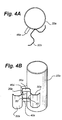
- FIG. 4A is a schematic illustration of relative portions of a water rod tab and spacer clip prior to assembly according to a second preferred embodiment of the present invention
- FIG. 4B is a perspective view of the water rod tab and spacer clip illustrated in FIG. 4A;
- FIG. 5A is a enlarged fragmentary cross-sectional view illustrating the position of the water rod tab, adjacent water rod and spacer clip after rotation and assembly;
- FIG. 5B is a view similar to FIG. 5A on a reduced scale illustrating in plan the position of the clip relative to the two water rods after assembly;
- FIG. 5C is a perspective view of the water rod tab fully assembled with the spacer clip and lying adjacent a second water rod.
- the spacer for use in a fuel bundle or assembly in a nuclear reactor, the spacer being generally designated 10 .
- the spacer includes a plurality of cylindrical ferrules 12 having stops 13 projecting from interior wall surfaces thereof and springs 16 for bearing against fuel rods 18 extending through the spacer in each of the ferrules 12 .
- the springs 16 impart a lateral force to the fuel rods to maintain the fuel rods in bearing engagement against the stops 13 .
- the spacer 10 also has a surrounding band 20 laterally encompassing the ferrules.
- a pair of water rods 22 pass through enlarged openings in the spacer 10 .
- a clip 24 is secured to the ferrules, for example, by welding, and has a vertical extent corresponding to the vertical extent of the ferrules.
- One of the water rods 22 carries upper and lower tabs 26 which engage upper and lower margins, respectively, of the clip 24 to prevent relative axial displacement of the spacer and one water rod.
- the twist of the water rods and spacers may be sufficient to misalign the tabs 26 with the clip, enabling the spacer and water rod for relative axial displacement.
- FIGS. 2 A- 2 C there is illustrated in a preferred form of the present invention, a spacer/water rod connecting structure or retention assembly, generally designated 30 , for use in a spacer of the type illustrated in FIG. 1 but having a different clip and water rod retention tab arrangement, as will now be explained.
- the clip 32 is generally U-shaped with laterally outwardly directed flanges 34 to facilitate welding to adjoining ferrules 12 (FIG. 1).
- the base of the U-shaped clip 32 defines a slot or opening 36 bounded by axially opposite structural portions 38 and 40 , as well as lateral or side structural portions 42 and 44 (FIG. 2B).
- the portions 38 , 40 , 42 and 44 perimetrically enclose the slot 36 .
- a clip tab 45 which projects toward the opposite side portion 44 of slot 36 .
- the metal material from which the clip 32 is made enables the clip tab 45 to be resiliently deflected.
- a water rod tab 46 projects generally radially outwardly from the water rod and is sized for reception in the slot 36 .
- the water rod is disposed through the opening in the spacer with the tab 46 outside of the opening or slot 36 as illustrated in FIG. 2B.
- the water rod tab 46 engages the tab 45 of the clip 32 , resiliently deflecting tab 45 such that the water rod tab 46 obtains the position illustrated in FIG. 3B within slot 36 .
- the clip tab 45 once the water rod tab 46 passes by out of engagement with tab 45 and into slot 36 , resiliently deforms back to its initial position, generally within the slot 36 .
- the side portion 44 of clip 32 and tab 45 lie on opposite sides of the water rod tab 46 , preventing relative rotation between the spacer and water rod. Even with a twist of an unchanneled fuel bundle assembly, the water rod tab 46 remains captured in the slot between the side portion 44 and clip tab 45 .
- a tool may be used to deflect the spring in the same direction as in the initial assembly whereby the tab 46 can be rotated out of the slot past the tab 45 .
- the water rod 22 a includes a tab 46 a.
- the clip 32 a includes a slot 36 a which is perimetrically bounded by axially opposite end portions 38 a and 40 a, as well as bounded on its sides by side portions 50 and 52 .
- the clip 32 a is secured to the spacer similarly as in the prior embodiment. In this form, however, the tab 45 projecting from one side portion of the clip is omitted.
- the tab 46 a is rotated into the slot 36 a by relative rotation of the spacer and water rod.
- the tab 46 a is thus prevented from rotational movement by one side portion 50 of the slot 36 a.
- a second water rod 23 is disposed through an opening in the spacer adjacent the first water rod. The second water rod prevents rotation of the tab out of the slot 36 a.
- the water rod does not rely on a square lower end plug and tie plate hole to prevent water rod rotation as in certain current designs.
- the present spacer/water rod retention assembly not only prevents relative rotation of the water rod and spacer to an extent permitting axial displacement of the water rod and spacer, particularly when installed in unchanneled fuel bundle assemblies, but also permits the less costly fabrication of a round water rod end plug and round openings in the lower tie plate of the fuel assembly.
Landscapes
- Physics & Mathematics (AREA)
- Engineering & Computer Science (AREA)
- Plasma & Fusion (AREA)
- General Engineering & Computer Science (AREA)
- High Energy & Nuclear Physics (AREA)
- Monitoring And Testing Of Nuclear Reactors (AREA)
Abstract
Description
- The present invention relates to apparatus and methods for axially and non-rotationally fixing one or more spacers and a water rod to one another in a nuclear fuel bundle assembly and particularly relates to spacer/water rod capture apparatus and methods for assembly and disassembly of the water rods and spacers.
- In boiling water nuclear reactors, fuel rods are grouped together in an essentially open-ended tubular flow channel, typically referred to as a fuel assembly or bundle. A plurality of fuel assemblies are positioned in the reactor core in a matrix and a coolant/moderator flows upwardly about the fuel rods for generating steam. The fuel rods are supported in each assembly between upper and lower tie plates. One or more water rods are usually located interiorly within each fuel rod bundle. Spacers are employed at predetermined elevations along each fuel bundle to restrain the fuel rods from bowing or vibrating during reactor operation.
- Typical spacers often include a plurality of ferrules arranged in side-by-side relation and secured, for example, by welding to one another to form a support matrix for the fuel rods. Generally, the role of the spacer in a fuel bundle assembly is to maintain the rods in fixed lateral locations relative to one another. These spacers are secured or captured in a manner preventing their movement relative to the longitudinal axis of the bundle during operation of the reactor. Conventional methods of maintaining the fuel rod spacers in position along the axis of the bundle include the use of a pair of tabs welded to the water rods engaging a spacer along its top and bottom, preventing axial movement of the spacer relative to the water rod in either axial direction. These spacers are assembled onto the water rod by relatively rotating the spacers and water rod such that the tabs pass through an opening in the spacer structure. The spacer is then rotated to an orientation such that part of the spacer structure is axially contacting one of the two tabs, the lower tab being preferred. In the assembled bundle, the water rod is typically prevented from rotation by a square lower end plug received in a square hole in the lower tie plate.
- There are, however, occasions where the fuel bundle is unchanneled. By unchanneled is meant that the fuel bundle assembly does not have the surrounding channel. For example, the bundles are unchanneled during initial fabrication when the spacers are secured to the water rod. Unchanneled bundles are relatively flexible with respect to torsion about the bundle axis. Thus, twist can occur in unchanneled bundles from normal handling of the bundles. If the twist is large enough, certain of the spacers, e.g., the upper spacers can be rotated to such an extent that the water rod tabs locate over and under the openings in the spacer structure used during assembly and no longer provide axial restraint. Also, for irradiated bundles where the friction forces between the spacer springs and the rod is significantly reduced, the spacers can become axially displaced from their proper location. Further, current designs employ square water rod lower end plugs and square lower tie plate holes to maintain angular orientation of the water rod tab relative to the spacer structure. Such end plugs and holes are costly as compared with round end plugs and holes.
- In accordance with the present invention, a spacer and water rod retention or capture assembly is provided in which a single tab on the water rod is captured by spacer structure, preventing relative axial displacement of the spacer and water rod, notwithstanding twisting of the fuel bundle, particularly in the unchanneled configuration. The retention assembly prevents the rotation of the water rod and the tab carried thereby relative to the spacer to the extent the water rod tab cannot be aligned with an opening in the spacer which would otherwise permit relative axial displacement of the spacer and water rod.
- In a first preferred embodiment of the present invention, the spacer includes a spacer structure or clip having a central opening bounded perimetrically on axially opposite ends and laterally by opposite side portions. One side portion of the clip includes a tab projecting generally toward the opposite side portion and which tab is resiliently mounted, delimiting the slot opening. The clip, of course, is welded or otherwise secured to the spacer and the slot lies adjacent the water rod position in a plane angularly related to the water rod. Upon locating the water rod in the spacer, the water rod and spacer are relatively rotated such that the water rod tab engages and resiliently displaces the clip tab enabling the water rod tab to pass the clip tab into the slot. The clip tab then resiliently reverts to its original shape. The interference with the resilient tab, together with the obtuse angle of approach of the water rod tab to the clip tab, prevents disengagement of the water rod tab from the spacer. To disassemble the spacer and water rod, a tool can be inserted to deflect the clip tab in the same direction as it is deflected in the initial assembly by the water rod tab whereby the water rod tab can be rotated out of the slot freeing the water rod and clip for relative axial movement.
- In a second preferred embodiment of the present invention, the water rod tab is rotated into a slot in the spacer structure whereby one side edge of the slot forms a limit stop for the tab. The water rod tab is prevented from rotating out of the slot by the installation of a second water rod adjacent the first water rod. In the first embodiment, the water rod tab is restrained from rotation by its fit-up with the slot of the spacer clip and in the second embodiment by the spacer clip and an adjoining water rod. In both embodiments, reliance on a square lower end plug and correspondingly shaped tie plate hole to prevent water rod rotation as in certain current spacer/water rod retention assemblies is entirely avoided.
- In a preferred embodiment according to the present invention, there is provided in a nuclear fuel bundle having a plurality of generally parallel, axially extending fuel rods, a plurality of spacers axially spaced from one another for maintaining the fuel rods spaced laterally from one another, and a pair of water rods extending in generally side-by-side parallel relation to the fuel rods and passing through the spacers, a spacer and water rod retention assembly, comprising a water rod connecting structure carried by one of the spacers and having a slot bounded by opposite structure portions spaced in an axial direction from one another and a pair of oppositely disposed side structure portions between the axially opposite portions perimetrically enclosing the slot, the slot substantially spanning between the water rods, one of the water rods having a tab projecting laterally outwardly thereof and into the slot, the tab having an axial extent engaging the axially opposite structure portions to limit relative axial movement of the one spacer and the one water rod, another of the water rods and one of the side structure portions confining the water rod tab in the slot precluding substantial relative rotational movement between the one spacer and the one water rod.
- In a further preferred embodiment according to the present invention, there is provided in a nuclear fuel bundle having a plurality of generally parallel, axially extending fuel rods, a plurality of spacers axially spaced from one another for maintaining the fuel rods spaced laterally from one another, and a pair of water rods extending in generally side-by-side parallel relation to the fuel rods and passing through the spacers, a spacer and water rod retention assembly, comprising a water rod connecting structure carried by one of the spacers and having a slot bounded by opposite end portions spaced in an axial direction from one another and at least one side portion between the axially opposite end portions, the slot substantially spanning between the water rods, one of the water rods having a tab projecting laterally outwardly thereof and into the slot, the tab having an axial extent engageable with the axially opposite end portions to limit relative axial movement of the one spacer and the one water rod, another of the water rods and the one side portion confining the water rod tab in the slot precluding substantial relative rotational movement between the one spacer and the one water rod.
- In a further preferred embodiment according to the present invention, there is provided in a nuclear fuel bundle having a plurality of spacers for maintaining fuel rods spaced one from the other and a pair of water rods extending axially and generally perpendicular to and through the spacers, a method of retaining the spacer on one of the water rods, comprising the steps of relatively rotating one of the water rods and one of the spacers to dispose a tab projecting laterally outwardly of the one water rod into a slot carried by a clip on the one spacer, providing a stop along one side of the slot of the clip to preclude continued rotation of the tab and clip relative to one another and installing another of the water rods adjacent the one water rod and adjacent the clip to preclude relative rotation of the one water rod and the spacer in a direction removing the tab from the slot whereby relative movement of the one spacer and the one water rod in opposite axial directions and substantial relative rotational movement between the one water rod and the one spacer are precluded.
- FIG. 1 is a fragmentary plan view of a portion of a spacer and a water rod illustrating a pair of axially spaced tabs on the water rod for capturing the spacer and water rod together in accordance with the prior art;
- FIG. 2A is a schematic illustration of the orientation of a water rod and spacer clip showing the position of the water rod tab before assembly;
- FIG. 2B is an enlarged fragmentary cross-sectional view illustrating the clip and water rod tab prior to their assembly;
- FIG. 2C is a perspective view illustrating the water rod tab and clip prior to assembly;
- FIGS. 3A, 3B and 3C are views substantially corresponding to FIGS. 2A, 2B and 2C, respectively, illustrating the retention assembly after relative rotation of the spacer and water rod into an assembled condition;
- FIG. 4A is a schematic illustration of relative portions of a water rod tab and spacer clip prior to assembly according to a second preferred embodiment of the present invention;
- FIG. 4B is a perspective view of the water rod tab and spacer clip illustrated in FIG. 4A;
- FIG. 5A is a enlarged fragmentary cross-sectional view illustrating the position of the water rod tab, adjacent water rod and spacer clip after rotation and assembly;
- FIG. 5B is a view similar to FIG. 5A on a reduced scale illustrating in plan the position of the clip relative to the two water rods after assembly; and
- FIG. 5C is a perspective view of the water rod tab fully assembled with the spacer clip and lying adjacent a second water rod.
- Referring now to the drawings, particularly to FIG. 1, there is illustrated a spacer for use in a fuel bundle or assembly in a nuclear reactor, the spacer being generally designated 10. The spacer includes a plurality of
cylindrical ferrules 12 havingstops 13 projecting from interior wall surfaces thereof and springs 16 for bearing against fuel rods 18 extending through the spacer in each of theferrules 12. Thesprings 16 impart a lateral force to the fuel rods to maintain the fuel rods in bearing engagement against thestops 13. Thespacer 10 also has a surroundingband 20 laterally encompassing the ferrules. - As illustrated, a pair of
water rods 22 pass through enlarged openings in thespacer 10. Aclip 24 is secured to the ferrules, for example, by welding, and has a vertical extent corresponding to the vertical extent of the ferrules. One of thewater rods 22 carries upper andlower tabs 26 which engage upper and lower margins, respectively, of theclip 24 to prevent relative axial displacement of the spacer and one water rod. As previously stated, in unchanneled bundles, the twist of the water rods and spacers may be sufficient to misalign thetabs 26 with the clip, enabling the spacer and water rod for relative axial displacement. - Referring to FIGS. 2A-2C, there is illustrated in a preferred form of the present invention, a spacer/water rod connecting structure or retention assembly, generally designated 30, for use in a spacer of the type illustrated in FIG. 1 but having a different clip and water rod retention tab arrangement, as will now be explained. As best illustrated in FIG. 2C, the
clip 32 is generally U-shaped with laterally outwardly directedflanges 34 to facilitate welding to adjoining ferrules 12 (FIG. 1). The base of theU-shaped clip 32 defines a slot oropening 36 bounded by axially oppositestructural portions structural portions 42 and 44 (FIG. 2B). Thus, theportions slot 36. - Along the
side portion 42 ofclip 32, there is provided aclip tab 45 which projects toward the opposite side portion 44 ofslot 36. The metal material from which theclip 32 is made enables theclip tab 45 to be resiliently deflected. Awater rod tab 46 projects generally radially outwardly from the water rod and is sized for reception in theslot 36. - To secure the spacer and water rod relative to one another, the water rod is disposed through the opening in the spacer with the
tab 46 outside of the opening orslot 36 as illustrated in FIG. 2B. By rotating the spacer and water rod relative to one another, for example, by rotating the water rod in a counterclockwise direction as illustrated in FIG. 2B, thewater rod tab 46 engages thetab 45 of theclip 32, resiliently deflectingtab 45 such that thewater rod tab 46 obtains the position illustrated in FIG. 3B withinslot 36. Theclip tab 45, once thewater rod tab 46 passes by out of engagement withtab 45 and intoslot 36, resiliently deforms back to its initial position, generally within theslot 36. As a consequence, the side portion 44 ofclip 32 andtab 45 lie on opposite sides of thewater rod tab 46, preventing relative rotation between the spacer and water rod. Even with a twist of an unchanneled fuel bundle assembly, thewater rod tab 46 remains captured in the slot between the side portion 44 andclip tab 45. To disassemble the water rod and spacer, a tool, not shown, may be used to deflect the spring in the same direction as in the initial assembly whereby thetab 46 can be rotated out of the slot past thetab 45. - Referring now to the embodiment of the present invention illustrated in FIGS. 4A-4B and 5A-5C, wherein like reference numerals as in the prior embodiment apply to like parts followed by suffix “a,” the
water rod 22 a includes atab 46 a. Theclip 32 a includes aslot 36 a which is perimetrically bounded by axiallyopposite end portions side portions clip 32 a is secured to the spacer similarly as in the prior embodiment. In this form, however, thetab 45 projecting from one side portion of the clip is omitted. - To secure the spacer and one water rod against axial displacement relative to one another, the
tab 46 a is rotated into theslot 36 a by relative rotation of the spacer and water rod. Thetab 46 a is thus prevented from rotational movement by oneside portion 50 of theslot 36 a. To prevent rotational movement of the tab in a direction displacing the tab from the slot, asecond water rod 23 is disposed through an opening in the spacer adjacent the first water rod. The second water rod prevents rotation of the tab out of theslot 36 a. The water rod does not rely on a square lower end plug and tie plate hole to prevent water rod rotation as in certain current designs. Thus, the present spacer/water rod retention assembly not only prevents relative rotation of the water rod and spacer to an extent permitting axial displacement of the water rod and spacer, particularly when installed in unchanneled fuel bundle assemblies, but also permits the less costly fabrication of a round water rod end plug and round openings in the lower tie plate of the fuel assembly. - While the invention has been described in connection with what is presently considered to be the most practical and preferred embodiment, it is to be understood that the invention is not to be limited to the disclosed embodiment, but on the contrary, is intended to cover various modifications and equivalent arrangements included within the spirit and scope of the appended claims.
Claims (5)
Priority Applications (1)
| Application Number | Priority Date | Filing Date | Title |
|---|---|---|---|
| US10/119,293 US6735268B2 (en) | 2002-04-10 | 2002-04-10 | Fuel spacer/water rod capture apparatus and methods for boiling water nuclear reactors |
Applications Claiming Priority (1)
| Application Number | Priority Date | Filing Date | Title |
|---|---|---|---|
| US10/119,293 US6735268B2 (en) | 2002-04-10 | 2002-04-10 | Fuel spacer/water rod capture apparatus and methods for boiling water nuclear reactors |
Publications (2)
| Publication Number | Publication Date |
|---|---|
| US20030194045A1 true US20030194045A1 (en) | 2003-10-16 |
| US6735268B2 US6735268B2 (en) | 2004-05-11 |
Family
ID=28789919
Family Applications (1)
| Application Number | Title | Priority Date | Filing Date |
|---|---|---|---|
| US10/119,293 Expired - Lifetime US6735268B2 (en) | 2002-04-10 | 2002-04-10 | Fuel spacer/water rod capture apparatus and methods for boiling water nuclear reactors |
Country Status (1)
| Country | Link |
|---|---|
| US (1) | US6735268B2 (en) |
Cited By (1)
| Publication number | Priority date | Publication date | Assignee | Title |
|---|---|---|---|---|
| US20130272479A1 (en) * | 2012-04-17 | 2013-10-17 | Jeffrey T Lee | Lower end fitting for nuclear fuel assembly made from intersecting metal strips |
Family Cites Families (12)
| Publication number | Priority date | Publication date | Assignee | Title |
|---|---|---|---|---|
| DE2214457A1 (en) * | 1972-03-24 | 1973-10-04 | Siemens Ag | NUCLEAR REACTOR WITH A SPACER FOR FUEL ROD |
| JPS5910880A (en) | 1982-07-09 | 1984-01-20 | 株式会社日立製作所 | Fuel spacer |
| US4508679A (en) * | 1982-08-20 | 1985-04-02 | General Electric Company | Nuclear fuel assembly spacer |
| JPS6196491A (en) | 1984-10-17 | 1986-05-15 | 株式会社日立製作所 | Fuel spacer |
| US4876063A (en) * | 1988-03-17 | 1989-10-24 | General Electric Company | Double-d water rod for 9 by 9 fuel bundle |
| JPH0636046B2 (en) | 1988-06-08 | 1994-05-11 | 株式会社日立製作所 | Fuel assemblies, fuel spacers, and initial reactor core of reactor |
| US5085827A (en) | 1989-12-27 | 1992-02-04 | General Electric Company | Nuclear fuel assembly spacer and loop spring with enhanced flexibility |
| US5002726A (en) | 1989-12-27 | 1991-03-26 | General Electric Company | Nuclear fuel assembly spacer and loop spring with enhanced flexibility |
| US5173252A (en) | 1991-05-17 | 1992-12-22 | General Electric Company | Removable springs for ferrule spacer |
| JP3095311B2 (en) | 1993-05-25 | 2000-10-03 | 株式会社日立製作所 | Fuel assembly |
| US5727039A (en) | 1996-03-19 | 1998-03-10 | General Electric Company | Spacer capture mechansim for non-round water rods |
| US6285729B1 (en) | 1999-05-07 | 2001-09-04 | General Electric Company | Fuel spacer/water rod capture apparatus and methods for boiling water nuclear reactors |
-
2002
- 2002-04-10 US US10/119,293 patent/US6735268B2/en not_active Expired - Lifetime
Cited By (1)
| Publication number | Priority date | Publication date | Assignee | Title |
|---|---|---|---|---|
| US20130272479A1 (en) * | 2012-04-17 | 2013-10-17 | Jeffrey T Lee | Lower end fitting for nuclear fuel assembly made from intersecting metal strips |
Also Published As
| Publication number | Publication date |
|---|---|
| US6735268B2 (en) | 2004-05-11 |
Similar Documents
| Publication | Publication Date | Title |
|---|---|---|
| US4312705A (en) | Spacer for nuclear reactor fuel assemblies | |
| JPS61139790A (en) | Fuel assembly debris trap | |
| US4081324A (en) | Spacer capture rod to spacer grid attachment device | |
| EP0175496B1 (en) | Grid spacer capture device for nuclear fuel assembly | |
| US5675621A (en) | Reduced height flat spring spacer for nuclear fuel rods | |
| JP4102869B2 (en) | Integral fastening spacer for nuclear reactor grid and associated method | |
| EP0797217B1 (en) | Spacer capture mechanism for non-round water rods | |
| US6285729B1 (en) | Fuel spacer/water rod capture apparatus and methods for boiling water nuclear reactors | |
| US5566217A (en) | Reduced height spacer for nuclear fuel rods | |
| JPS58186082A (en) | Fuel assembly | |
| US6735268B2 (en) | Fuel spacer/water rod capture apparatus and methods for boiling water nuclear reactors | |
| US8571168B2 (en) | Fuel element for a light water reactor, and method for repairing the fuel element | |
| US5875224A (en) | Swirler attachment for a spacer of a nuclear fuel bundle | |
| US5553108A (en) | Water rod attachment in a nuclear reactor fuel bundle | |
| JPH1039068A (en) | Spacer for reactor fuel assembly | |
| US5815545A (en) | Nuclear fuel assembly spacer and spring | |
| US5671261A (en) | Method and apparatus for attaching a lifting bar to a load bearing water rod in a nuclear fuel assembly | |
| US5669729A (en) | Reconstitutable rod cluster control assembly | |
| JPH05164865A (en) | Fuel assembly | |
| EP0895248A1 (en) | System for joining the bottom head, independent dashpot and reinforced guide tubes in nuclear reactor fuel elements | |
| US20230386687A1 (en) | Fuel Assembly | |
| JPH0784081A (en) | Support grid for nuclear reactor fuel assemblies | |
| JPH0539516Y2 (en) | ||
| JPH0312588A (en) | Fuel assembly | |
| JPS6350788A (en) | Fuel aggregate |
Legal Events
| Date | Code | Title | Description |
|---|---|---|---|
| AS | Assignment |
Owner name: GENERAL ELECTRIC COMPANY, NEW YORK Free format text: ASSIGNMENT OF ASSIGNORS INTEREST;ASSIGNORS:HIGGINS, RUSSELL P.;SMITH, DAVID G.;REEL/FRAME:013192/0196 Effective date: 20020724 |
|
| FEPP | Fee payment procedure |
Free format text: PAYOR NUMBER ASSIGNED (ORIGINAL EVENT CODE: ASPN); ENTITY STATUS OF PATENT OWNER: LARGE ENTITY |
|
| STCF | Information on status: patent grant |
Free format text: PATENTED CASE |
|
| CC | Certificate of correction | ||
| FPAY | Fee payment |
Year of fee payment: 4 |
|
| FPAY | Fee payment |
Year of fee payment: 8 |
|
| REMI | Maintenance fee reminder mailed | ||
| FPAY | Fee payment |
Year of fee payment: 12 |
|
| SULP | Surcharge for late payment |
Year of fee payment: 11 |