US20030193879A1 - Suspension device - Google Patents
Suspension device Download PDFInfo
- Publication number
- US20030193879A1 US20030193879A1 US10/284,000 US28400002A US2003193879A1 US 20030193879 A1 US20030193879 A1 US 20030193879A1 US 28400002 A US28400002 A US 28400002A US 2003193879 A1 US2003193879 A1 US 2003193879A1
- Authority
- US
- United States
- Prior art keywords
- traverse
- disposed
- weighted end
- storage device
- media storage
- Prior art date
- Legal status (The legal status is an assumption and is not a legal conclusion. Google has not performed a legal analysis and makes no representation as to the accuracy of the status listed.)
- Abandoned
Links
- 239000000725 suspension Substances 0.000 title claims abstract description 30
- 230000003287 optical effect Effects 0.000 claims abstract description 37
- 238000012986 modification Methods 0.000 description 2
- 230000004048 modification Effects 0.000 description 2
- 230000001133 acceleration Effects 0.000 description 1
- 238000013459 approach Methods 0.000 description 1
- 238000010586 diagram Methods 0.000 description 1
- 230000035939 shock Effects 0.000 description 1
Images


Classifications
-
- G—PHYSICS
- G11—INFORMATION STORAGE
- G11B—INFORMATION STORAGE BASED ON RELATIVE MOVEMENT BETWEEN RECORD CARRIER AND TRANSDUCER
- G11B33/00—Constructional parts, details or accessories not provided for in the other groups of this subclass
- G11B33/02—Cabinets; Cases; Stands; Disposition of apparatus therein or thereon
- G11B33/08—Insulation or absorption of undesired vibrations or sounds
-
- G—PHYSICS
- G11—INFORMATION STORAGE
- G11B—INFORMATION STORAGE BASED ON RELATIVE MOVEMENT BETWEEN RECORD CARRIER AND TRANSDUCER
- G11B17/00—Guiding record carriers not specifically of filamentary or web form, or of supports therefor
- G11B17/02—Details
- G11B17/022—Positioning or locking of single discs
- G11B17/028—Positioning or locking of single discs of discs rotating during transducing operation
Definitions
- the present invention relates to a suspension device for an optical media storage device, and in particular to a suspension device reducing vibration caused by the optical media storage device.
- an optical media storage device such as an optical disk drive
- a loader is composed of a loader, a traverse, a dynamic mass and a spindle motor.
- the spindle motor is disposed on the traverse.
- the dynamic mass balances and eliminates vibration caused by rotation of the spindle motor.
- multiple isolators are disposed between the traverse and the loader and multiple dampers are disposed between the traverse and the dynamic mass for absorbing shock. Nevertheless, the positions of the mass centers of the conventional dynamic mass and traverse are not optimum. Also, the arrangement of the isolators and dampers is not optimum.
- FIG. 1 is a schematic view showing a conventional suspension device 1 of an optical disk drive.
- the mass centers of the dynamic mass 11 and the traverse 12 are close to the middle of the suspension device 1 . Because of this arrangement of the suspension device 1 , the measured vibration values of the suspension device 1 fluctuate drastically in different directions.
- FIG. 2 is a schematic view showing another conventional suspension device 2 of an optical disk drive.
- the dynamic mass 21 is disposed between the traverse 22 and the loader 23 .
- the damper 24 is disposed between the traverse 22 and the dynamic mass 21 .
- the isolator 25 is disposed between the traverse 22 and the loader 23 . This arrangement only changes the positions of the damper 24 and the isolator 25 .
- the mass center of the traverse 22 is still close to the middle of the suspension device 2 .
- the measured vibration values of the suspension device 2 also fluctuate drastically in different directions.
- the invention provides a suspension device reducing vibration effectively.
- the positions of the mass centers of the dynamic mass and the traverse are adjusted simultaneously. Meanwhile, the positions of the isolators and dampers are adjusted.
- vibration caused by the optical media storage device is reduced tremendously.
- An object of the invention is to provide a suspension device for an optical media storage device having a spindle motor.
- the suspension device comprises a loader, a traverse and a dynamic mass.
- the traverse is disposed on the loader and has a first weighted end.
- the mass center of the traverse is on the first weighted end and the spindle motor is disposed on the first weighted end.
- the dynamic mass is disposed on the traverse and has a second weighted end.
- the mass center of the dynamic mass is on the second weighted end and the second weighted end is located above the first weighted end.
- the optical media storage device is an optical disk drive.
- a plurality of isolators are disposed between the traverse and the loader, and the plurality of isolators are disposed close to the corners of the traverse.
- a plurality of dampers are disposed between the dynamic mass and the traverse, and the plurality of dampers are disposed close to the positions of the isolators.
- FIG. 1 is a schematic view showing a conventional suspension device of an optical disk drive
- FIG. 2 is a schematic view showing another conventional suspension device of an optical disk drive
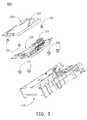
- FIG. 3 is a perspective exploded view showing the suspension device of the invention.
- FIG. 4 is a top view showing an optical disk drive having the suspension device of the invention.
- FIG. 5 is a cross section taken along line A-A of FIG. 4;
- FIG. 6 is a schematic view according to FIG. 5;
- FIG. 7 is a diagram showing vibration curves of the present suspension device when the mass center of the dynamic mass is in different positions.
- the suspension device 100 for an optical media storage device comprises a loader 110 , a traverse 120 and a dynamic mass 130 .
- the traverse 120 is disposed on the loader 110 and four isolators 122 are disposed between the traverse 120 and the loader 110 .
- the dynamic mass 130 is disposed on the traverse 120 and four dampers 132 are disposed between the dynamic mass 130 and the traverse 120 .
- a spindle motor 124 two parallel sliding tracks 126 , an optical pick-up 128 and a DC servo motor 129 are disposed on the traverse 120 .
- the traverse 120 has a first weighted end 121 .
- the weight of the traverse 120 is not uniformly distributed over the traverse 120 .
- the first weighted end 121 dominates major weight while the other end of the traverse 120 dominates minor weight.
- the mass center of the traverse 120 is close to the first weighted end 121 .
- the spindle motor 124 is disposed on the first weighted end 121 .
- the dynamic mass 130 has a second weighted end 131 .
- the weight of the dynamic mass 130 is not uniformly distributed over the dynamic mass 130 .
- the second weighted end 131 dominates major weight while the other end of the dynamic mass 130 dominates minor weight.
- the mass center of the dynamic mass 130 is close to the second weighted end 131 .
- the second weighted end 131 is located above the first weighted end 121 .
- vibration values generated by the spindle motor are measured and illustrated in FIG. 7.
- X axis denotes rotation of the spindle motor (rpm)
- curve A represents that the mass center of the dynamic mass is far from the weighted end
- curve B represents that the mass center of the dynamic mass is on the middle of the dynamic mass
- curve C represents that the mass center of the dynamic mass is on the weighted end
- Y axis denotes front and rear vibration accelerations (G) of the suspension device.
- the suspension device 100 uses the dynamic mass 130 whose mass center is close to the second weighted end 131 (front end).
- the vibration caused by the spindle motor 124 is reduced or eliminated effectively.
Landscapes
- Vibration Prevention Devices (AREA)
Abstract
A suspension device for an optical media storage device having a spindle motor. The suspension device includes a loader, a traverse and a dynamic mass. The traverse is disposed on the loader and has a first weighted end. The mass center of the traverse is on the first weighted end and the spindle motor is disposed on the first weighted end. The dynamic mass is disposed on the traverse and has a second weighted end. The mass center of the dynamic mass is on the second weighted end and the second weighted end is located above the first weighted end. Thus, when the spindle motor operates, the vibration of the optical media storage device is reduced tremendously.
Description
- 1. Field of the Invention
- The present invention relates to a suspension device for an optical media storage device, and in particular to a suspension device reducing vibration caused by the optical media storage device.
- 2. Description of the Related Art
- Generally speaking, an optical media storage device, such as an optical disk drive, is composed of a loader, a traverse, a dynamic mass and a spindle motor. The spindle motor is disposed on the traverse. The dynamic mass balances and eliminates vibration caused by rotation of the spindle motor. In addition, multiple isolators are disposed between the traverse and the loader and multiple dampers are disposed between the traverse and the dynamic mass for absorbing shock. Nevertheless, the positions of the mass centers of the conventional dynamic mass and traverse are not optimum. Also, the arrangement of the isolators and dampers is not optimum.
- FIG. 1 is a schematic view showing a
conventional suspension device 1 of an optical disk drive. The mass centers of thedynamic mass 11 and thetraverse 12 are close to the middle of thesuspension device 1. Because of this arrangement of thesuspension device 1, the measured vibration values of thesuspension device 1 fluctuate drastically in different directions. - FIG. 2 is a schematic view showing another
conventional suspension device 2 of an optical disk drive. Thedynamic mass 21 is disposed between thetraverse 22 and theloader 23. Thedamper 24 is disposed between thetraverse 22 and thedynamic mass 21. Theisolator 25 is disposed between thetraverse 22 and theloader 23. This arrangement only changes the positions of thedamper 24 and theisolator 25. The mass center of thetraverse 22 is still close to the middle of thesuspension device 2. Thus, the measured vibration values of thesuspension device 2 also fluctuate drastically in different directions. - Consequently, the invention provides a suspension device reducing vibration effectively. The positions of the mass centers of the dynamic mass and the traverse are adjusted simultaneously. Meanwhile, the positions of the isolators and dampers are adjusted. Thus, vibration caused by the optical media storage device is reduced tremendously.
- An object of the invention is to provide a suspension device for an optical media storage device having a spindle motor. The suspension device comprises a loader, a traverse and a dynamic mass. The traverse is disposed on the loader and has a first weighted end. The mass center of the traverse is on the first weighted end and the spindle motor is disposed on the first weighted end. The dynamic mass is disposed on the traverse and has a second weighted end. The mass center of the dynamic mass is on the second weighted end and the second weighted end is located above the first weighted end. Thus, when the spindle motor operates, the vibration of the suspension device is reduced tremendously.
- Preferably, the optical media storage device is an optical disk drive.
- Preferably, a plurality of isolators are disposed between the traverse and the loader, and the plurality of isolators are disposed close to the corners of the traverse.
- Preferably, a plurality of dampers are disposed between the dynamic mass and the traverse, and the plurality of dampers are disposed close to the positions of the isolators.
- A detailed description is given in the following embodiments with reference to the accompanying drawings.
- The present invention can be more fully understood by reading the subsequent detailed description and examples with references made to the accompanying drawings, wherein:
- FIG. 1 is a schematic view showing a conventional suspension device of an optical disk drive;
- FIG. 2 is a schematic view showing another conventional suspension device of an optical disk drive;
- FIG. 3 is a perspective exploded view showing the suspension device of the invention;
- FIG. 4 is a top view showing an optical disk drive having the suspension device of the invention;
- FIG. 5 is a cross section taken along line A-A of FIG. 4;
- FIG. 6 is a schematic view according to FIG. 5; and
- FIG. 7 is a diagram showing vibration curves of the present suspension device when the mass center of the dynamic mass is in different positions.
- Referring to FIG. 3 and FIG. 4, the
suspension device 100 for an optical media storage device comprises aloader 110, atraverse 120 and adynamic mass 130. Thetraverse 120 is disposed on theloader 110 and fourisolators 122 are disposed between thetraverse 120 and theloader 110. Thedynamic mass 130 is disposed on thetraverse 120 and fourdampers 132 are disposed between thedynamic mass 130 and thetraverse 120. Additionally, aspindle motor 124, two parallel slidingtracks 126, an optical pick-up 128 and aDC servo motor 129 are disposed on thetraverse 120. - Referring to FIG. 4, FIG. 5 and FIG. 6, the
traverse 120 has a first weightedend 121. The weight of thetraverse 120 is not uniformly distributed over thetraverse 120. The first weightedend 121 dominates major weight while the other end of thetraverse 120 dominates minor weight. Thus, the mass center of thetraverse 120 is close to the first weightedend 121. Meanwhile, thespindle motor 124 is disposed on the first weightedend 121. Similarly, thedynamic mass 130 has a second weightedend 131. The weight of thedynamic mass 130 is not uniformly distributed over thedynamic mass 130. The second weightedend 131 dominates major weight while the other end of thedynamic mass 130 dominates minor weight. Thus, the mass center of thedynamic mass 130 is close to the second weightedend 131. Specifically, the second weightedend 131 is located above the first weightedend 121. - In order to demonstrate that the
present suspension device 100 can effectively reduce vibration caused by the optical media storage device, vibration values generated by the spindle motor are measured and illustrated in FIG. 7. As shown in FIG. 7, X axis denotes rotation of the spindle motor (rpm), curve A represents that the mass center of the dynamic mass is far from the weighted end, curve B represents that the mass center of the dynamic mass is on the middle of the dynamic mass, curve C represents that the mass center of the dynamic mass is on the weighted end, and Y axis denotes front and rear vibration accelerations (G) of the suspension device. - As shown in FIG. 7, when the rotation of the spindle motor is below 7000 rpm and the mass center of the dynamic mass approaches the weighted end (front end), the vibration value becomes increasingly smaller (curve C).
- Accordingly, the
suspension device 100 uses thedynamic mass 130 whose mass center is close to the second weighted end 131 (front end). Thus, the vibration caused by thespindle motor 124 is reduced or eliminated effectively. - While the invention has been described by way of examples and in terms of the preferred embodiments, it is to be understood that the invention is not limited to the disclosed embodiments. To the contrary, it is intended to cover various modifications and similar arrangements (as would be apparent to those skilled in the art). Therefore, the scope of the appended claims should be accorded the broadest interpretation so as to encompass all such modifications and similar arrangements.
Claims (13)
1. A suspension device for an optical media storage device having a spindle motor, comprising:
a loader;
a traverse disposed on the loader and having a first weighted end, wherein the mass center of the traverse is on the first weighted end and the spindle motor is disposed on the first weighted end; and
a dynamic mass disposed on the traverse and having a second weighted end, wherein the mass center of the dynamic mass is on the second weighted end and the second weighted end is located above the first weighted end,
whereby, when the spindle motor operates, the vibration of the suspension device is reduced tremendously.
2. The suspension device as claimed in claim 1 , wherein the optical media storage device is an optical disk drive.
3. The suspension device as claimed in claim 1 , wherein a plurality of isolators are disposed between the traverse and the loader, and the plurality of isolators are disposed close to the corners of the traverse.
4. The suspension device as claimed in claim 1 , wherein a plurality of dampers are disposed between the dynamic mass and the traverse, and the plurality of dampers are disposed close to the positions of the isolators.
5. An optical media storage device, comprising:
a loader;
a traverse disposed on the loader and having a first weighted end, wherein the mass center of the traverse is on the first weighted end;
a dynamic mass disposed on the traverse and having a second weighted end, wherein the mass center of the dynamic mass is on the second weighted end and the second weighted end is located above the first weighted end;
a spindle motor disposed on the first weighted end of the traverse;
an optical pick-up; and
a driving motor disposed on the traverse to drive the optical pick-up.
6. The optical media storage device as claimed in claim 5 , further comprising two parallel sliding tracks, wherein one end of each sliding track is fixed to the first weighted end of the traverse while the other end is fixed to the opposite end of the first weighted end.
7. The optical media storage device as claimed in claim 6 , wherein the optical pick-up slides on the two parallel sliding tracks.
8. The optical media storage device as claimed in claim 5 , further comprising a driving gear set connected to the optical pick-up and the driving motor, wherein the driving motor drives the optical pick-up to slide on the two parallel sliding tracks by the driving gear set.
9. The optical media storage device as claimed in claim 5 , wherein the optical media storage device is an optical disk drive.
10. The optical media storage device as claimed in claim 5 , wherein a plurality of isolators are disposed between the traverse and the loader, and the plurality of isolators are disposed close to the corners of the traverse.
11. The optical media storage device as claimed in claim 5 , wherein a plurality of dampers are disposed between the dynamic mass and the traverse, and the plurality of dampers are disposed close to the positions of the isolators.
12. The optical media storage device as claimed in claim 5 , wherein the driving motor is a DC servo motor.
13. The optical media storage device as claimed in claim 5 , wherein the driving motor is a stepping motor.
Applications Claiming Priority (2)
| Application Number | Priority Date | Filing Date | Title |
|---|---|---|---|
| TW91204857 | 2002-04-12 | ||
| TW091204857U TW540793U (en) | 2002-04-12 | 2002-04-12 | Suspension device |
Publications (1)
| Publication Number | Publication Date |
|---|---|
| US20030193879A1 true US20030193879A1 (en) | 2003-10-16 |
Family
ID=28788992
Family Applications (1)
| Application Number | Title | Priority Date | Filing Date |
|---|---|---|---|
| US10/284,000 Abandoned US20030193879A1 (en) | 2002-04-12 | 2002-10-30 | Suspension device |
Country Status (2)
| Country | Link |
|---|---|
| US (1) | US20030193879A1 (en) |
| TW (1) | TW540793U (en) |
Cited By (2)
| Publication number | Priority date | Publication date | Assignee | Title |
|---|---|---|---|---|
| US20050216927A1 (en) * | 2004-03-22 | 2005-09-29 | Pioneer Corporation | Disk driving apparatus |
| US20080137228A1 (en) * | 2005-08-30 | 2008-06-12 | Fujitsu Limited | Magnetic disc drive |
Citations (5)
| Publication number | Priority date | Publication date | Assignee | Title |
|---|---|---|---|---|
| US4325133A (en) * | 1979-03-12 | 1982-04-13 | Gustav Reitmayer | Disc player apparatus |
| US4922478A (en) * | 1987-04-24 | 1990-05-01 | U.S. Philips Corporation | Device for supporting a sub-frame of a disc record player on a frame, and disc record player comprising such a device |
| US5101399A (en) * | 1987-11-05 | 1992-03-31 | Mitsubishi Denki Kabushiki Kaisha | Deck base locking device for recording playback unit |
| US6366552B1 (en) * | 1998-05-15 | 2002-04-02 | Deutsche Thomson-Brandt Gmbh | Disk drive with compensation of disk eccentricity |
| US6741544B1 (en) * | 1997-09-25 | 2004-05-25 | Matsushita Electric Industrial Co., Ltd. | Disk drive apparatus |
-
2002
- 2002-04-12 TW TW091204857U patent/TW540793U/en not_active IP Right Cessation
- 2002-10-30 US US10/284,000 patent/US20030193879A1/en not_active Abandoned
Patent Citations (5)
| Publication number | Priority date | Publication date | Assignee | Title |
|---|---|---|---|---|
| US4325133A (en) * | 1979-03-12 | 1982-04-13 | Gustav Reitmayer | Disc player apparatus |
| US4922478A (en) * | 1987-04-24 | 1990-05-01 | U.S. Philips Corporation | Device for supporting a sub-frame of a disc record player on a frame, and disc record player comprising such a device |
| US5101399A (en) * | 1987-11-05 | 1992-03-31 | Mitsubishi Denki Kabushiki Kaisha | Deck base locking device for recording playback unit |
| US6741544B1 (en) * | 1997-09-25 | 2004-05-25 | Matsushita Electric Industrial Co., Ltd. | Disk drive apparatus |
| US6366552B1 (en) * | 1998-05-15 | 2002-04-02 | Deutsche Thomson-Brandt Gmbh | Disk drive with compensation of disk eccentricity |
Cited By (3)
| Publication number | Priority date | Publication date | Assignee | Title |
|---|---|---|---|---|
| US20050216927A1 (en) * | 2004-03-22 | 2005-09-29 | Pioneer Corporation | Disk driving apparatus |
| US7260821B2 (en) * | 2004-03-22 | 2007-08-21 | Pioneer Corporation | Disk driving apparatus |
| US20080137228A1 (en) * | 2005-08-30 | 2008-06-12 | Fujitsu Limited | Magnetic disc drive |
Also Published As
| Publication number | Publication date |
|---|---|
| TW540793U (en) | 2003-07-01 |
Similar Documents
| Publication | Publication Date | Title |
|---|---|---|
| US6883175B2 (en) | Dynamic vibration absorbing apparatus for an optical disk drive | |
| US4812932A (en) | Vibration proof supporting structure for disk-type information memory unit | |
| US7903369B1 (en) | Method of fabricating disk drives using a common disk drive base with an attached weight plate, and a disk drive including the same | |
| US4853811A (en) | Magnetic disk drive with low profile head-suspension system | |
| EP0341957A2 (en) | Vibration absorbing structure of a disc apparatus | |
| US6785217B1 (en) | Method and device for reducing vibration of a high speed disk drive | |
| US6690638B1 (en) | Supporting mechanism for an optical disc reproducing apparatus having a sub-frame for suppressing vibration | |
| US6064547A (en) | Damped disk separator | |
| US20030156350A1 (en) | Disc drive housing with air guide | |
| US7636222B1 (en) | Tuned mass actuator arms for decreasing track misregistration in a depopulated head suspension disk drive | |
| KR100585124B1 (en) | Hard disk drive | |
| US6621694B2 (en) | Vibration tolerant electronic assembly and related methods | |
| KR100271610B1 (en) | Balancing Device of Hard Disk Drive Actuator | |
| US7206165B2 (en) | Noise reducing apparatus for disk drive | |
| US20030193879A1 (en) | Suspension device | |
| US20010028527A1 (en) | Noise and vibration damping device of rotation driving apparatus | |
| JP2951943B1 (en) | Vibration absorption system for disc players | |
| WO2000004541A1 (en) | Disk apparatus | |
| US20060130084A1 (en) | Optical disk drive | |
| JPH1125652A (en) | Disc playback device | |
| CN2591709Y (en) | Suspension device and optical media storage device including same | |
| JP2571352B2 (en) | Optical information reproducing device | |
| US20050249056A1 (en) | Vibration absorber system for an optical recording/reproducing apparatus | |
| JPH01189083A (en) | Magnetic disk device | |
| KR100520947B1 (en) | Dustproofing device for disk media drive |
Legal Events
| Date | Code | Title | Description |
|---|---|---|---|
| AS | Assignment |
Owner name: ACCESSTEK INC., TAIWAN Free format text: ASSIGNMENT OF ASSIGNORS INTEREST;ASSIGNORS:HUANG, KUO-CHU;CHEN, CHAO-LIANG;REEL/FRAME:013444/0719 Effective date: 20021007 |
|
| STCB | Information on status: application discontinuation |
Free format text: ABANDONED -- FAILURE TO PAY ISSUE FEE |