US20030193815A1 - Side mirror cover and cover lamp to be used therefor - Google Patents
Side mirror cover and cover lamp to be used therefor Download PDFInfo
- Publication number
- US20030193815A1 US20030193815A1 US10/187,661 US18766102A US2003193815A1 US 20030193815 A1 US20030193815 A1 US 20030193815A1 US 18766102 A US18766102 A US 18766102A US 2003193815 A1 US2003193815 A1 US 2003193815A1
- Authority
- US
- United States
- Prior art keywords
- vehicle
- cover
- corner section
- lamp
- hole
- Prior art date
- Legal status (The legal status is an assumption and is not a legal conclusion. Google has not performed a legal analysis and makes no representation as to the accuracy of the status listed.)
- Granted
Links
- 230000002093 peripheral effect Effects 0.000 claims description 38
- 238000005286 illumination Methods 0.000 abstract description 4
- 238000000034 method Methods 0.000 description 3
- 239000011347 resin Substances 0.000 description 3
- 229920005989 resin Polymers 0.000 description 3
- 239000002390 adhesive tape Substances 0.000 description 2
- 230000003796 beauty Effects 0.000 description 2
- 238000010276 construction Methods 0.000 description 2
- 239000002184 metal Substances 0.000 description 2
- 238000000465 moulding Methods 0.000 description 2
- 239000000853 adhesive Substances 0.000 description 1
- 238000004519 manufacturing process Methods 0.000 description 1
- 238000007747 plating Methods 0.000 description 1
Images


Classifications
-
- B—PERFORMING OPERATIONS; TRANSPORTING
- B60—VEHICLES IN GENERAL
- B60Q—ARRANGEMENT OF SIGNALLING OR LIGHTING DEVICES, THE MOUNTING OR SUPPORTING THEREOF OR CIRCUITS THEREFOR, FOR VEHICLES IN GENERAL
- B60Q1/00—Arrangement of optical signalling or lighting devices, the mounting or supporting thereof or circuits therefor
- B60Q1/26—Arrangement of optical signalling or lighting devices, the mounting or supporting thereof or circuits therefor the devices being primarily intended to indicate the vehicle, or parts thereof, or to give signals, to other traffic
- B60Q1/2661—Arrangement of optical signalling or lighting devices, the mounting or supporting thereof or circuits therefor the devices being primarily intended to indicate the vehicle, or parts thereof, or to give signals, to other traffic mounted on parts having other functions
- B60Q1/2665—Arrangement of optical signalling or lighting devices, the mounting or supporting thereof or circuits therefor the devices being primarily intended to indicate the vehicle, or parts thereof, or to give signals, to other traffic mounted on parts having other functions on rear-view mirrors
-
- B—PERFORMING OPERATIONS; TRANSPORTING
- B60—VEHICLES IN GENERAL
- B60R—VEHICLES, VEHICLE FITTINGS, OR VEHICLE PARTS, NOT OTHERWISE PROVIDED FOR
- B60R1/00—Optical viewing arrangements; Real-time viewing arrangements for drivers or passengers using optical image capturing systems, e.g. cameras or video systems specially adapted for use in or on vehicles
- B60R1/12—Mirror assemblies combined with other articles, e.g. clocks
- B60R1/1207—Mirror assemblies combined with other articles, e.g. clocks with lamps; with turn indicators
-
- F—MECHANICAL ENGINEERING; LIGHTING; HEATING; WEAPONS; BLASTING
- F21—LIGHTING
- F21S—NON-PORTABLE LIGHTING DEVICES; SYSTEMS THEREOF; VEHICLE LIGHTING DEVICES SPECIALLY ADAPTED FOR VEHICLE EXTERIORS
- F21S43/00—Signalling devices specially adapted for vehicle exteriors, e.g. brake lamps, direction indicator lights or reversing lights
- F21S43/10—Signalling devices specially adapted for vehicle exteriors, e.g. brake lamps, direction indicator lights or reversing lights characterised by the light source
- F21S43/13—Signalling devices specially adapted for vehicle exteriors, e.g. brake lamps, direction indicator lights or reversing lights characterised by the light source characterised by the type of light source
- F21S43/14—Light emitting diodes [LED]
-
- F—MECHANICAL ENGINEERING; LIGHTING; HEATING; WEAPONS; BLASTING
- F21—LIGHTING
- F21S—NON-PORTABLE LIGHTING DEVICES; SYSTEMS THEREOF; VEHICLE LIGHTING DEVICES SPECIALLY ADAPTED FOR VEHICLE EXTERIORS
- F21S43/00—Signalling devices specially adapted for vehicle exteriors, e.g. brake lamps, direction indicator lights or reversing lights
- F21S43/20—Signalling devices specially adapted for vehicle exteriors, e.g. brake lamps, direction indicator lights or reversing lights characterised by refractors, transparent cover plates, light guides or filters
- F21S43/235—Light guides
-
- F—MECHANICAL ENGINEERING; LIGHTING; HEATING; WEAPONS; BLASTING
- F21—LIGHTING
- F21Y—INDEXING SCHEME ASSOCIATED WITH SUBCLASSES F21K, F21L, F21S and F21V, RELATING TO THE FORM OR THE KIND OF THE LIGHT SOURCES OR OF THE COLOUR OF THE LIGHT EMITTED
- F21Y2107/00—Light sources with three-dimensionally disposed light-generating elements
Definitions
- the present invention relates to a side mirror cover for covering a side mirror body provided projectingly from the side of the vehicle, and a cover lamp to be used for this cover.
- a vehicle is provided with sideways projecting side mirrors on both sides of the vehicle body as well as a room mirror provided in the interior of the car for a driver to look behind for traffic. These mirrors ensure that the driver has a clear view to the rear of the vehicle without turning his/her head toward the rear.
- the room mirror and the side mirror are standardized according to the type of vehicle, the side mirror being partly responsible for the appearance of vehicle are figured to satisfy the sense of beauty.
- the side mirrors for passenger vehicles are mainly mounted on the doors, and figured to satisfy the sense of beauty considering the total appearance of vehicle. Further, there is a need for ornate side mirrors depending on the taste of consumers because of recent diversification of the taste of the consumers.
- front position lights for allowing oncoming cars and the third parties walking on the street to recognize the width of the vehicle at night as well as direction indicator lamps for indicating the turning directions of the vehicle and headlamps as an illuminating device for nigh drive.
- the oncoming cars and the third parties walking on the street can recognize the width of the vehicle from the front position lights and the turning direction of the vehicle from flickering of the direction indicator lamp.
- the oncoming cars and the third parties walking on the street ensure the safety by driving or walking while avoiding contact with the vehicle.
- the front position lights in the related art are provided at the front end of the vehicle, but the width of the entire vehicle including the side mirrors cannot be recognized.
- the width of the entire vehicle including the side mirrors is larger than the width indicated by the front position lights. Therefore, the oncoming cars or the third parties walking on the street are required to estimate the width of the entire vehicle by adding the estimated amount of projection of the side mirrors to the width indicated by the front position lights.
- the amount of projection differs depending on the type of vehicle, it is relatively difficult to estimate. Especially, such estimation is difficult in the case of vehicles having side mirrors that project sideways significantly from the vehicle body such as heavy-duty trucks.
- a side mirror cover including a mirror cover body adapted to be capable of being mounted on the front surface of the side mirror body of the vehicle and a cover lamp mounted on the mirror cover body so as to be visible from the front of the vehicle is proposed (Japanese Patent No. 3030021). Since such side mirror covers are adapted to be attached independently on the front surface of the side mirror body, and thus the covers can be formed into complex configurations, or colored or plated in themselves, high value-added side mirror covers are obtained at a lower cost than the case of forming or processing the entire side mirror into such configurations. Furthermore, when the cover lamps mounted on the mirror cover bodies are illuminated, the positions of the side mirrors are visible from the front, and thus the width of the entire vehicle including the side mirrors can be recognized.
- the first aspect of the invention is an improved side mirror cover comprising a mirror cover body 22 for covering the front surface of a side mirror body 16 of a vehicle 10 , curved out toward the front of the vehicle 10 , and formed with a thorough hole 22 b having the outer end at the position corresponding to the widthwise extremity of the vehicle 10 , and a cover lamp 23 fitted from the backside of the mirror cover body 22 into the through hole 22 b.
- the cover lamp 23 includes a lamp housing 24 mounted on the mirror cover body 22 along the peripheral edge of the through hole 22 b formed on the mirror cover body 22 so as to close up the through hole 22 b and provided with a plurality of light emitting elements 27 , and a translucent lamp cover 26 mounted on either one or both of the lamp housing 24 and the mirror cover body 22 so as to cover the plurality of light emitting elements 27 , in that the lamp housing 24 includes a curved first corner section 24 a for closing up mainly the portion of the through hole 22 b corresponding to the widthwise extremity of the vehicle 10 and a first principal portion 24 b continuing from the first corner section 24 a for closing up the remainder of the through hole 22 b, in that the lamp cover 26 includes a second corner section 26 a opposing to the first corner section 24 a and a second principal position 26 b continuing from the second corner section 26 a and opposing to the first principal portion 24 b , and in that the plurality of light emitting elements
- the second aspect of the invention is an improved cover lamp 23 to be fitted from the backside of the mirror cover body 22 into a through hole 22 b of the mirror cover body 22 for covering the front surface of a side mirror body 16 on the vehicle 10 , curved out toward the front of the vehicle 10 , and formed with the thorough hole 22 b having the outer end at the position corresponding to the widthwise extremity of the vehicle 10 from the backside of the mirror cover body 22 .
- the characteristic construction of the cover lamp 23 is that the cover lamp comprises a lamp housing 24 mounted on the mirror cover body 22 along the peripheral edge of the through hole 22 b so as to close up the through hole 22 b and provided with a plurality of light emitting elements 27 and a translucent lamp cover 26 adhered on the lamp housing 24 so as to cover the plurality of light emitting elements 27 , in that the lamp housing 24 includes a curved first corner section 24 a for closing up mainly the portion of the through hole 22 b corresponding to the widthwise extremity of the vehicle 10 and a first principal portion 24 b continuing from the first corner section 24 a for closing up the remainder of the through hole 22 b, in that the lamp cover 26 includes a second corner section 26 a opposing to the first corner section 24 a and a second principal position 26 b continuing from the second corner section 26 a and opposing to the first principal portion 24 b , and in that the plurality of light emitting elements 27 include one or more first LED or LEDs 27 a provided on the first principal portion 24
- the second LED 27 b is provided on the first principal portion 24 b on the far side from the vehicle 10
- a projected portion 26 c is formed on the inner surface of the lamp cover 26 so as to face toward the second LED 27 b
- the second corner section 26 a is formed with concavities and convexities on the inner surface thereof as shown in FIG.
- the second LED 27 b is provided on the first principal portion 24 b on the side of the second corner section 26 a
- the projected portion 26 c is formed on the inner surface of the lamp cover 26 so as to face toward the second LED 27 b
- the second corner section 26 a is formed with the concavities and convexities on the inner surface, so that light from the first LED 27 a passes through the second principal portion 26 b and is emitted toward the front of the vehicle 10
- light from the second LED 27 b passes from the projected portion 26 c through the second corner section 26 a toward the outer end widthwise of the vehicle 10 , reflects on the concavities and convexities on the inner surface of the second corner section 26 a , and is emitted from the second corner section 26 a toward the front and the side of the vehicle 10 and simultaneously from the outer end of the second corner section 26 a toward the backside of the vehicle 10 .
- the second LED 27 b is provided on the first principal portion 24 b on the side closer to the vehicle 10
- the projected portion 26 c is formed on the inner surface of the lamp cover 26 so as to face toward the second LED 27 b
- the second corner section 26 a is formed with the concavities and convexities on the inner surface, so that light from the first LED 27 a passes through the second principal portion 26 b and is emitted toward the front of the vehicle 10
- light from the second LED 27 b passed from the projected portion 26 c through the second principal portion 26 b and the second corner section 26 a toward the outer end widthwise of the vehicle body 10 reflects on the concavities and convexities on the inner surface of the second corner section 26 a , and is emitted from the second corner section 26 a to the front and the side of the vehicle 10 and simultaneously from the outer end of the second corner section 26 a toward the backside of the vehicle
- the second LED 27 b is provided on the first principal portion 24 b on the side opposite from the second corner section 26 a
- the projected portion 26 c is formed on the inner surface of the lamp cover 26 so as to face toward the second LED 27 b
- the second corner section 26 a is formed with the concavities and convexities on the inner surface, so that light from the first LED 27 a passed through the second principal portion 26 b and is emitted toward the front of the vehicle 10 , and light from the second LED 27 b passes from the projected portion 26 c through the second principal portion 26 b and the second corner section 26 a toward the outer end widthwise of the vehicle 10 , reflects on the concavities and convexities on the inner surface of the second corner section 26 a , and is emitted from the second corner section 26 a toward the front and the side of the vehicle 10 and simultaneously from the outer end of the second corner section 26 a toward the backside of the vehicle 10 .
- the plurality of light emitting elements 27 are mounted on a support 28 and accommodated in the lamp housing 24 , and a first light reflector 29 is provided on the support 28 on the surface facing toward the lamp cover 26 .
- the plurality of light emitting elements 27 are mounted on the support 28 and accommodated in the lamp housing 24 , and the first light reflector 29 is provided on the surface of the support 28 facing toward the lamp cover 26 .
- a curved second light reflector 31 is provided on the first corner section 24 a of the lamp housing 24 .
- the curved second light reflector 31 is mounted on the first corner section 24 a of the lamp housing 24 .
- light emitted from the light emitting element 27 reflects toward the front of the vehicle or toward the front and the side of the vehicle owing to the presence of the light reflectors 29 , 31 , so that the light can be effectively recognized by the oncoming cars approaching from the front toward the vehicle or by the third parties on the side of the vehicle.
- the cover lamp 23 is fabricated by adhering the peripheral edge of the lamp cover 26 to the peripheral edge of the lamp housing 24 , is formed with a recessed groove 23 a defined by the outer end portion of the first corner section 24 a and the outer end portion of the second corner section 26 a in the adhered state, which is capable of being fitted on the peripheral edge of the through hole 22 b on the far side from the vehicle 10 , and formed with a flange 24 c having a mounting hole 24 d at the inner end of the first principal portion 24 b , the mirror cover body 22 is formed with a boss 22 c at the peripheral edge of the through hole 22 b on the side closer to the vehicle 10 , and the cover lamp 23 is mounted on the mirror cover body 22 by fitting the recessed groove 23 a onto the peripheral edge of the through hole 22 b on the far side from the vehicle 10 , passing a screw 32 through the mounting hole 24 d and screwing it into the boss 22 c.
- the recessed groove 23 a which is capable of being fitted on the peripheral edge of the through hole 22 b on the far side from the vehicle 10 is defined by the outer end portion of the first corner section 24 a and the outer end portion of the second corner section 26 a in a state in which the peripheral edge of the lamp housing 24 and the peripheral edge of the lamp cover 26 are adhered, and the flange 24 c having the mounting hole 24 d is formed at the inner end portion of the first principal portion 24 b.
- the cover lamp 23 can be mounted on the mirror cover body 22 by such a relatively simple process of fitting the recessed groove 23 a on the peripheral edge of the through hole 22 b on the far side from the vehicle 10 , and in this state, screwing the screw 32 passed through the mounting hole 24 d into the boss 22 c.
- FIG. 1 is a cross sectional view of a side mirror cover of the invention taken along the line B-B in FIG. 3;
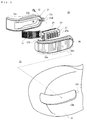
- FIG. 2 is an exploded perspective view showing the side mirror cover
- FIG. 3 is a cross sectional view of a vehicle side mirror with the cover mounted on a side mirror body, taken along the line A-A in FIG. 4;
- FIG. 4 is a front view of a vehicle on which the vehicle side mirror is mounted;
- FIG. 5 is a drawing showing the range in which the lamp is visible.
- FIG. 6 is a cross sectional view corresponding to FIG. 1 showing another side mirror cover according to the invention.
- a vehicle 10 is provided with direction indicator lamps 11 , 11 for indicating the turning direction of the vehicle 10 and the head lamps 12 , 12 as a illuminating device for night drive at the front end on both sides respectively, and a bumper 10 a mounted below the lead lamps is provided with front position lights 13 , 13 for allowing the oncoming cars and the third parties walking on the street to recognize the width of the vehicle 10 at night at both ends thereof respectively.
- the vehicle 10 in this embodiment is so called passenger car in the sedan category, and is adapted in such a manner that the oncoming cars and the third parties walking on the street can recognize the width of the vehicle 10 by the front position lamps 13 , 13 .
- Doors 10 b on both side of the vehicle 10 are provided with sideways projecting vehicle side mirrors 14 , 14 respectively thereon.
- These side mirrors 14 , 14 are fabricated to be symmetrical and ensure that the driver has a clear view to the rear of the vehicle 10 without turning his/her head owing to these side mirrors 14 , 14 .
- the vehicle side mirror 14 on the driver side will be described as an example.
- the vehicle side mirror 14 comprises the side mirror body 16 and the side mirror cover 21
- the side mirror body 16 comprises a mounting member 17 , a mirror plate 18 , and a tilting device 19 .
- the mirror plate 18 is mounted on the mounting member 17 with the light-reflecting surface faced toward the rear of the vehicle, so that light from the rear of the vehicle may be reflected toward the driver.
- the mirror plate 18 is mounted on the mounting member 17 via the tilting device 19
- the mounting member 17 is mounted at the front end of a side window on the door of the vehicle 10 .
- the mounting member 17 is curved out at the substantially center thereof toward the front of the vehicle so as to cover the mirror plate 18 , and the tilting device 19 is mounted inside the curved out mounting member 17 .
- the tilting device 19 includes a plurality of supporting rods 19 a that move in the for-and-aft direction of the vehicle by a motor (not shown) integrated therein, and the mirror plate 18 is mounted on the distal ends of the plurality of supporting rods 19 a .
- the tilting device 19 is capable of tilting the mirror plate 18 with respect to the perpendicular direction or the direction of the width of the vehicle by moving the respective supporting rods 19 a independently.
- the side mirror cover 21 comprises a mirror cover body 22 covering the front surface of the side mirror body 16 so as to curve out toward the front of the vehicle, and a cover lamp 23 mounted from the backside of the mirror cover body 22 .
- the mirror cover body 22 in this embodiment is formed by molding resin, and formed to curve out toward the front of the vehicle at the substantially center thereof corresponding to the configuration of the mounting member 17 so as to cover the mounting member 17 from the front surface.
- the mirror cover body 22 is provided with a laterally elongated through hole 22 b extending along the widthwise direction of the vehicle and having the outer end at the extremity of the mirror cove body 22 (FIG. 2).
- the mirror cover body 22 is adapted to be capable of being mounted on the front surface of the side mirror body 16 by applying a double-faced adhesive tape (not shown) on the inner surface thereof and then inserting the mirror cover body 22 into the mounting member 17 from the front.
- the cover lamp 23 is fitted from the backside of the mirror cover body 22 into the through hole 22 b from the backside of the mirror cover body 22 , and comprises a lamp housing 24 and a lamp cover 26 .
- the lamp housing 24 is mounted on the mirror cover body 22 along the peripheral edge of the through hole 22 b so as to close up the through hole 22 b, and the lamp cover 26 is formed by molding translucent resin.
- the lamp housing 24 is provided with a plurality of light emitting elements 27 , and the lamp cover 26 covers these plurality of light emitting elements 27 and is mounted on one or both of the lamp housing 24 and the mirror cover body 22 .
- the lamp housing 24 comprises a curved first corner section 24 a for closing up mainly the part of the through hole 22 b corresponding to the widthwise extremity of the vehicle and a first principal portion 24 b continuing from the first corner section 24 a for closing up the remainder of the through hole 22 b
- the lamp cover 26 comprises the second corner section 26 a facing toward the first corner section 24 a and the second principal portion 26 b continuing from the second corner section 26 a and facing toward the first principal portion 24 b .
- the plurality of light emitting elements 27 are provided on the first principal portion 24 b , and comprises one or more first LED or LEDs 27 a provided on the first principal portion 24 b for emitting light toward the front of the vehicle and one or more second LED or LEDs 27 b for emitting light toward the side of the vehicle.
- the second LED or LEDs 27 b are provided on the first principal portion 24 b on the far side from the vehicle.
- the second principal portion 26 b is formed with concavities and convexities on the inner surface thereof, so that light emitted from the first LED 27 a is refracted by and passes through concavities and convexities formed on the inner surface of the second principal portion 26 b , and is emitted from the second principal portion toward the front of the vehicle.
- the lamp cover 26 is formed with a projected portion 26 c on the inner surface thereof so as to face toward the second LED 27 b
- the second corner section 26 a is formed with concavities and convexities oriented in parallel with the vertical direction and aligned continuously in the direction of the width of the vehicle on the inner surface thereof.
- a part of light emitted from the second LED 27 b and passed from the projected portion 26 c through the inside of the lamp cover toward the outer end widthwise of the vehicle is reflected on the concavities and convexities formed on the inner surface of the second corner section 26 a and is emitted from the second corner section toward the front and the side of the vehicle, and the remainder of the light is emitted from the outer end of the second corner section 26 a toward the backside of the vehicle.
- the first LEDs 27 a as the plurality of light emitting elements 27 are mounted on the base as the support 28 , and are accommodated in the lamp housing 24 .
- the support 28 is provided with the first light reflector 29 on the surface facing toward the lamp cover 26
- the lamp housing 24 is provided at the first corner section 24 a with the second light reflector 31 curved along the configuration thereof.
- the first and second light reflectors 29 , 31 in this embodiment are resin molds and fabricated by applying metal plating on the surface thereof.
- Two or more first LEDs 27 a may be inserted into the first light reflector 29 , in which a plurality of holes 29 a that increase in diameter toward the lamp cover 26 are formed and light emitted from the first LED 27 a toward the surroundings reflects on the metal plate applied on the inner surface of the holes 29 a and is directed toward the lamp cover 26 .
- the cover lamp 23 is fabricated by adhering the peripheral edge of the lamp cover 26 on the peripheral edge of the lamp housing 24 including the plurality of light emitting elements 27 by the use of adhesive agent, and formed with a recessed groove 23 a defined by the outer end portion of the first corner section 24 a and the outer end portion of the second corner section 26 a in the adhered state, which is capable of being fitted on the peripheral edge of the through hole 22 b on the far side from the vehicle.
- the first principal portion 24 b is formed with a flange 24 c having a mounting hole 24 d at the inner end portion thereof.
- the mirror cover body 22 is formed with a boss 22 c at the peripheral edge of the through hole 22 b on the side closer to the vehicle, and the cover lamp 23 is mounted on the mirror cover body 22 by fitting the recessed groove 23 a on to the peripheral edge of the through hole 22 b on the far side from the vehicle, and in this state, passing a screw 32 through the mounting hole 24 d and screwing into the boss 22 c.
- the side mirror cover 21 including the mirror cover body 22 and the cover lamp 23 is capable mounted on the front surface of the side mirror body 16 by being applied with a double-faced adhesive tape (not shown) on the inner surface thereof and then inserted into the mounting member 17 of the side mirror body 16 from the front. Therefore, the cover lamp 23 cannot be removed from the mirror cover body 22 unless the mirror cover body 22 is removed from the mounting member 17 .
- the cover lamp 23 is electrically connected to the direction indicator lamps 11 of the vehicle 10 in the state of being mounted on the side mirror body 16 .
- lead wires (not shown) connected to the plurality of light emitting elements 27 at one end thereof are disposed in the interior of the vehicle 10 and are connected lead wires that supply a power to the direction indicator lamps 11 of the vehicle 10 on the other end. Accordingly, when a power is supplied and the direction indicator lamp 11 is flickered, the lead wires are also supplied with a power, and thus the plurality of light emitting elements 27 are flickered.
- Light emitted from the first LEDs 27 a in the plurality of light emitting elements 27 passes through the second principal portion 26 b directly or after being reflected on the first light reflector 29 and refracted by the concavities and convexities formed on the inner surface of the second principal portion 26 b of the lamp cover 26 , and is emitted from the second principal portion toward the front of the vehicle, whereby the oncoming cars approaching from the front can recognize the turning direction of the vehicle.
- the illumination shown in FIG. 5 can be recognized from the surroundings of the vehicle in relatively wide range.
- the turning direction of the vehicle can also be recognized by the third parties on the street behind the vehicle, or the driver in the vehicle approaching from behind, whereby the drivers of the vehicles and the third parties on the street can effectively avoid contact with the vehicle 10 , thereby ensuring a sufficient safety.
- the second LEDs 27 b may be provided on the side of the first principal portion 24 b on the side closer to the vehicle 10 , as shown in FIG. 6.
- the projected portion 26 c facing toward the second LEDs 27 b is also formed on the inner surface of the lamp cover 26 on the side closer to the vehicle 10 . Consequently, light emitted from the second LED 27 b passes from the projected portion 26 c through the second principal portion 26 b and the second corner section 26 a toward the widthwise end of the vehicle 10 .
- a part of the light reflects on the concavities and convexities on the inner surface of the second corner section 26 a and is emitted from the second corner section 26 a toward the front and the side of the vehicle 10 , while the remainder of the light is emitted from the outer end portion of the second corner section 26 a toward the backside of the vehicle 10 .
- the lamp cover 26 covers the plurality of light emitting elements 27 and is adhered on the lamp housing 24 in the embodiment described above, it is also possible to mount the lamp cover 26 on the mirror cover body 22 and adhere the lamp housing to the lamp cover 26 .
- the lamp housing comprises the curved first corner section for closing up mainly the part of the through hole corresponding to the widthwise end of the vehicle, and the first principal portion continuing from the first corner section for closing up the remainder of the through hole
- the lamp cover comprises the second corner section facing toward the first corner section and the second principal portion continuing from the second corner section and facing toward the first principal portion
- the plurality of light emitting elements comprises one or more first LEDs provided on the first principal portion for emitting light toward the front of the vehicle and one or more second LEDs for emitting light toward the side of the vehicle.
- the first light reflector is provided on the support having the plurality of light emitting elements mounted thereon on the surface facing toward the lamp cover, and the curved second light reflector on the first corner section of the lamp housing, light emitted from the light emitting elements reflects toward the front of the vehicle or toward the front and the side of the vehicle owing to the presence of these light reflectors, whereby light can be effectively recognized by the third parties or the drivers in other vehicles in the surroundings of the vehicle.
- the cover lamp is formed with a recessed groove at the outer end thereof, which is capable of being fitted on the peripheral edge of the through hole on the far side from the vehicle, and formed with the flange having the mounting hole at the inner end of the first principal portion, and the mirror cover body is formed with the boss at the peripheral edge of the through hole on the side closer to the vehicle, the cover lamp can be mounted on the mirror cover body by relatively simple process of fitting the recessed groove onto the peripheral edge of the through hole on the far side from the vehicle, and in this state, passing the screw through the mounting hole and screwing it into the boss. Consequently, the cover lamp is effectively prevented from being removed from the mirror cover body.
Landscapes
- Engineering & Computer Science (AREA)
- Mechanical Engineering (AREA)
- Multimedia (AREA)
- Lighting Device Outwards From Vehicle And Optical Signal (AREA)
Abstract
Description
- 1. Field of the Invention
- The present invention relates to a side mirror cover for covering a side mirror body provided projectingly from the side of the vehicle, and a cover lamp to be used for this cover.
- 2. Description of the Related Art
- Heretofore, a vehicle is provided with sideways projecting side mirrors on both sides of the vehicle body as well as a room mirror provided in the interior of the car for a driver to look behind for traffic. These mirrors ensure that the driver has a clear view to the rear of the vehicle without turning his/her head toward the rear. Although the room mirror and the side mirror are standardized according to the type of vehicle, the side mirror being partly responsible for the appearance of vehicle are figured to satisfy the sense of beauty. The side mirrors for passenger vehicles are mainly mounted on the doors, and figured to satisfy the sense of beauty considering the total appearance of vehicle. Further, there is a need for ornate side mirrors depending on the taste of consumers because of recent diversification of the taste of the consumers.
- At the front end of the vehicle, there are provided front position lights for allowing oncoming cars and the third parties walking on the street to recognize the width of the vehicle at night as well as direction indicator lamps for indicating the turning directions of the vehicle and headlamps as an illuminating device for nigh drive. The oncoming cars and the third parties walking on the street can recognize the width of the vehicle from the front position lights and the turning direction of the vehicle from flickering of the direction indicator lamp. The oncoming cars and the third parties walking on the street ensure the safety by driving or walking while avoiding contact with the vehicle.
- On the other hand, since the front position lights in the related art are provided at the front end of the vehicle, there is a problem in that the width of the vehicle body at the front end of the vehicle can be recognized, but the width of the entire vehicle including the side mirrors cannot be recognized. In other words, since the sideways projecting side mirrors are provided on the vehicle body, the width of the entire vehicle including the side mirrors is larger than the width indicated by the front position lights. Therefore, the oncoming cars or the third parties walking on the street are required to estimate the width of the entire vehicle by adding the estimated amount of projection of the side mirrors to the width indicated by the front position lights. However, since the amount of projection differs depending on the type of vehicle, it is relatively difficult to estimate. Especially, such estimation is difficult in the case of vehicles having side mirrors that project sideways significantly from the vehicle body such as heavy-duty trucks.
- In order to solve these problems, a side mirror cover including a mirror cover body adapted to be capable of being mounted on the front surface of the side mirror body of the vehicle and a cover lamp mounted on the mirror cover body so as to be visible from the front of the vehicle is proposed (Japanese Patent No. 3030021). Since such side mirror covers are adapted to be attached independently on the front surface of the side mirror body, and thus the covers can be formed into complex configurations, or colored or plated in themselves, high value-added side mirror covers are obtained at a lower cost than the case of forming or processing the entire side mirror into such configurations. Furthermore, when the cover lamps mounted on the mirror cover bodies are illuminated, the positions of the side mirrors are visible from the front, and thus the width of the entire vehicle including the side mirrors can be recognized.
- However, considering a case in which the cover lamp mounted on the mirror cover body is used as a direction indicator lamp, it is preferable that flickering of the cover lamp is recognized not only by the oncoming cars, but also the third parties walking by the side of the vehicle. In this case, it is conceivable to provide a separate side lamp at the laterally outer end portion of the mirror cover body (U.S. Pat. No. 5,499,169). However, there are such disadvantages that the appearance is deteriorated because the number of lamps to be mounted increases, and that the unit cost is increased due to increase in manufacturing cost and in number of components.
- Accordingly, it is an object of the present invention to provide a relatively less expensive side mirror cover in which flickering or illumination of a cover lamp is visible also from the side of the vehicle, and a lamp to be used therefor.
- It is another object of the invention to provide a side mirror cover in which flickering or illumination of a cover lamp is effectively visible from a wide range including the backside of the vehicle, and a lamp to be used therefor.
- It is still another object of the invention to provide a side mirror cover that can be mounted on the mirror cover body in a relatively simple process, and a lamp to be used therefor.
- As shown in FIGS. 1, 3, and 4, the first aspect of the invention is an improved side mirror cover comprising a
mirror cover body 22 for covering the front surface of a side mirror body 16 of avehicle 10, curved out toward the front of thevehicle 10, and formed with athorough hole 22 b having the outer end at the position corresponding to the widthwise extremity of thevehicle 10, and acover lamp 23 fitted from the backside of themirror cover body 22 into thethrough hole 22 b. - The characteristic construction of the side mirror cover is that the
cover lamp 23 includes alamp housing 24 mounted on themirror cover body 22 along the peripheral edge of the throughhole 22 b formed on themirror cover body 22 so as to close up the throughhole 22 b and provided with a plurality oflight emitting elements 27, and atranslucent lamp cover 26 mounted on either one or both of thelamp housing 24 and themirror cover body 22 so as to cover the plurality oflight emitting elements 27, in that thelamp housing 24 includes a curvedfirst corner section 24 a for closing up mainly the portion of the throughhole 22 b corresponding to the widthwise extremity of thevehicle 10 and a firstprincipal portion 24 b continuing from thefirst corner section 24 a for closing up the remainder of the throughhole 22 b, in that thelamp cover 26 includes asecond corner section 26 a opposing to thefirst corner section 24 a and a secondprincipal position 26 b continuing from thesecond corner section 26 a and opposing to the firstprincipal portion 24 b, and in that the plurality oflight emitting elements 27 include one or more first LED orLEDs 27 a provided on the firstprincipal portion 24 b for emitting light toward the front of thevehicle 10, and one or more second LED orLEDs 27 b for emitting light toward the side of thevehicle 10. - The second aspect of the invention is an improved
cover lamp 23 to be fitted from the backside of themirror cover body 22 into a throughhole 22 b of themirror cover body 22 for covering the front surface of a side mirror body 16 on thevehicle 10, curved out toward the front of thevehicle 10, and formed with thethorough hole 22 b having the outer end at the position corresponding to the widthwise extremity of thevehicle 10 from the backside of themirror cover body 22. - The characteristic construction of the
cover lamp 23 is that the cover lamp comprises alamp housing 24 mounted on themirror cover body 22 along the peripheral edge of the throughhole 22 b so as to close up the throughhole 22 b and provided with a plurality oflight emitting elements 27 and atranslucent lamp cover 26 adhered on thelamp housing 24 so as to cover the plurality oflight emitting elements 27, in that thelamp housing 24 includes a curvedfirst corner section 24 a for closing up mainly the portion of the throughhole 22 b corresponding to the widthwise extremity of thevehicle 10 and a firstprincipal portion 24 b continuing from thefirst corner section 24 a for closing up the remainder of the throughhole 22 b, in that thelamp cover 26 includes asecond corner section 26 a opposing to thefirst corner section 24 a and a secondprincipal position 26 b continuing from thesecond corner section 26 a and opposing to the firstprincipal portion 24 b, and in that the plurality oflight emitting elements 27 include one or more first LED orLEDs 27 a provided on the firstprincipal portion 24 b for emitting light toward the front of thevehicle 10 and one or more second LED orLEDs 27 b for emitting light toward the side of thevehicle 10. - With the side mirror cover according to the first aspect of the invention and the cover lamp according to the second aspect of the invention, light emitted from the one or more first LED or
LEDs 27 a for emitting light toward the front of thevehicle 10 is directed toward the front of the vehicle through the secondprincipal portion 26 b of thelamp cover 26, and light emitted from the one or more second LED orLEDs 27 b for emitting light toward the side of thevehicle 10 is directed toward the front and the side of thevehicle 10 through thesecond corner section 26 a of thelamp cover 26. Consequently, light is visible from the side of the vehicle. - In a preferred arrangement of the side mirror cover according to the invention, the
second LED 27 b is provided on the firstprincipal portion 24 b on the far side from thevehicle 10, a projectedportion 26 c is formed on the inner surface of thelamp cover 26 so as to face toward thesecond LED 27 b, and thesecond corner section 26 a is formed with concavities and convexities on the inner surface thereof as shown in FIG. 1, so that light from thefirst LED 27 a passes through the secondprincipal portion 26 b and is emitted toward the front of thevehicle 10, and light from thesecond LED 27 b passes through the projectedportion 26 c and thesecond corner section 26 a toward the outer end widthwise of thevehicle 10, reflects on the concavities and convexities on the inner surface of thesecond corner section 26 a, and is emitted from thesecond corner section 26 a toward the front and the side of thevehicle 10 and simultaneously from the outer end of thesecond corner section 26 a toward the backside of thevehicle 10. - In the preferred arrangement of the
cover lamp 23 according to the invention, thesecond LED 27 b is provided on the firstprincipal portion 24 b on the side of thesecond corner section 26 a, the projectedportion 26 c is formed on the inner surface of thelamp cover 26 so as to face toward thesecond LED 27 b, and thesecond corner section 26 a is formed with the concavities and convexities on the inner surface, so that light from thefirst LED 27 a passes through the secondprincipal portion 26 b and is emitted toward the front of thevehicle 10, and light from thesecond LED 27 b passes from the projectedportion 26 c through thesecond corner section 26 a toward the outer end widthwise of thevehicle 10, reflects on the concavities and convexities on the inner surface of thesecond corner section 26 a, and is emitted from thesecond corner section 26 a toward the front and the side of thevehicle 10 and simultaneously from the outer end of thesecond corner section 26 a toward the backside of thevehicle 10. - In the preferred arrangement of the side mirror cover according to the invention as shown in FIG. 6, the
second LED 27 b is provided on the firstprincipal portion 24 b on the side closer to thevehicle 10, the projectedportion 26 c is formed on the inner surface of thelamp cover 26 so as to face toward thesecond LED 27 b, and thesecond corner section 26 a is formed with the concavities and convexities on the inner surface, so that light from thefirst LED 27 a passes through the secondprincipal portion 26 b and is emitted toward the front of thevehicle 10, and light from thesecond LED 27 b passed from the projectedportion 26 c through the secondprincipal portion 26 b and thesecond corner section 26 a toward the outer end widthwise of thevehicle body 10, reflects on the concavities and convexities on the inner surface of thesecond corner section 26 a, and is emitted from thesecond corner section 26 a to the front and the side of thevehicle 10 and simultaneously from the outer end of thesecond corner section 26 a toward the backside of thevehicle 10. - In the preferred arrangement of the cover lamp according to the invention, the
second LED 27 b is provided on the firstprincipal portion 24 b on the side opposite from thesecond corner section 26 a, the projectedportion 26 c is formed on the inner surface of thelamp cover 26 so as to face toward thesecond LED 27 b, and thesecond corner section 26 a is formed with the concavities and convexities on the inner surface, so that light from thefirst LED 27 a passed through the secondprincipal portion 26 b and is emitted toward the front of thevehicle 10, and light from thesecond LED 27 b passes from the projectedportion 26 c through thesecond principal portion 26 b and thesecond corner section 26 a toward the outer end widthwise of thevehicle 10, reflects on the concavities and convexities on the inner surface of thesecond corner section 26 a, and is emitted from thesecond corner section 26 a toward the front and the side of thevehicle 10 and simultaneously from the outer end of thesecond corner section 26 a toward the backside of thevehicle 10. - In these arrangements, since light emitted from the
second LED 27 b is directed not only toward the front and the side of the vehicle but also through the outer end of thesecond corner section 26 a toward the backside of the vehicle, light is visible also from the backside of the vehicle. - In the preferred arrangement of the side mirror cover according to the invention, the plurality of
light emitting elements 27 are mounted on asupport 28 and accommodated in thelamp housing 24, and afirst light reflector 29 is provided on thesupport 28 on the surface facing toward thelamp cover 26. - In the preferred arrangement of the cover lamp according to the invention, the plurality of
light emitting elements 27 are mounted on thesupport 28 and accommodated in thelamp housing 24, and thefirst light reflector 29 is provided on the surface of thesupport 28 facing toward thelamp cover 26. - In the preferred arrangement of the side mirror cover according to the invention, a curved
second light reflector 31 is provided on thefirst corner section 24 a of thelamp housing 24. - In the preferred arrangement of the cover lamp according to the invention, the curved
second light reflector 31 is mounted on thefirst corner section 24 a of thelamp housing 24. - In these arrangements, light emitted from the
light emitting element 27 reflects toward the front of the vehicle or toward the front and the side of the vehicle owing to the presence of thelight reflectors - In the preferred arrangement of the side mirror cover according to the invention, the
cover lamp 23 is fabricated by adhering the peripheral edge of thelamp cover 26 to the peripheral edge of thelamp housing 24, is formed with arecessed groove 23 a defined by the outer end portion of thefirst corner section 24 a and the outer end portion of thesecond corner section 26 a in the adhered state, which is capable of being fitted on the peripheral edge of the throughhole 22 b on the far side from thevehicle 10, and formed with aflange 24 c having amounting hole 24 d at the inner end of the firstprincipal portion 24 b, themirror cover body 22 is formed with aboss 22 c at the peripheral edge of the throughhole 22 b on the side closer to thevehicle 10, and thecover lamp 23 is mounted on themirror cover body 22 by fitting therecessed groove 23 a onto the peripheral edge of the throughhole 22 b on the far side from thevehicle 10, passing ascrew 32 through themounting hole 24 d and screwing it into theboss 22 c. - In the preferred arrangement of the cover lamp according to the invention, the
recessed groove 23 a which is capable of being fitted on the peripheral edge of the throughhole 22 b on the far side from thevehicle 10 is defined by the outer end portion of thefirst corner section 24 a and the outer end portion of thesecond corner section 26 a in a state in which the peripheral edge of thelamp housing 24 and the peripheral edge of thelamp cover 26 are adhered, and theflange 24 c having themounting hole 24 d is formed at the inner end portion of the firstprincipal portion 24 b. - In these arrangements, the
cover lamp 23 can be mounted on themirror cover body 22 by such a relatively simple process of fitting therecessed groove 23 a on the peripheral edge of the throughhole 22 b on the far side from thevehicle 10, and in this state, screwing thescrew 32 passed through themounting hole 24 d into theboss 22 c. - FIG. 1 is a cross sectional view of a side mirror cover of the invention taken along the line B-B in FIG. 3;
- FIG. 2 is an exploded perspective view showing the side mirror cover;
- FIG. 3 is a cross sectional view of a vehicle side mirror with the cover mounted on a side mirror body, taken along the line A-A in FIG. 4;
- FIG. 4 is a front view of a vehicle on which the vehicle side mirror is mounted;
- FIG. 5 is a drawing showing the range in which the lamp is visible; and
- FIG. 6 is a cross sectional view corresponding to FIG. 1 showing another side mirror cover according to the invention.
- Referring now to the drawings, an embodiment of the invention will be described in detail.
- As shown in FIG. 4, a
vehicle 10 is provided withdirection indicator lamps vehicle 10 and thehead lamps bumper 10 a mounted below the lead lamps is provided withfront position lights vehicle 10 at night at both ends thereof respectively. Thevehicle 10 in this embodiment is so called passenger car in the sedan category, and is adapted in such a manner that the oncoming cars and the third parties walking on the street can recognize the width of thevehicle 10 by thefront position lamps Doors 10 b on both side of thevehicle 10 are provided with sideways projectingvehicle side mirrors side mirrors vehicle 10 without turning his/her head owing to theseside mirrors - The
side mirror 14 on the driver side will be described as an example. As shown in FIG. 3, thevehicle side mirror 14 comprises the side mirror body 16 and theside mirror cover 21, and the side mirror body 16 comprises amounting member 17, a mirror plate 18, and atilting device 19. The mirror plate 18 is mounted on the mountingmember 17 with the light-reflecting surface faced toward the rear of the vehicle, so that light from the rear of the vehicle may be reflected toward the driver. The mirror plate 18 is mounted on the mountingmember 17 via thetilting device 19, and the mountingmember 17 is mounted at the front end of a side window on the door of thevehicle 10. The mountingmember 17 is curved out at the substantially center thereof toward the front of the vehicle so as to cover the mirror plate 18, and thetilting device 19 is mounted inside the curved out mountingmember 17. The tiltingdevice 19 includes a plurality of supportingrods 19 a that move in the for-and-aft direction of the vehicle by a motor (not shown) integrated therein, and the mirror plate 18 is mounted on the distal ends of the plurality of supportingrods 19 a. The tiltingdevice 19 is capable of tilting the mirror plate 18 with respect to the perpendicular direction or the direction of the width of the vehicle by moving the respective supportingrods 19 a independently. - The
side mirror cover 21 comprises amirror cover body 22 covering the front surface of the side mirror body 16 so as to curve out toward the front of the vehicle, and acover lamp 23 mounted from the backside of themirror cover body 22. Themirror cover body 22 in this embodiment is formed by molding resin, and formed to curve out toward the front of the vehicle at the substantially center thereof corresponding to the configuration of the mountingmember 17 so as to cover the mountingmember 17 from the front surface. Themirror cover body 22 is provided with a laterally elongated throughhole 22 b extending along the widthwise direction of the vehicle and having the outer end at the extremity of the mirror cove body 22 (FIG. 2). Themirror cover body 22 is adapted to be capable of being mounted on the front surface of the side mirror body 16 by applying a double-faced adhesive tape (not shown) on the inner surface thereof and then inserting themirror cover body 22 into the mountingmember 17 from the front. - As shown in FIG. 1 to FIG. 3, the
cover lamp 23 is fitted from the backside of themirror cover body 22 into the throughhole 22 b from the backside of themirror cover body 22, and comprises alamp housing 24 and alamp cover 26. Thelamp housing 24 is mounted on themirror cover body 22 along the peripheral edge of the throughhole 22 b so as to close up the throughhole 22 b, and thelamp cover 26 is formed by molding translucent resin. Thelamp housing 24 is provided with a plurality oflight emitting elements 27, and thelamp cover 26 covers these plurality oflight emitting elements 27 and is mounted on one or both of thelamp housing 24 and themirror cover body 22. - As shown in FIG. 1, the
lamp housing 24 comprises a curvedfirst corner section 24 a for closing up mainly the part of the throughhole 22 b corresponding to the widthwise extremity of the vehicle and a firstprincipal portion 24 b continuing from thefirst corner section 24 a for closing up the remainder of the throughhole 22 b, and thelamp cover 26 comprises thesecond corner section 26 a facing toward thefirst corner section 24 a and the secondprincipal portion 26 b continuing from thesecond corner section 26 a and facing toward the firstprincipal portion 24 b. The plurality oflight emitting elements 27 are provided on the firstprincipal portion 24 b, and comprises one or more first LED orLEDs 27 a provided on the firstprincipal portion 24 b for emitting light toward the front of the vehicle and one or more second LED orLEDs 27 b for emitting light toward the side of the vehicle. In this embodiment, the second LED orLEDs 27 b are provided on the firstprincipal portion 24 b on the far side from the vehicle. - The second
principal portion 26 b is formed with concavities and convexities on the inner surface thereof, so that light emitted from thefirst LED 27 a is refracted by and passes through concavities and convexities formed on the inner surface of the secondprincipal portion 26 b, and is emitted from the second principal portion toward the front of the vehicle. On the other hand, thelamp cover 26 is formed with a projectedportion 26 c on the inner surface thereof so as to face toward thesecond LED 27 b, and thesecond corner section 26 a is formed with concavities and convexities oriented in parallel with the vertical direction and aligned continuously in the direction of the width of the vehicle on the inner surface thereof. A part of light emitted from thesecond LED 27 b and passed from the projectedportion 26 c through the inside of the lamp cover toward the outer end widthwise of the vehicle is reflected on the concavities and convexities formed on the inner surface of thesecond corner section 26 a and is emitted from the second corner section toward the front and the side of the vehicle, and the remainder of the light is emitted from the outer end of thesecond corner section 26 a toward the backside of the vehicle. - The
first LEDs 27 a as the plurality oflight emitting elements 27 are mounted on the base as thesupport 28, and are accommodated in thelamp housing 24. Thesupport 28 is provided with thefirst light reflector 29 on the surface facing toward thelamp cover 26, and thelamp housing 24 is provided at thefirst corner section 24 a with the secondlight reflector 31 curved along the configuration thereof. As shown in FIG. 2 in detail, the first and secondlight reflectors first LEDs 27 a may be inserted into thefirst light reflector 29, in which a plurality ofholes 29 a that increase in diameter toward thelamp cover 26 are formed and light emitted from thefirst LED 27 a toward the surroundings reflects on the metal plate applied on the inner surface of theholes 29 a and is directed toward thelamp cover 26. - The
cover lamp 23 is fabricated by adhering the peripheral edge of thelamp cover 26 on the peripheral edge of thelamp housing 24 including the plurality oflight emitting elements 27 by the use of adhesive agent, and formed with a recessedgroove 23 a defined by the outer end portion of thefirst corner section 24 a and the outer end portion of thesecond corner section 26 a in the adhered state, which is capable of being fitted on the peripheral edge of the throughhole 22 b on the far side from the vehicle. On the other hand, the firstprincipal portion 24 b is formed with aflange 24 c having a mountinghole 24 d at the inner end portion thereof. Further, themirror cover body 22 is formed with aboss 22 c at the peripheral edge of the throughhole 22 b on the side closer to the vehicle, and thecover lamp 23 is mounted on themirror cover body 22 by fitting the recessedgroove 23 a on to the peripheral edge of the throughhole 22 b on the far side from the vehicle, and in this state, passing ascrew 32 through the mountinghole 24 d and screwing into theboss 22 c. - The side mirror cover 21 including the
mirror cover body 22 and thecover lamp 23 is capable mounted on the front surface of the side mirror body 16 by being applied with a double-faced adhesive tape (not shown) on the inner surface thereof and then inserted into the mountingmember 17 of the side mirror body 16 from the front. Therefore, thecover lamp 23 cannot be removed from themirror cover body 22 unless themirror cover body 22 is removed from the mountingmember 17. Thecover lamp 23 is electrically connected to thedirection indicator lamps 11 of thevehicle 10 in the state of being mounted on the side mirror body 16. In other words, lead wires (not shown) connected to the plurality oflight emitting elements 27 at one end thereof are disposed in the interior of thevehicle 10 and are connected lead wires that supply a power to thedirection indicator lamps 11 of thevehicle 10 on the other end. Accordingly, when a power is supplied and thedirection indicator lamp 11 is flickered, the lead wires are also supplied with a power, and thus the plurality oflight emitting elements 27 are flickered. - With the
vehicle side mirror 14 in this arrangement, when the driver of thevehicle 10 in FIG. 4 flickers thedirection indicator lamp 11 before turning the vehicle, the plurality oflight emitting elements 27 in thecover lamp 23 on theside mirror 14 located on the outer extremity of thevehicle 10 and connected to thedirection indicator lamp 11 flicker. Light emitted from thefirst LEDs 27 a in the plurality oflight emitting elements 27 passes through the secondprincipal portion 26 b directly or after being reflected on thefirst light reflector 29 and refracted by the concavities and convexities formed on the inner surface of the secondprincipal portion 26 b of thelamp cover 26, and is emitted from the second principal portion toward the front of the vehicle, whereby the oncoming cars approaching from the front can recognize the turning direction of the vehicle. - On the other hand, light emitted from the
second LEDs 27 b in the plurality oflight emitting elements 27 passes from the projectedportion 26 c through the inside of thelamp cover 26 toward the outer end widthwise of the vehicle, and a part of light is reflected on the concavities and convexities formed on the inner surface of thesecond corner section 26 a and emitted from the second corner section toward the front and the side of the vehicle. As a consequent, the third parties walking on the street on the side of the vehicle or the driver in the vehicle approaching from the side toward the vehicle at an intersection can recognize the turning direction of the vehicle. Light passing through the inside of the lamp cover toward the outer end widthwise of the vehicle is finally emitted from the outer end portion of thesecond corner section 26 a toward the backside of the vehicle, and thus the illumination shown in FIG. 5 can be recognized from the surroundings of the vehicle in relatively wide range. As a consequent, the turning direction of the vehicle can also be recognized by the third parties on the street behind the vehicle, or the driver in the vehicle approaching from behind, whereby the drivers of the vehicles and the third parties on the street can effectively avoid contact with thevehicle 10, thereby ensuring a sufficient safety. - Though the case in which the
second LEDs 27 b are provided in the firstprincipal portion 24 b on the far side from the vehicle has been described in the preceding embodiment, thesecond LEDs 27 b may be provided on the side of the firstprincipal portion 24 b on the side closer to thevehicle 10, as shown in FIG. 6. In such a case, the projectedportion 26 c facing toward thesecond LEDs 27 b is also formed on the inner surface of thelamp cover 26 on the side closer to thevehicle 10. Consequently, light emitted from thesecond LED 27 b passes from the projectedportion 26 c through the secondprincipal portion 26 b and thesecond corner section 26 a toward the widthwise end of thevehicle 10. Then a part of the light reflects on the concavities and convexities on the inner surface of thesecond corner section 26 a and is emitted from thesecond corner section 26 a toward the front and the side of thevehicle 10, while the remainder of the light is emitted from the outer end portion of thesecond corner section 26 a toward the backside of thevehicle 10. - Though the
lamp cover 26 covers the plurality oflight emitting elements 27 and is adhered on thelamp housing 24 in the embodiment described above, it is also possible to mount thelamp cover 26 on themirror cover body 22 and adhere the lamp housing to thelamp cover 26. - As is described thus far, according to the invention, the lamp housing comprises the curved first corner section for closing up mainly the part of the through hole corresponding to the widthwise end of the vehicle, and the first principal portion continuing from the first corner section for closing up the remainder of the through hole, the lamp cover comprises the second corner section facing toward the first corner section and the second principal portion continuing from the second corner section and facing toward the first principal portion, and the plurality of light emitting elements comprises one or more first LEDs provided on the first principal portion for emitting light toward the front of the vehicle and one or more second LEDs for emitting light toward the side of the vehicle. Therefore, light emitted from the first LED passes through the second principal portion in the lamp cover and is emitted toward the front of the vehicle, and light emitted from the second LEDs passes through the second corner section and is emitted toward the front and the side of the vehicle. Consequently, these lights can be recognized from the surroundings of the vehicle in relatively wide range.
- In this case, since the projected portion facing toward the second LEDs is formed on the inner surface of the lamp cover, and the inner surface of the second corner section is formed with the concavities and convexities, light emitted from the second LEDs passes from the curved-out portion through the interior of the lamp cover toward the outer end widthwise of the vehicle, and a part of the light reflects on the concavities and convexities formed on the inner surface of the second corner section and is emitted from the second corner section toward the front and the side of the vehicle. Consequently, the third parties or the drivers in other vehicles on the side of the vehicle can recognize the turning direction of the vehicle. Since light passing through the inside of the lamp cover toward the widthwise outer end is finally directed from the outer end of the second corner section also toward the backside of the vehicle, the third parties or the drivers on the backside of the vehicle can recognize the light.
- Since the first light reflector is provided on the support having the plurality of light emitting elements mounted thereon on the surface facing toward the lamp cover, and the curved second light reflector on the first corner section of the lamp housing, light emitted from the light emitting elements reflects toward the front of the vehicle or toward the front and the side of the vehicle owing to the presence of these light reflectors, whereby light can be effectively recognized by the third parties or the drivers in other vehicles in the surroundings of the vehicle.
- In addition, since the cover lamp is formed with a recessed groove at the outer end thereof, which is capable of being fitted on the peripheral edge of the through hole on the far side from the vehicle, and formed with the flange having the mounting hole at the inner end of the first principal portion, and the mirror cover body is formed with the boss at the peripheral edge of the through hole on the side closer to the vehicle, the cover lamp can be mounted on the mirror cover body by relatively simple process of fitting the recessed groove onto the peripheral edge of the through hole on the far side from the vehicle, and in this state, passing the screw through the mounting hole and screwing it into the boss. Consequently, the cover lamp is effectively prevented from being removed from the mirror cover body.
Claims (18)
Applications Claiming Priority (2)
| Application Number | Priority Date | Filing Date | Title |
|---|---|---|---|
| JP2002-109370 | 2002-04-11 | ||
| JP2002109370 | 2002-04-11 |
Publications (2)
| Publication Number | Publication Date |
|---|---|
| US20030193815A1 true US20030193815A1 (en) | 2003-10-16 |
| US6769798B2 US6769798B2 (en) | 2004-08-03 |
Family
ID=28786576
Family Applications (1)
| Application Number | Title | Priority Date | Filing Date |
|---|---|---|---|
| US10/187,661 Expired - Fee Related US6769798B2 (en) | 2002-04-11 | 2002-07-01 | Side mirror cover and cover lamp to be used therefor |
Country Status (1)
| Country | Link |
|---|---|
| US (1) | US6769798B2 (en) |
Cited By (48)
| Publication number | Priority date | Publication date | Assignee | Title |
|---|---|---|---|---|
| US20030174507A1 (en) * | 2002-03-13 | 2003-09-18 | Patent-Treuhand-Gesellschaft Fur Elektrisch Gluhlampen Mbh | Luminaire for installing in the cover cap of an exterior rearview mirror for motor vehicles |
| US20050117236A1 (en) * | 2003-10-07 | 2005-06-02 | Toyoda Gosei Co., Ltd. | Vehicle side mirror apparatus |
| EP1547864A1 (en) * | 2003-12-24 | 2005-06-29 | Ichikoh Industries, Ltd. | Vehicle mirror assembly that includes light unit |
| US20050146886A1 (en) * | 2003-12-24 | 2005-07-07 | Ichikoh Industries, Ltd. | Vehicle outside-mirror unit including lamp unit |
| US20050231970A1 (en) * | 2004-04-05 | 2005-10-20 | Honda Motor Co., Ltd. | External mirror having indicator light |
| WO2005118338A1 (en) * | 2004-06-04 | 2005-12-15 | Soon-Hyenog Park | The flank indicator lamp and a rear guard lamp |
| EP1657111A3 (en) * | 2004-11-15 | 2006-09-13 | FER Fahrzeugelektrik GmbH | Side blinker lamp |
| DE102005038154A1 (en) * | 2005-08-12 | 2007-02-15 | Bayerische Motoren Werke Ag | Luminaire for motor vehicles |
| US20070139955A1 (en) * | 2005-12-20 | 2007-06-21 | Valeo Vision | Lighting or signalling device with a light guide, for a motor vehicle |
| US20070195540A1 (en) * | 2006-01-30 | 2007-08-23 | Toyoda Gosei Co., Ltd. | Vehicle lighting system |
| US20080074891A1 (en) * | 2006-09-27 | 2008-03-27 | Chih-Cheng Chuang | Light |
| CN100402344C (en) * | 2004-01-14 | 2008-07-16 | 本田技研工业株式会社 | Lamp Body Control Device for Vehicles |
| US20080174893A1 (en) * | 2006-11-20 | 2008-07-24 | Schefenacker Patents S.A.R.L. | Exterior rearview mirror for vehicles, preferably for motor vehicles |
| FR2913934A1 (en) * | 2007-03-21 | 2008-09-26 | Peugeot Citroen Automobiles Sa | Bumper face bar forming device for motor vehicle, has case fixed on rear face of device at level of visibility window of section to maintain reflecting surface of retroreflector disposed with respect to visibility window |
| US20080247186A1 (en) * | 2007-03-30 | 2008-10-09 | Jun Watanabe | Vehicle lamp |
| US20090027911A1 (en) * | 2007-07-17 | 2009-01-29 | Toyoda Gosei Co., Ltd. | Vehicular lamp |
| US20090154186A1 (en) * | 2007-12-14 | 2009-06-18 | Koito Manufacturing Co., Ltd. | Vehicle lamp assembly |
| DE102008016174A1 (en) * | 2008-03-27 | 2009-10-01 | Hella Kgaa Hueck & Co. | Signal light for motor vehicles |
| US20100066249A1 (en) * | 2008-09-12 | 2010-03-18 | Daisuke Nagafuchi | Vehicle light |
| US20100103688A1 (en) * | 2008-10-24 | 2010-04-29 | Scott Arthur Riesebosch | Vehicle light |
| US20100290242A1 (en) * | 2005-09-01 | 2010-11-18 | Jens Fischer | Vehicle headlight |
| EP2159103A3 (en) * | 2008-08-28 | 2011-01-26 | Koito Manufacturing Co., Ltd | Vehicular Lamp |
| EP2258977A3 (en) * | 2009-06-05 | 2011-11-09 | Koito Manufacturing Co., Ltd. | Vehicular lamp |
| US20120069592A1 (en) * | 2010-09-17 | 2012-03-22 | Koito Manufacturing Co., Ltd. | Vehicular lamp |
| CN102788302A (en) * | 2011-05-18 | 2012-11-21 | 斯坦雷电气株式会社 | Vehicle lighting unit |
| WO2013013747A1 (en) * | 2011-07-26 | 2013-01-31 | Daimler Ag | Arrangement of an exterior rear view mirror on a body of a motor vehicle |
| US20130100693A1 (en) * | 2011-01-04 | 2013-04-25 | Kathleen Anne Johnson | Led tail light with side markers |
| US20130128620A1 (en) * | 2011-11-21 | 2013-05-23 | Koito Manufacturing Co., Ltd. | Vehicular lamp |
| US20130128601A1 (en) * | 2011-11-18 | 2013-05-23 | Sl Corporation | Integrated lamp device of vehicle side mirror |
| US20140092614A1 (en) * | 2012-10-01 | 2014-04-03 | Ford Global Technologies, Llc | Strobe mount for vehicle mirror |
| WO2014135762A1 (en) * | 2013-03-05 | 2014-09-12 | Peugeot Citroen Automobiles Sa | Device for indicating a change in direction of a vehicle, with light guide and opaline screen |
| CN104566098A (en) * | 2013-10-23 | 2015-04-29 | 光阳工业股份有限公司 | Lighting device |
| WO2016067185A1 (en) * | 2014-10-27 | 2016-05-06 | Smr Patents S.A.R.L. | A lamp assembly for a vehicle |
| EP2340967B2 (en) † | 2009-12-29 | 2016-09-14 | SMR Patents S.à.r.l. | Turn-indicator light module for a vehicle mirror assembly and vehicle mirror assembly comprising a turn-indicator light module |
| FR3056705A1 (en) * | 2016-09-28 | 2018-03-30 | Valeo Vision | LIGHT EMITTING MODULE WITH IMPROVED CONTROL, IN PARTICULAR FOR A MOTOR VEHICLE |
| GB2554403A (en) * | 2016-09-05 | 2018-04-04 | Jaguar Land Rover Ltd | A lamp assembly for an automobile, a headlamp comprising such a lamp assembly, and an automobile comprising such a lamp assembly |
| EP2447601A3 (en) * | 2010-10-28 | 2018-04-18 | Koito Manufacturing Co., Ltd. | Vehicle lamp |
| DE102016124748A1 (en) * | 2016-12-19 | 2018-06-21 | Dr. Ing. H.C. F. Porsche Aktiengesellschaft | Luminaire for a motor vehicle body |
| EP3418626A4 (en) * | 2016-02-15 | 2018-12-26 | LG Innotek Co., Ltd. | Lamp and vehicle having same |
| EP3539825A1 (en) * | 2018-03-12 | 2019-09-18 | Excellence Optoelectronics Inc. | Vehicle dual-functional lighting module and vehicle dual-functional lighting set |
| US20190309920A1 (en) * | 2016-12-23 | 2019-10-10 | Lumileds Llc | Light emitting module with light guide plate for automotive headlight |
| EP3623221A1 (en) * | 2018-09-13 | 2020-03-18 | Seat, S.A. | Headlamp for motor vehicle |
| US10845022B2 (en) * | 2016-09-28 | 2020-11-24 | Valeo Vision | Light-emitting module for a motor vehicle |
| US10895361B1 (en) * | 2019-08-22 | 2021-01-19 | Valeo North America, Inc. | Optical device for an automobile vehicle |
| US11002420B2 (en) | 2018-12-21 | 2021-05-11 | Magna Exteriors Inc. | Vehicle headlamp having light guide |
| US20210356093A1 (en) * | 2019-10-02 | 2021-11-18 | Valeo North America, Inc. | Automotive lighting |
| US20240230052A1 (en) * | 2023-01-06 | 2024-07-11 | Autosystems, A Division Of Magna Exteriors Inc. | Vehicle signal lighting assembly |
| DE102007038470B4 (en) | 2007-08-14 | 2025-07-31 | HELLA GmbH & Co. KGaA | Lighting equipment for vehicles |
Families Citing this family (37)
| Publication number | Priority date | Publication date | Assignee | Title |
|---|---|---|---|---|
| DE19959609A1 (en) * | 1999-12-10 | 2001-06-28 | Volkswagen Ag | Exterior rear-view mirror with integrated direction indicator |
| JP4086227B2 (en) * | 2002-12-09 | 2008-05-14 | 本田技研工業株式会社 | Rearview mirror device |
| DE20219483U1 (en) * | 2002-12-16 | 2003-05-08 | FER Fahrzeugelektrik GmbH, 99817 Eisenach | vehicle light |
| JP4262502B2 (en) * | 2003-03-25 | 2009-05-13 | 株式会社ミツバ | Door mirror with side blinker |
| DE102004015544B4 (en) * | 2003-03-31 | 2009-05-07 | Toyoda Gosei Co., Ltd. | LED light and side mirror device |
| US7513664B2 (en) * | 2004-05-10 | 2009-04-07 | Ichikoh Industries, Ltd. | Outside mirror apparatus including lighting device for vehicle |
| JP4321346B2 (en) * | 2004-05-10 | 2009-08-26 | 市光工業株式会社 | Outside mirror device for vehicle |
| DE102004046386A1 (en) * | 2004-09-24 | 2006-04-06 | Schefenacker Vision Systems Germany Gmbh & Co. Kg | Light guide for lights, in particular for lights of motor vehicles |
| JP4413764B2 (en) * | 2004-12-10 | 2010-02-10 | 株式会社小糸製作所 | Vehicle lighting |
| JP4569444B2 (en) * | 2005-11-09 | 2010-10-27 | 市光工業株式会社 | Outside mirror device for vehicle |
| DE102006025070A1 (en) * | 2006-05-23 | 2007-11-29 | Schefenacker Vision Systems Germany Gmbh | Exterior mirrors of a vehicle |
| JP2008097848A (en) * | 2006-10-06 | 2008-04-24 | Ichikoh Ind Ltd | Vehicle lighting |
| JP4631838B2 (en) | 2006-10-20 | 2011-02-16 | 市光工業株式会社 | Vehicle lighting |
| JP4631840B2 (en) * | 2006-11-02 | 2011-02-16 | 市光工業株式会社 | Vehicle lighting |
| JP5032163B2 (en) * | 2007-03-12 | 2012-09-26 | 株式会社ミツバ | Vehicle lamp |
| JP4930787B2 (en) * | 2007-07-27 | 2012-05-16 | スタンレー電気株式会社 | VEHICLE LIGHT AND LIGHT GUIDE LENS USED FOR VEHICLE LIGHT |
| JP5075572B2 (en) * | 2007-10-18 | 2012-11-21 | 株式会社ミツバ | door mirror |
| CN101959716B (en) * | 2008-03-03 | 2014-08-13 | 株式会社藤仓 | mirror device |
| JP2009218076A (en) * | 2008-03-10 | 2009-09-24 | Koito Mfg Co Ltd | Vehicular lighting fixture |
| US20100014308A1 (en) * | 2008-07-15 | 2010-01-21 | Triplex Manufacturing Company | Lighting apparatus and method of manufacture |
| FR2953276B1 (en) * | 2009-11-27 | 2011-11-18 | Peugeot Citroen Automobiles Sa | LIGHTING DEVICE WITH INTERCALE LIGHT GUIDE (S) BETWEEN A REFLECTOR AND A SCREEN |
| JP2011216279A (en) * | 2010-03-31 | 2011-10-27 | Koito Mfg Co Ltd | Lamp fitting for vehicle |
| US10576896B2 (en) * | 2010-10-01 | 2020-03-03 | Magna Mirrors Of America, Inc. | Vehicle exterior mirror system with light module |
| JP2012104275A (en) * | 2010-11-08 | 2012-05-31 | Koito Mfg Co Ltd | Door mirror lamp |
| DE102011105983A1 (en) * | 2011-06-29 | 2013-01-03 | SMR Patents S.à.r.l. | Close range cornering light in the exterior mirror |
| US10787177B2 (en) | 2011-06-29 | 2020-09-29 | SMR Patents S.à.r.l. | Exterior rearview device with illumination functions and autonomous vehicles using same |
| US10137823B2 (en) | 2011-06-29 | 2018-11-27 | SMR Patents S.à.r.l. | Exterior rearview device with illumination functions |
| ITTV20130033A1 (en) * | 2013-03-01 | 2014-09-02 | Automotive Lighting Italia Spa | AUTOMOTIVE HEADLIGHT |
| EP2803532B1 (en) | 2013-05-17 | 2017-11-01 | Fico Mirrors S.A. | Mirror device for motor vehicles |
| FR3026460B1 (en) * | 2014-09-30 | 2019-04-05 | Valeo Vision | OPTICAL SYSTEM FOR MOTOR VEHICLE |
| TWI607181B (en) * | 2015-07-06 | 2017-12-01 | 隆達電子股份有限公司 | Light-guiding pillar and vehicle lamp using the same |
| US10240742B2 (en) * | 2016-07-29 | 2019-03-26 | Valeo North America, Inc. | Vehicle lighting and signaling device having a lens with at least one coupler |
| EP3434473A1 (en) * | 2017-07-27 | 2019-01-30 | Zanini Auto Grup, S.A. | Emblem for vehicles |
| US10151436B1 (en) * | 2017-10-12 | 2018-12-11 | GM Global Technology Operations LLC | Vehicle lighting assembly with light transfer optical system |
| JP7419883B2 (en) * | 2020-03-04 | 2024-01-23 | オムロン株式会社 | Illumination devices and gaming machines |
| US11472334B1 (en) | 2021-04-14 | 2022-10-18 | Nikolay Pukharev | Automobile sideview mirror bracket for mounting auxiliary lights |
| US12228263B1 (en) * | 2024-02-22 | 2025-02-18 | Motherson Innovations Company Limited | Light module for an exterior mirror |
Citations (2)
| Publication number | Priority date | Publication date | Assignee | Title |
|---|---|---|---|---|
| US6264353B1 (en) * | 1998-11-23 | 2001-07-24 | Lear Automotive Dearborn, Inc. | Exterior mirror with supplement turn signal |
| US6299334B1 (en) * | 1999-01-21 | 2001-10-09 | Fer Fahrzeugelektrik Gmbh | Vehicle lamp |
-
2002
- 2002-07-01 US US10/187,661 patent/US6769798B2/en not_active Expired - Fee Related
Patent Citations (2)
| Publication number | Priority date | Publication date | Assignee | Title |
|---|---|---|---|---|
| US6264353B1 (en) * | 1998-11-23 | 2001-07-24 | Lear Automotive Dearborn, Inc. | Exterior mirror with supplement turn signal |
| US6299334B1 (en) * | 1999-01-21 | 2001-10-09 | Fer Fahrzeugelektrik Gmbh | Vehicle lamp |
Cited By (83)
| Publication number | Priority date | Publication date | Assignee | Title |
|---|---|---|---|---|
| US6893146B2 (en) * | 2002-03-13 | 2005-05-17 | Patent-Treuhand-Gesellschaft für Electrische Glühlampen mbH | Luminaire for installing in the cover cap of an exterior rearview mirror for motor vehicles |
| US20030174507A1 (en) * | 2002-03-13 | 2003-09-18 | Patent-Treuhand-Gesellschaft Fur Elektrisch Gluhlampen Mbh | Luminaire for installing in the cover cap of an exterior rearview mirror for motor vehicles |
| US7229197B2 (en) * | 2003-10-07 | 2007-06-12 | Toyoda Gosei Co., Ltd. | Vehicle side mirror apparatus |
| US20050117236A1 (en) * | 2003-10-07 | 2005-06-02 | Toyoda Gosei Co., Ltd. | Vehicle side mirror apparatus |
| US20050141229A1 (en) * | 2003-12-24 | 2005-06-30 | Ichikoh Industries, Ltd. | Vehicle mirror assembly that includes light unit |
| US20050146886A1 (en) * | 2003-12-24 | 2005-07-07 | Ichikoh Industries, Ltd. | Vehicle outside-mirror unit including lamp unit |
| US7134772B2 (en) * | 2003-12-24 | 2006-11-14 | Ichikoh Industries, Ltd. | Vehicle outside-mirror unit including lamp unit |
| US7140757B2 (en) | 2003-12-24 | 2006-11-28 | Ichikoh Industries, Ltd. | Vehicle mirror assembly that includes light unit |
| EP1547864A1 (en) * | 2003-12-24 | 2005-06-29 | Ichikoh Industries, Ltd. | Vehicle mirror assembly that includes light unit |
| CN100345706C (en) * | 2003-12-24 | 2007-10-31 | 市光工业株式会社 | Vehicle outside-mirror unit |
| DE102005000807B4 (en) * | 2004-01-14 | 2011-03-24 | Honda Motor Co., Ltd. | Lighting device control device for vehicles |
| CN100402344C (en) * | 2004-01-14 | 2008-07-16 | 本田技研工业株式会社 | Lamp Body Control Device for Vehicles |
| US20050231970A1 (en) * | 2004-04-05 | 2005-10-20 | Honda Motor Co., Ltd. | External mirror having indicator light |
| CN1680140B (en) * | 2004-04-05 | 2014-01-29 | 本田技研工业株式会社 | exterior mirror |
| US7448781B2 (en) | 2004-04-05 | 2008-11-11 | Honda Motor Co., Ltd. | External mirror having indicator light |
| WO2005118338A1 (en) * | 2004-06-04 | 2005-12-15 | Soon-Hyenog Park | The flank indicator lamp and a rear guard lamp |
| EP1657111A3 (en) * | 2004-11-15 | 2006-09-13 | FER Fahrzeugelektrik GmbH | Side blinker lamp |
| US7703960B2 (en) | 2005-08-12 | 2010-04-27 | Bayerische Motoren Werke Aktiengesellschaft | Light for motor vehicles |
| EP1913302B1 (en) * | 2005-08-12 | 2013-04-24 | Bayerische Motoren Werke Aktiengesellschaft | Light for motor vehicles |
| DE102005038154A1 (en) * | 2005-08-12 | 2007-02-15 | Bayerische Motoren Werke Ag | Luminaire for motor vehicles |
| US20100290242A1 (en) * | 2005-09-01 | 2010-11-18 | Jens Fischer | Vehicle headlight |
| US20130094237A1 (en) * | 2005-09-01 | 2013-04-18 | Docter Optics Gmbh | Vehicle Headlight |
| US8342726B2 (en) * | 2005-09-01 | 2013-01-01 | Docter Optics Gmbh | Vehicle headlight having plural light sources and lenses |
| US20070139955A1 (en) * | 2005-12-20 | 2007-06-21 | Valeo Vision | Lighting or signalling device with a light guide, for a motor vehicle |
| US7857495B2 (en) * | 2006-01-30 | 2010-12-28 | Toyoda Gosei Co., Ltd. | Vehicle lighting system including a light guiding member |
| US20070195540A1 (en) * | 2006-01-30 | 2007-08-23 | Toyoda Gosei Co., Ltd. | Vehicle lighting system |
| US20080074891A1 (en) * | 2006-09-27 | 2008-03-27 | Chih-Cheng Chuang | Light |
| US20080174893A1 (en) * | 2006-11-20 | 2008-07-24 | Schefenacker Patents S.A.R.L. | Exterior rearview mirror for vehicles, preferably for motor vehicles |
| US7771063B2 (en) * | 2006-11-20 | 2010-08-10 | Smr Patents S.A.R.L. | Exterior rearview mirror for vehicles, preferably for motor vehicles |
| FR2913934A1 (en) * | 2007-03-21 | 2008-09-26 | Peugeot Citroen Automobiles Sa | Bumper face bar forming device for motor vehicle, has case fixed on rear face of device at level of visibility window of section to maintain reflecting surface of retroreflector disposed with respect to visibility window |
| US7572041B2 (en) * | 2007-03-30 | 2009-08-11 | Stanley Electric Co., Ltd. | Vehicle lamp |
| US20080247186A1 (en) * | 2007-03-30 | 2008-10-09 | Jun Watanabe | Vehicle lamp |
| US20090027911A1 (en) * | 2007-07-17 | 2009-01-29 | Toyoda Gosei Co., Ltd. | Vehicular lamp |
| DE102007038470B4 (en) | 2007-08-14 | 2025-07-31 | HELLA GmbH & Co. KGaA | Lighting equipment for vehicles |
| US20090154186A1 (en) * | 2007-12-14 | 2009-06-18 | Koito Manufacturing Co., Ltd. | Vehicle lamp assembly |
| US7946743B2 (en) | 2007-12-14 | 2011-05-24 | Koito Manufacturing Co., Ltd. | Vehicle lamp assembly |
| EP2071228A3 (en) * | 2007-12-14 | 2010-06-02 | Koito Manufacturing Co., Ltd. | Vehicle lamp assembly |
| DE102008016174A1 (en) * | 2008-03-27 | 2009-10-01 | Hella Kgaa Hueck & Co. | Signal light for motor vehicles |
| EP2159103A3 (en) * | 2008-08-28 | 2011-01-26 | Koito Manufacturing Co., Ltd | Vehicular Lamp |
| US8256943B2 (en) | 2008-09-12 | 2012-09-04 | Stanley Electric Co., Ltd. | Vehicle light |
| US20100066249A1 (en) * | 2008-09-12 | 2010-03-18 | Daisuke Nagafuchi | Vehicle light |
| US20100103688A1 (en) * | 2008-10-24 | 2010-04-29 | Scott Arthur Riesebosch | Vehicle light |
| US8021028B2 (en) * | 2008-10-24 | 2011-09-20 | Crs Electronics | Vehicle light |
| EP2258977A3 (en) * | 2009-06-05 | 2011-11-09 | Koito Manufacturing Co., Ltd. | Vehicular lamp |
| EP2340967B2 (en) † | 2009-12-29 | 2016-09-14 | SMR Patents S.à.r.l. | Turn-indicator light module for a vehicle mirror assembly and vehicle mirror assembly comprising a turn-indicator light module |
| US20120069592A1 (en) * | 2010-09-17 | 2012-03-22 | Koito Manufacturing Co., Ltd. | Vehicular lamp |
| US8882316B2 (en) * | 2010-09-17 | 2014-11-11 | Koito Manufacturing Co., Ltd. | Vehicular lamp |
| EP2447601A3 (en) * | 2010-10-28 | 2018-04-18 | Koito Manufacturing Co., Ltd. | Vehicle lamp |
| US20130100693A1 (en) * | 2011-01-04 | 2013-04-25 | Kathleen Anne Johnson | Led tail light with side markers |
| CN102788302A (en) * | 2011-05-18 | 2012-11-21 | 斯坦雷电气株式会社 | Vehicle lighting unit |
| WO2013013747A1 (en) * | 2011-07-26 | 2013-01-31 | Daimler Ag | Arrangement of an exterior rear view mirror on a body of a motor vehicle |
| US20130128601A1 (en) * | 2011-11-18 | 2013-05-23 | Sl Corporation | Integrated lamp device of vehicle side mirror |
| US20130128620A1 (en) * | 2011-11-21 | 2013-05-23 | Koito Manufacturing Co., Ltd. | Vehicular lamp |
| US20140092614A1 (en) * | 2012-10-01 | 2014-04-03 | Ford Global Technologies, Llc | Strobe mount for vehicle mirror |
| FR3002895A1 (en) * | 2013-03-05 | 2014-09-12 | Peugeot Citroen Automobiles Sa | DIRECTION CHANGE INDICATION DEVICE OF A VEHICLE WITH A LIGHT GUIDE AND OPALIN SCREEN |
| WO2014135762A1 (en) * | 2013-03-05 | 2014-09-12 | Peugeot Citroen Automobiles Sa | Device for indicating a change in direction of a vehicle, with light guide and opaline screen |
| CN104566098A (en) * | 2013-10-23 | 2015-04-29 | 光阳工业股份有限公司 | Lighting device |
| WO2016067185A1 (en) * | 2014-10-27 | 2016-05-06 | Smr Patents S.A.R.L. | A lamp assembly for a vehicle |
| US10232765B2 (en) | 2014-10-27 | 2019-03-19 | SMR Patents S.à.r.l. | Lamp assembly for a vehicle |
| US11054105B2 (en) | 2016-02-15 | 2021-07-06 | Lg Innotek Co., Ltd. | Lamp and vehicle having same |
| US10711970B2 (en) | 2016-02-15 | 2020-07-14 | Lg Innotek Co., Ltd. | Lamp and vehicle having same |
| EP3418626A4 (en) * | 2016-02-15 | 2018-12-26 | LG Innotek Co., Ltd. | Lamp and vehicle having same |
| GB2554403B (en) * | 2016-09-05 | 2019-10-09 | Jaguar Land Rover Ltd | A lamp assembly for an automobile, a headlamp comprising such a lamp assembly, and an automobile comprising such a lamp assembly |
| GB2554403A (en) * | 2016-09-05 | 2018-04-04 | Jaguar Land Rover Ltd | A lamp assembly for an automobile, a headlamp comprising such a lamp assembly, and an automobile comprising such a lamp assembly |
| EP3339094A1 (en) * | 2016-09-28 | 2018-06-27 | Valeo Vision | Light-emitting module with improved control, in particular for motor vehicle |
| US10165641B2 (en) | 2016-09-28 | 2018-12-25 | Valeo Vision | Light emission module with enhanced control in particular for a motor vehicle |
| US10845022B2 (en) * | 2016-09-28 | 2020-11-24 | Valeo Vision | Light-emitting module for a motor vehicle |
| FR3056705A1 (en) * | 2016-09-28 | 2018-03-30 | Valeo Vision | LIGHT EMITTING MODULE WITH IMPROVED CONTROL, IN PARTICULAR FOR A MOTOR VEHICLE |
| US10288250B2 (en) | 2016-12-19 | 2019-05-14 | Dr. Ing. H.C. F. Porsche Aktiengesellschaft | Lamp for a motor vehicle body |
| DE102016124748A1 (en) * | 2016-12-19 | 2018-06-21 | Dr. Ing. H.C. F. Porsche Aktiengesellschaft | Luminaire for a motor vehicle body |
| EP3559545B1 (en) * | 2016-12-23 | 2023-04-26 | Lumileds LLC | Light emitting module with light guide plate for automotive headlight |
| US20190309920A1 (en) * | 2016-12-23 | 2019-10-10 | Lumileds Llc | Light emitting module with light guide plate for automotive headlight |
| US10955100B2 (en) * | 2016-12-23 | 2021-03-23 | Lumileds Llc | Light emitting module with light guide plate for automotive headlight |
| EP3539825A1 (en) * | 2018-03-12 | 2019-09-18 | Excellence Optoelectronics Inc. | Vehicle dual-functional lighting module and vehicle dual-functional lighting set |
| EP3623221A1 (en) * | 2018-09-13 | 2020-03-18 | Seat, S.A. | Headlamp for motor vehicle |
| US11002420B2 (en) | 2018-12-21 | 2021-05-11 | Magna Exteriors Inc. | Vehicle headlamp having light guide |
| US11193642B2 (en) | 2018-12-21 | 2021-12-07 | Magna Exteriors Inc. | Vehicle headlamp having light guide |
| US11320112B2 (en) | 2019-08-22 | 2022-05-03 | Valeo North America, Inc. | Optical device for an automobile vehicle |
| US10895361B1 (en) * | 2019-08-22 | 2021-01-19 | Valeo North America, Inc. | Optical device for an automobile vehicle |
| US20210356093A1 (en) * | 2019-10-02 | 2021-11-18 | Valeo North America, Inc. | Automotive lighting |
| US11859790B2 (en) * | 2019-10-02 | 2024-01-02 | Valeo North America, Inc. | Automotive lighting |
| US20240230052A1 (en) * | 2023-01-06 | 2024-07-11 | Autosystems, A Division Of Magna Exteriors Inc. | Vehicle signal lighting assembly |
| US12338968B2 (en) * | 2023-01-06 | 2025-06-24 | Autosystems, A Division Of Magna Exteriors Inc. | Vehicle signal lighting assembly |
Also Published As
| Publication number | Publication date |
|---|---|
| US6769798B2 (en) | 2004-08-03 |
Similar Documents
| Publication | Publication Date | Title |
|---|---|---|
| US6769798B2 (en) | Side mirror cover and cover lamp to be used therefor | |
| US6880960B2 (en) | Side mirror cover and side mirror body | |
| JP2004001710A (en) | Side mirror cover, side mirror body and lamp used for these | |
| US5823654A (en) | Universal exterior vehicle security light | |
| US5303130A (en) | Illuminating automobile sideview mirror | |
| EP0738627B1 (en) | Mirror assembly | |
| US6250784B1 (en) | Vehicular wing mirror having a light-transmitting housing | |
| JP4110989B2 (en) | Outside mirror device with lamp | |
| US7407311B2 (en) | Light with a ring structure for a vehicle lamp | |
| US20050013140A1 (en) | Original equipment automotive elongated side marker lights | |
| JP2002362222A (en) | Visor cover structure having turn signal of outer mirror | |
| WO2024094573A1 (en) | Lighting device for a rear-view device of a vehicle | |
| JP3030021B1 (en) | Side mirror cover and vehicle side mirror using the same | |
| JP3436359B2 (en) | Vehicle side visor | |
| US20070115680A1 (en) | Third back up light | |
| KR0135546Y1 (en) | Rear combination lamp of the car | |
| KR200356557Y1 (en) | room mirror having brake lamp | |
| KR200253654Y1 (en) | car accessory | |
| JP2002104066A (en) | Rear-end collision prevention device for automobiles | |
| KR20050101592A (en) | Room mirror having brake lamp | |
| KR19980034034U (en) | Car room lamps |
Legal Events
| Date | Code | Title | Description |
|---|---|---|---|
| AS | Assignment |
Owner name: ESAM CO., LTD., JAPAN Free format text: ASSIGNMENT OF ASSIGNORS INTEREST;ASSIGNOR:MISHIMAGI, KAZUHARU;REEL/FRAME:013216/0199 Effective date: 20020628 |
|
| AS | Assignment |
Owner name: E'SAM CO., LTD., JAPAN Free format text: CORRECTED RECORDATION FORM COVER SHEET TO CORRECT ASSIGNEE NAME, PREVIOUSLY RECORDED AT REEL/FRAME 013216/0199 (ASSIGNMENT OF ASSIGNOR'S INTEREST);ASSIGNOR:MISHIMAGI, KAZUHARU;REEL/FRAME:013587/0052 Effective date: 20020628 |
|
| FEPP | Fee payment procedure |
Free format text: PAYOR NUMBER ASSIGNED (ORIGINAL EVENT CODE: ASPN); ENTITY STATUS OF PATENT OWNER: SMALL ENTITY |
|
| FPAY | Fee payment |
Year of fee payment: 4 |
|
| REMI | Maintenance fee reminder mailed | ||
| LAPS | Lapse for failure to pay maintenance fees | ||
| STCH | Information on status: patent discontinuation |
Free format text: PATENT EXPIRED DUE TO NONPAYMENT OF MAINTENANCE FEES UNDER 37 CFR 1.362 |
|
| FP | Lapsed due to failure to pay maintenance fee |
Effective date: 20120803 |