US20030193783A1 - Structure for guiding flexible printed wiring board through a hinge portion between a body and a swingable member - Google Patents
Structure for guiding flexible printed wiring board through a hinge portion between a body and a swingable member Download PDFInfo
- Publication number
- US20030193783A1 US20030193783A1 US10/407,265 US40726503A US2003193783A1 US 20030193783 A1 US20030193783 A1 US 20030193783A1 US 40726503 A US40726503 A US 40726503A US 2003193783 A1 US2003193783 A1 US 2003193783A1
- Authority
- US
- United States
- Prior art keywords
- flexible
- pwb
- swingable
- knuckle
- wiring board
- Prior art date
- Legal status (The legal status is an assumption and is not a legal conclusion. Google has not performed a legal analysis and makes no representation as to the accuracy of the status listed.)
- Granted
Links
Images


Classifications
-
- G—PHYSICS
- G06—COMPUTING OR CALCULATING; COUNTING
- G06F—ELECTRIC DIGITAL DATA PROCESSING
- G06F1/00—Details not covered by groups G06F3/00 - G06F13/00 and G06F21/00
- G06F1/16—Constructional details or arrangements
- G06F1/1613—Constructional details or arrangements for portable computers
- G06F1/1615—Constructional details or arrangements for portable computers with several enclosures having relative motions, each enclosure supporting at least one I/O or computing function
- G06F1/1616—Constructional details or arrangements for portable computers with several enclosures having relative motions, each enclosure supporting at least one I/O or computing function with folding flat displays, e.g. laptop computers or notebooks having a clamshell configuration, with body parts pivoting to an open position around an axis parallel to the plane they define in closed position
-
- G—PHYSICS
- G06—COMPUTING OR CALCULATING; COUNTING
- G06F—ELECTRIC DIGITAL DATA PROCESSING
- G06F1/00—Details not covered by groups G06F3/00 - G06F13/00 and G06F21/00
- G06F1/16—Constructional details or arrangements
- G06F1/1613—Constructional details or arrangements for portable computers
- G06F1/1615—Constructional details or arrangements for portable computers with several enclosures having relative motions, each enclosure supporting at least one I/O or computing function
- G06F1/1622—Constructional details or arrangements for portable computers with several enclosures having relative motions, each enclosure supporting at least one I/O or computing function with enclosures rotating around an axis perpendicular to the plane they define or with ball-joint coupling, e.g. PDA with display enclosure orientation changeable between portrait and landscape by rotation with respect to a coplanar body enclosure
-
- G—PHYSICS
- G06—COMPUTING OR CALCULATING; COUNTING
- G06F—ELECTRIC DIGITAL DATA PROCESSING
- G06F1/00—Details not covered by groups G06F3/00 - G06F13/00 and G06F21/00
- G06F1/16—Constructional details or arrangements
- G06F1/1613—Constructional details or arrangements for portable computers
- G06F1/1633—Constructional details or arrangements of portable computers not specific to the type of enclosures covered by groups G06F1/1615 - G06F1/1626
- G06F1/1675—Miscellaneous details related to the relative movement between the different enclosures or enclosure parts
- G06F1/1681—Details related solely to hinges
-
- G—PHYSICS
- G06—COMPUTING OR CALCULATING; COUNTING
- G06F—ELECTRIC DIGITAL DATA PROCESSING
- G06F1/00—Details not covered by groups G06F3/00 - G06F13/00 and G06F21/00
- G06F1/16—Constructional details or arrangements
- G06F1/1613—Constructional details or arrangements for portable computers
- G06F1/1633—Constructional details or arrangements of portable computers not specific to the type of enclosures covered by groups G06F1/1615 - G06F1/1626
- G06F1/1675—Miscellaneous details related to the relative movement between the different enclosures or enclosure parts
- G06F1/1683—Miscellaneous details related to the relative movement between the different enclosures or enclosure parts for the transmission of signal or power between the different housings, e.g. details of wired or wireless communication, passage of cabling
-
- G—PHYSICS
- G06—COMPUTING OR CALCULATING; COUNTING
- G06F—ELECTRIC DIGITAL DATA PROCESSING
- G06F1/00—Details not covered by groups G06F3/00 - G06F13/00 and G06F21/00
- G06F1/16—Constructional details or arrangements
- G06F1/1613—Constructional details or arrangements for portable computers
- G06F1/1633—Constructional details or arrangements of portable computers not specific to the type of enclosures covered by groups G06F1/1615 - G06F1/1626
- G06F1/1684—Constructional details or arrangements related to integrated I/O peripherals not covered by groups G06F1/1635 - G06F1/1675
- G06F1/1686—Constructional details or arrangements related to integrated I/O peripherals not covered by groups G06F1/1635 - G06F1/1675 the I/O peripheral being an integrated camera
-
- H—ELECTRICITY
- H05—ELECTRIC TECHNIQUES NOT OTHERWISE PROVIDED FOR
- H05K—PRINTED CIRCUITS; CASINGS OR CONSTRUCTIONAL DETAILS OF ELECTRIC APPARATUS; MANUFACTURE OF ASSEMBLAGES OF ELECTRICAL COMPONENTS
- H05K1/00—Printed circuits
- H05K1/02—Details
- H05K1/0277—Bendability or stretchability details
- H05K1/028—Bending or folding regions of flexible printed circuits
Definitions
- the present invention relates to a structure which guides a flexible PWB (printed wiring board) through a hinge portion between a body, e.g. a body of a digital camera or a camcorder, and a swingable member, e.g. a flat-panel display, which is hinged on the body.
- a body e.g. a body of a digital camera or a camcorder
- a swingable member e.g. a flat-panel display
- one or more lead wires are generally used when electrical signals need to be communicated between the body and the swingable member.
- a similar electronic device using a flexible PWB instead the lead wires is also known in the art.
- This conventional device using a flexible PWB is designed based on the technical concept that sufficient play is given between the flexible PWB and a hinge portion formed between the body and the swingable member so that the flexible PWB does not interfere with the swinging operation of the swingable member.
- the present invention provides a structure for guiding a flexible PWB through a hinge portion between a body and a swingable member hinged on the body, wherein the guiding structure has little play between the flexible PWB and a hinge portion formed between the body and the swingable member without the flexible PWB being exposed to the outside of the hinge portion.
- a guiding structure which guides a flexible printed wiring board through a hinge portion between a body member and a swingable member hinged on the body member via a pivot, the guiding structure including a flexible-PWB fixing portion formed on the swingable member to be coaxial with the pivot, and a flexible-PWB insertion portion formed on the body member to be coaxial with the pivot and to be rotatable relative to the flexible-PWB fixing portion.
- One end of the flexible printed wiring board is positioned inside the swingable member.
- An intermediate portion of the flexible printed wiring board is drawn into the body member through the flexible-PWB insertion portion after a portion of the intermediate portion is fixed to the flexible-PWB fixing portion.
- Another end of the flexible printed wiring board is connected to a connector provided inside the body member.
- the flexible printed wiring board can include at least one bending portion, positioned inside the body member between the connector and the flexible-PWB fixing portion, for absorbing a movement of the flexible printed wiring board when the body member and the swingable member rotate relative to each other.
- the pivot can include a pair of pivot pins, the flexible-PWB fixing portion being positioned between the pair of pivot pins.
- the flexible printed wiring board prefferably includes a wide-width portion and a narrow-width portion which extend between the swingable member and the flexible-PWB insertion portion via the flexible-PWB fixing portion.
- the wide-width portion is fixed to the flexible-PWB fixing portion and the narrow-width portion passes through the flexible-PWB insertion portion.
- the wide-width portion prefferably includes a hole through which at least a portion of the flexible-PWB insertion portion passes the wide-width portion.
- the flexible-PWB fixing portion prefferably includes a pair of cylindrical halves formed on a casing of the swingable member and a cover member of the swingable member, respectively, the cover member being fixed to the casing.
- the flexible-PWB insertion portion prefferably includes a pair of cylindrical halves formed on a casing of the body member and a cover member of the body member, respectively, the cover member being fixed to the casing.
- the casing of the swingable member and the cover member of the swingable member prefferably includes a first bending/guiding portion and a second bending/guiding portion which are in contact with two sides of the flexible printed wiring board to define a bending portion thereof, respectively.
- the first bending/guiding portion and the second bending/guiding portion are different from each other in shape and location to bend the flexible printed wiring board at different positions thereon when the swingable member and the body member rotate relative to each other.
- the body member can serves as a body of a digital camera and the swingable member can serves as a display member of the digital camera.
- the hinge portion can include a first knuckle formed on the body member, a second knuckle formed on the swingable member and positioned to be coaxial with the first knuckle, and a pivot extending through the first knuckle and the second knuckle to join the first knuckle and the second knuckle to each other.
- the flexible-PWB fixing portion is integrally formed with the second knuckle.
- the swingable member can include a display panel to which the one end of the flexible printed wiring board is fixed.
- a camera having a camera body and a swingable component hinged on the camera body including a hinge structure having a first knuckle fixed to the camera body and a second knuckle fixed to the swingable component coaxial with the first knuckle, a pivot extending through the first knuckle and the second knuckle to join the first knuckle and the second knuckle to each other, a flexible printed wiring board extending between the camera body and the swingable component, a flexible-PWB fixing portion formed on the swingable component to be coaxial with the pivot, and a flexible-PWB insertion portion formed on the camera body to be coaxial with the pivot and to be rotatable relative to the flexible-PWB fixing portion.
- One end of the flexible printed wiring board is positioned inside the swingable component.
- An intermediate portion of the flexible printed wiring board is drawn into the camera body through the flexible-PWB insertion portion after a portion of the intermediate portion is fixed to the flexible-PWB fixing portion.
- Another end of the flexible printed wiring board is connected to a connector provided in the camera body.
- FIG. 1 is a front perspective view of an embodiment of a digital camera which incorporates a structure guiding a flexible PWB through a hinge portion to which the prevent invention is applied;
- FIG. 2 is a view similar to that of FIG. 1 and illustrates the digital camera with a swingable display member being fully open.
- FIG. 3 is a rear perspective view of the digital camera shown in FIG. 1;
- FIG. 4 is a rear perspective view of the digital camera shown in FIG. 2;
- FIG. 5 is a view similar to that of FIG. 4 and illustrates the digital camera in a state where a cover member of the display member and a cover member of the camera body are removed;
- FIG. 6 is a cross sectional view taken along VI-VI line shown in FIG. 3;
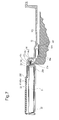
- FIG. 7 is a cross sectional view taken along VII-VII line shown in FIG. 4;
- FIG. 8 is a perspective view of the cover member of the display member
- FIG. 9 is a perspective view of the cover member shown in FIG. 8, viewed from a different angle;
- FIG. 10 is a perspective view of the cover member shown in FIG. 8, viewed from a different angle;
- FIG. 11 is a perspective view of the cover member shown in FIG. 8, viewed from a different angle;
- FIG. 12 is a perspective view of the display member and a frictional member which are components of the digital camera shown in FIGS. 1 through 4;
- FIG. 13 is a perspective view of the display member and the frictional member shown in FIG. 12 with the frictional member fitted into an upper knuckle portion of the display member;
- FIG. 14 is a perspective view of the digital camera shown in FIGS. 1 through 4, showing a state where a pivot pin, serving as an element of the structure of the hinge portion of the digital camera, is removed;
- FIG. 15 is a view similar to that of FIG. 14 and illustrates a state where the display member is hinged on a casing of the camera body with the pivot pin;
- FIG. 16 is a perspective view of the camera body of the digital camera shown in FIGS. 3 and 4 with the display member and the cover member of the camera body being removed;
- FIG. 17A is a cross sectional view of a fundamental portion of the hinge portion of the digital camera shown in FIGS. 1 through 4, showing a shape of the flexible PWB shown in FIG. 6 when the display member is in the fully-open position;
- FIG. 17B is a view similar to that of FIG. 17A, showing a shape of the flexible PWB shown in FIG. 7 when the display member is in the fully-close position;
- FIG. 18 is a plan view of the flexible PWB.
- FIGS. 1 through 4 show an embodiment of a digital camera having a hinge portion between a camera body 10 and a flat-panel display member (swingable member) 20 hinged on the camera body (body member) 10 , according to the present invention.
- the camera body 10 and the display member 20 are hereinafter referred to as a body member 10 and a swingable member 20 , respectively, for the sake of expediency.
- the body member 10 is provided with a pair of exterior members: a body casing 10 H and a body cover member 10 C fixed to the body casing 10 H.
- the swingable member 20 is provided with a pair of exterior members: a swingable casing 20 H and a swingable cover member 20 C fixed to the swingable casing 20 H.
- the swingable member 20 is provided between the swingable casing 20 H and the swingable cover member 20 C with an LCD panel 21 .
- the swingable casing 20 H is provided with a rectangular opening 22 through which the LCD panel 21 is exposed to the outside of the swingable member 20 .
- the swingable casing 20 H is provided with a pair of first knuckles (upper and lower knuckles) 23 which are integrally formed with the swingable casing 20 H.
- the pair of first knuckles 23 extend horizontally from a vertical side wall of the swingable casing 20 H with a vertical gap therebetween so that the respective axes are coaxially arranged.
- the body casing 10 H of the body member 10 is provided with a second pair of knuckles (upper and lower knuckles) 12 which are integrally formed with the body casing 10 H.
- the pair of second knuckles 12 extend horizontally from a rear wall of the body casing 10 H with a vertical gap therebetween so that the respective axes are coaxially arranged.
- the upper knuckle 12 is positioned immediately above the upper knuckle 23 while the lower knuckle 12 is positioned immediately below the lower knuckle 23 .
- the pair of first knuckles 23 and the pair of second knuckles 12 are coaxially arranged.
- the upper knuckle of the pair of first knuckles 23 and the upper knuckle of the pair of second knuckles 12 i.e. an upper pair of knuckles, are hinged with a pivot pin (upper pivot pin) 30 which is inserted into respective axial holes of the two upper knuckles from above the upper knuckle of the pair of second knuckles 12 .
- the lower knuckle of the pair of first knuckles 23 and the lower knuckle of the pair of second knuckles 12 are hinged with another pivot pin (lower pivot pin) 30 which is inserted into respective axial holes of the two lower knuckles from below the lower knuckle of the pair of second knuckles 12 .
- the upper pair of knuckles 12 and 23 that are joined to each other by the upper pivot pin 30 and the lower pair of knuckles 12 and 23 that are joined to each other by the lower pivot pin 30 are symmetrically arranged with respect to a horizontal plane extending through a center point therebetween.
- a frictional member 31 is fitted into an axial hole 23 a of each knuckle 23 of the swingable member 20 before the upper and lower pivot pins 30 are inserted into the axial holes 23 a of the pair of first knuckles 23 , respectively.
- the lower frictional member 31 which is fitted into the axial hole 23 a of the lower knuckle 23 of the swingable member 20 , is not shown in FIGS. 12 and 13.
- Each frictional member 31 is made of a metal leaf spring which is bent to have the shape of a substantially hollow triangular tube.
- each of three side walls 31 a constituting the metal leaf spring of each frictional member 31 is slightly curved inwards so as to come into pressing contact with a cylindrical shaft portion 30 a (see FIG. 14) of the associated pivot pin 30 when the cylindrical shaft portion 30 a is inserted into the frictional member 31 .
- the axial hole 23 a of each knuckle 23 has a substantially triangular cross section corresponding to the shape of each frictional member 31 . This structure prevents each frictional member 31 from rotating in the axial hole 23 a of the associated knuckle 23 .
- each knuckle 12 of the body member 10 has an axial hole 12 b into which the shaft portion 30 a of the associated pivot pin 30 is inserted.
- the axial hole 12 b of each knuckle 12 has a circular cross section, the diameter of which is substantially identical to the diameter of the shaft portion 30 a of each pivot pin 30 .
- Each pivot pin 30 is provided at an end of the shaft portion 30 a with a set of two radial projections 30 b extending radially outwards in opposite directions (see FIG. 14).
- Each knuckle 12 of the body member 10 is provided with a set of two stop grooves 12 a into which the set of two radial projections 30 b of the associated pivot pin 30 are fitted, respectively, when the shaft portion 30 a of the pivot pin 30 is inserted into the axial hole 12 a.
- the swingable member 20 is provided between the pair of first knuckles 23 with a pair of flexible-PWB fixing portions 24 (see FIG. 12), while the body member 10 is provided between the pair of flexible-PWB fixing portions 24 with a flexible-PWB insertion portion 14 (see FIGS. 6,7, 14 and 15 ).
- the pair of flexible-PWB fixing portions 24 is substantially coaxial with the pair of first knuckles 23 , and each flexible-PWB fixing portion 24 consists of a pair of cylindrical halves 24 a and 24 b integrally formed with the associated knuckle 23 and the swingable cover member 20 C, respectively.
- each flexible-PWB fixing portion 24 is hollow.
- Each of the respective ends of the cylindrical halves 24 a and 24 b of each flexible-PWB fixing portion 24 which are engaged with each other when the swingable cover member 20 C and the swingable casing 20 H are properly fixed to each other, is formed as an engaging stepped portion 24 c so that the ends of the cylindrical halves 24 a and 24 b can be securely engaged with each other.
- the pair of flexible-PWB fixing portions 24 and the flexible-PWB insertion portion 14 constitute a guiding structure.
- the flexible-PWB insertion portion 14 of the body member 10 is substantially coaxial with the pair of second knuckles 12 , and consists of a pair of cylindrical halves 14 a and 14 b formed integral with the body casing 10 H and the body cover member 10 C, respectively. Between the cylindrical halves 14 a and 14 b is formed an axial space, i.e., the flexible-PWB insertion portion 14 is hollow. In FIGS. 5 and 16, the cylindrical half portion 14 a appears as a protrusion.
- the swingable cover member 20 C is provided with an opening 25 (see FIGS. 9 and 11) into which the half portion 14 b of the body cover member 10 C is allowed to enter.
- Each of the respective ends of the cylindrical halves 14 a and 14 b of the flexible-PWB insertion portion 14 which are engaged with each other when the body cover member 10 C and the body casing 10 H are correctly fixed to each other, is formed as an engaging stepped portion 14 c so that the ends of the cylindrical halves 14 a and 14 b can be securely engaged with each other.
- the present embodiment of the digital camera is provided with a flexible PWB (flexible printed wiring board) 40 .
- the flexible PWB 40 is provided at one end thereof with a substantially rectangular flat portion 40 a which lies on a rear surface of the LCD panel 21 that is positioned in the swingable member 20 , and is further provided with a wide-width portion 40 b and a narrow-width portion 40 c.
- the wide-width portion 40 b extends from an edge of the flat portion 40 a to be positioned in the pair of flexible-PWB fixing portions 24 , while the narrow-width portion 40 c extends from the wide-width portion 40 b to be positioned in the flexible-PWB insertion portion 14 .
- the wide-width portion 40 b is provided with a rectangular clearance hole 40 d through which the cylindrical half 14 a of the body casing 10 H and a deviation prevention projection 26 projecting from the swingable casing 20 H pass.
- the narrow-width portion 40 c is drawn into the body member 10 so that the end of the narrow-width portion 40 c, i.e. the other end 40 f (see FIGS.
- the narrow-width portion 40 c is bent twice to form two bending portions 40 e (see FIGS. 5 through 7) in the body member 10 .
- the swingable casing 20 H and the swingable cover member 20 C are provided with a bending/guiding portion 27 a and a bending/guiding portion 27 b which are in contact with front and rear surfaces of the wide-width portion 40 b of the flexible PWB 40 , respectively, to define a bending portion of the flexible PWB 40 when the body member 10 and the swingable member 20 rotate relative to each other (see FIGS. 6 and 7). As shown in FIGS.
- the two bending/guiding portions 27 a and 27 b are different from each other in shape and location to bend the flexible PWB 40 (specifically, the narrow-width portion 40 c ) at different positions X and Y thereon when the body member 10 and the swingable member 20 rotate relative to each other.
- “Z” designates a fixed point (reference point) which does not move relative to the swingable member 20 , and the positions X and Y are at predetermined positions from the fixed point Z.
- the flat portion 40 a of the flexible PWB 40 together with the LCD panel 21 is accommodated in the swingable casing 20 H, and at the same time, the wide-width portion 40 b is placed between the pair of first knuckles 23 with the cylindrical half 14 a of the body cover member 10 C and the deviation prevention projection 26 of the swingable casing 20 H penetrating the wide-width portion 40 b through the clearance hole 40 d of the wide-width portion 40 b.
- the narrow-width portion 40 c is drawn into the body member 10 via the flexible-PWB insertion portion 14 .
- the end 40 f of the narrow-width portion 40 c is connected to the connector 15 after the narrow-width portion 40 c is bent twice to form the two bending portions 40 e in the body member 10 .
- the swingable cover member 20 C is fixed to the swingable casing 20 H so that the engaging stepped portions 24 c of the cylindrical halves 24 a and 24 b are engaged with each other to complete the pair of flexible-PWB fixing portions 24 .
- the operation of fixing the flexible PWB 40 to the digital camera is substantially complete.
- the body cover member 10 C is fixed to the body casing 10 H so that the half portion 14 b of the body cover member 10 C is engaged with the half portion 14 a of the body casing 10 H via the opening 25 . This completes the flexible-PWB insertion portion 14 .
- the wide-width portion 40 b of the flexible PWB 40 (the rectangular flat portion 40 a of the flexible PWB 40 being positioned within the swingable member 20 ) is substantially fixed to the pair of flexible-PWB fixing portions 24 while the narrow-width portion 40 c of the flexible PWB 40 is drawn into the body member 10 via the flexible-PWB insertion portion 14 in the hinge portion formed between the body member 10 and the swingable member 20 .
- a movement of the flexible PWB 40 which is caused by a rotational movement of one of the body member 10 and the swingable member 20 relative to the other is absorbed by the bending portions 40 e of the narrow-width portion 40 c of the flexible PWB 40 since the bending portions 40 e are inside the body member 10 .
- the bending/guiding portion 27 a and the bending/guiding portion 27 b prevent the flexible PWB 40 from breakage caused by repeated bending of the flexible PWB 40 at the same portion thereof since the bending/guiding portion 27 a and the bending/guiding portion 27 b change the bending position on the flexible PWB 40 (specifically, the narrow-width portion 40 c thereof) between two different states where the swingable member 20 is open and closed, respectively. Furthermore, the flexible PWB 40 is not exposed to the outside of the digital camera through the flexible-PWB insertion portion 14 and the pair of flexible-PWB fixing portions 24 , which gives a high quality appearance to the digital camera.
- a guiding structure guiding a flexible PWB through a hinge portion between a body and a swingable member hinged on the body is achieved, wherein the guiding structure has little play between the flexible PWB and a hinge portion formed between the body and the swingable member without the flexible PWB being exposed to the outside of the hinge portion.
Landscapes
- Engineering & Computer Science (AREA)
- Theoretical Computer Science (AREA)
- Computer Hardware Design (AREA)
- Physics & Mathematics (AREA)
- Human Computer Interaction (AREA)
- General Engineering & Computer Science (AREA)
- General Physics & Mathematics (AREA)
- Mathematical Physics (AREA)
- Computer Networks & Wireless Communication (AREA)
- Microelectronics & Electronic Packaging (AREA)
- Studio Devices (AREA)
- Camera Bodies And Camera Details Or Accessories (AREA)
Abstract
Description
- 1. Field of the Invention
- The present invention relates to a structure which guides a flexible PWB (printed wiring board) through a hinge portion between a body, e.g. a body of a digital camera or a camcorder, and a swingable member, e.g. a flat-panel display, which is hinged on the body.
- 2. Description of the Related Art
- In an electronic device having an opening-and-closing mechanism using a hinge structure for swingably mounting a swingable member relative to a body of the electronic device, one or more lead wires (electrically conductive lead wires) are generally used when electrical signals need to be communicated between the body and the swingable member. A similar electronic device using a flexible PWB instead the lead wires is also known in the art. This conventional device using a flexible PWB is designed based on the technical concept that sufficient play is given between the flexible PWB and a hinge portion formed between the body and the swingable member so that the flexible PWB does not interfere with the swinging operation of the swingable member.
- The present invention provides a structure for guiding a flexible PWB through a hinge portion between a body and a swingable member hinged on the body, wherein the guiding structure has little play between the flexible PWB and a hinge portion formed between the body and the swingable member without the flexible PWB being exposed to the outside of the hinge portion.
- According to an aspect of the present invention, a guiding structure is provided which guides a flexible printed wiring board through a hinge portion between a body member and a swingable member hinged on the body member via a pivot, the guiding structure including a flexible-PWB fixing portion formed on the swingable member to be coaxial with the pivot, and a flexible-PWB insertion portion formed on the body member to be coaxial with the pivot and to be rotatable relative to the flexible-PWB fixing portion. One end of the flexible printed wiring board is positioned inside the swingable member. An intermediate portion of the flexible printed wiring board is drawn into the body member through the flexible-PWB insertion portion after a portion of the intermediate portion is fixed to the flexible-PWB fixing portion. Another end of the flexible printed wiring board is connected to a connector provided inside the body member.
- The flexible printed wiring board can include at least one bending portion, positioned inside the body member between the connector and the flexible-PWB fixing portion, for absorbing a movement of the flexible printed wiring board when the body member and the swingable member rotate relative to each other.
- The pivot can include a pair of pivot pins, the flexible-PWB fixing portion being positioned between the pair of pivot pins.
- It is desirable for the flexible printed wiring board to include a wide-width portion and a narrow-width portion which extend between the swingable member and the flexible-PWB insertion portion via the flexible-PWB fixing portion. The wide-width portion is fixed to the flexible-PWB fixing portion and the narrow-width portion passes through the flexible-PWB insertion portion.
- It is desirable for the wide-width portion to include a hole through which at least a portion of the flexible-PWB insertion portion passes the wide-width portion.
- It is desirable for the flexible-PWB fixing portion to include a pair of cylindrical halves formed on a casing of the swingable member and a cover member of the swingable member, respectively, the cover member being fixed to the casing.
- It is desirable for the flexible-PWB insertion portion to include a pair of cylindrical halves formed on a casing of the body member and a cover member of the body member, respectively, the cover member being fixed to the casing.
- It is desirable for the casing of the swingable member and the cover member of the swingable member to include a first bending/guiding portion and a second bending/guiding portion which are in contact with two sides of the flexible printed wiring board to define a bending portion thereof, respectively. The first bending/guiding portion and the second bending/guiding portion are different from each other in shape and location to bend the flexible printed wiring board at different positions thereon when the swingable member and the body member rotate relative to each other.
- The body member can serves as a body of a digital camera and the swingable member can serves as a display member of the digital camera.
- The hinge portion can include a first knuckle formed on the body member, a second knuckle formed on the swingable member and positioned to be coaxial with the first knuckle, and a pivot extending through the first knuckle and the second knuckle to join the first knuckle and the second knuckle to each other. The flexible-PWB fixing portion is integrally formed with the second knuckle.
- The swingable member can include a display panel to which the one end of the flexible printed wiring board is fixed.
- In another embodiment, a camera having a camera body and a swingable component hinged on the camera body is provided, including a hinge structure having a first knuckle fixed to the camera body and a second knuckle fixed to the swingable component coaxial with the first knuckle, a pivot extending through the first knuckle and the second knuckle to join the first knuckle and the second knuckle to each other, a flexible printed wiring board extending between the camera body and the swingable component, a flexible-PWB fixing portion formed on the swingable component to be coaxial with the pivot, and a flexible-PWB insertion portion formed on the camera body to be coaxial with the pivot and to be rotatable relative to the flexible-PWB fixing portion. One end of the flexible printed wiring board is positioned inside the swingable component. An intermediate portion of the flexible printed wiring board is drawn into the camera body through the flexible-PWB insertion portion after a portion of the intermediate portion is fixed to the flexible-PWB fixing portion. Another end of the flexible printed wiring board is connected to a connector provided in the camera body.
- The present disclosure relates to subject matter contained in Japanese Patent Application No. 2002-111118 (filed on Apr. 12, 2002) which is expressly incorporated herein by reference in its entirety.
- The present invention will be described below in detail with reference to the accompanying drawings in which:
- FIG. 1 is a front perspective view of an embodiment of a digital camera which incorporates a structure guiding a flexible PWB through a hinge portion to which the prevent invention is applied;
- FIG. 2 is a view similar to that of FIG. 1 and illustrates the digital camera with a swingable display member being fully open.
- FIG. 3 is a rear perspective view of the digital camera shown in FIG. 1;
- FIG. 4 is a rear perspective view of the digital camera shown in FIG. 2;
- FIG. 5 is a view similar to that of FIG. 4 and illustrates the digital camera in a state where a cover member of the display member and a cover member of the camera body are removed;
- FIG. 6 is a cross sectional view taken along VI-VI line shown in FIG. 3;
- FIG. 7 is a cross sectional view taken along VII-VII line shown in FIG. 4;
- FIG. 8 is a perspective view of the cover member of the display member;
- FIG. 9 is a perspective view of the cover member shown in FIG. 8, viewed from a different angle;
- FIG. 10 is a perspective view of the cover member shown in FIG. 8, viewed from a different angle;
- FIG. 11 is a perspective view of the cover member shown in FIG. 8, viewed from a different angle;
- FIG. 12 is a perspective view of the display member and a frictional member which are components of the digital camera shown in FIGS. 1 through 4;
- FIG. 13 is a perspective view of the display member and the frictional member shown in FIG. 12 with the frictional member fitted into an upper knuckle portion of the display member;
- FIG. 14 is a perspective view of the digital camera shown in FIGS. 1 through 4, showing a state where a pivot pin, serving as an element of the structure of the hinge portion of the digital camera, is removed;
- FIG. 15 is a view similar to that of FIG. 14 and illustrates a state where the display member is hinged on a casing of the camera body with the pivot pin;
- FIG. 16 is a perspective view of the camera body of the digital camera shown in FIGS. 3 and 4 with the display member and the cover member of the camera body being removed;
- FIG. 17A is a cross sectional view of a fundamental portion of the hinge portion of the digital camera shown in FIGS. 1 through 4, showing a shape of the flexible PWB shown in FIG. 6 when the display member is in the fully-open position;
- FIG. 17B is a view similar to that of FIG. 17A, showing a shape of the flexible PWB shown in FIG. 7 when the display member is in the fully-close position; and
- FIG. 18 is a plan view of the flexible PWB.
- FIGS. 1 through 4 show an embodiment of a digital camera having a hinge portion between a
camera body 10 and a flat-panel display member (swingable member) 20 hinged on the camera body (body member) 10, according to the present invention. Although one of thecamera body 10 and thedisplay member 20 is swingable relative to the other, thecamera body 10 and thedisplay member 20 are hereinafter referred to as abody member 10 and aswingable member 20, respectively, for the sake of expediency. Thebody member 10 is provided with a pair of exterior members: abody casing 10H and abody cover member 10C fixed to thebody casing 10H. Likewise, theswingable member 20 is provided with a pair of exterior members: aswingable casing 20H and aswingable cover member 20C fixed to theswingable casing 20H. - The
swingable member 20 is provided between theswingable casing 20H and theswingable cover member 20C with anLCD panel 21. Theswingable casing 20H is provided with arectangular opening 22 through which theLCD panel 21 is exposed to the outside of theswingable member 20. As shown in FIGS. 12 through 15, theswingable casing 20H is provided with a pair of first knuckles (upper and lower knuckles) 23 which are integrally formed with theswingable casing 20H. The pair offirst knuckles 23 extend horizontally from a vertical side wall of theswingable casing 20H with a vertical gap therebetween so that the respective axes are coaxially arranged. - As clearly shown in FIG. 16, the
body casing 10H of thebody member 10 is provided with a second pair of knuckles (upper and lower knuckles) 12 which are integrally formed with thebody casing 10H. The pair ofsecond knuckles 12 extend horizontally from a rear wall of thebody casing 10H with a vertical gap therebetween so that the respective axes are coaxially arranged. Theupper knuckle 12 is positioned immediately above theupper knuckle 23 while thelower knuckle 12 is positioned immediately below thelower knuckle 23. In a state where theswingable member 20 is correctly hinged on thebody member 10, the pair offirst knuckles 23 and the pair ofsecond knuckles 12 are coaxially arranged. The upper knuckle of the pair offirst knuckles 23 and the upper knuckle of the pair ofsecond knuckles 12, i.e. an upper pair of knuckles, are hinged with a pivot pin (upper pivot pin) 30 which is inserted into respective axial holes of the two upper knuckles from above the upper knuckle of the pair ofsecond knuckles 12. Likewise, the lower knuckle of the pair offirst knuckles 23 and the lower knuckle of the pair ofsecond knuckles 12, i.e. a lower pair of knuckles, are hinged with another pivot pin (lower pivot pin) 30 which is inserted into respective axial holes of the two lower knuckles from below the lower knuckle of the pair ofsecond knuckles 12. The upper pair ofknuckles upper pivot pin 30 and the lower pair ofknuckles lower pivot pin 30 are symmetrically arranged with respect to a horizontal plane extending through a center point therebetween. - As shown in FIGS. 12 and 13, a
frictional member 31 is fitted into anaxial hole 23 a of eachknuckle 23 of theswingable member 20 before the upper and lower pivot pins 30 are inserted into theaxial holes 23 a of the pair offirst knuckles 23, respectively. The lowerfrictional member 31, which is fitted into theaxial hole 23 a of thelower knuckle 23 of theswingable member 20, is not shown in FIGS. 12 and 13. Eachfrictional member 31 is made of a metal leaf spring which is bent to have the shape of a substantially hollow triangular tube. More specifically, each of threeside walls 31 a constituting the metal leaf spring of eachfrictional member 31 is slightly curved inwards so as to come into pressing contact with acylindrical shaft portion 30 a (see FIG. 14) of the associatedpivot pin 30 when thecylindrical shaft portion 30 a is inserted into thefrictional member 31. Theaxial hole 23 a of eachknuckle 23 has a substantially triangular cross section corresponding to the shape of eachfrictional member 31. This structure prevents eachfrictional member 31 from rotating in theaxial hole 23 a of the associatedknuckle 23. At the same time, when each of the threeside walls 31 a of eachfrictional member 31 is resiliently deformed by an insertion of theshaft portion 30 a of the associatedpivot pin 30 into thefrictional member 31, twoparallel ridges 31 b and twoparallel edges 31 b′ are firmly pressed against an inner surface of theknuckle 23 in theaxial hole 23 a with substantially no play between thefrictional member 31 and the inner surface of theknuckle 23. On the other hand, as shown in FIG. 14, eachknuckle 12 of thebody member 10 has anaxial hole 12 b into which theshaft portion 30 a of the associatedpivot pin 30 is inserted. Theaxial hole 12 b of eachknuckle 12 has a circular cross section, the diameter of which is substantially identical to the diameter of theshaft portion 30 a of eachpivot pin 30. - Each
pivot pin 30 is provided at an end of theshaft portion 30 a with a set of tworadial projections 30 b extending radially outwards in opposite directions (see FIG. 14). Eachknuckle 12 of thebody member 10 is provided with a set of twostop grooves 12 a into which the set of tworadial projections 30 b of the associatedpivot pin 30 are fitted, respectively, when theshaft portion 30 a of thepivot pin 30 is inserted into theaxial hole 12 a. - The
swingable member 20 is provided between the pair offirst knuckles 23 with a pair of flexible-PWB fixing portions 24 (see FIG. 12), while thebody member 10 is provided between the pair of flexible-PWB fixing portions 24 with a flexible-PWB insertion portion 14 (see FIGS. 6,7, 14 and 15). The pair of flexible-PWB fixing portions 24 is substantially coaxial with the pair offirst knuckles 23, and each flexible-PWB fixing portion 24 consists of a pair ofcylindrical halves knuckle 23 and theswingable cover member 20C, respectively. Between thecylindrical halves PWB fixing portion 24 is hollow. Each of the respective ends of thecylindrical halves PWB fixing portion 24, which are engaged with each other when theswingable cover member 20C and theswingable casing 20H are properly fixed to each other, is formed as an engaging steppedportion 24 c so that the ends of thecylindrical halves PWB fixing portions 24 and the flexible-PWB insertion portion 14 constitute a guiding structure. - On the other hand, the flexible-
PWB insertion portion 14 of thebody member 10 is substantially coaxial with the pair ofsecond knuckles 12, and consists of a pair ofcylindrical halves body casing 10H and thebody cover member 10C, respectively. Between thecylindrical halves PWB insertion portion 14 is hollow. In FIGS. 5 and 16, thecylindrical half portion 14 a appears as a protrusion. Theswingable cover member 20C is provided with an opening 25 (see FIGS. 9 and 11) into which thehalf portion 14 b of thebody cover member 10C is allowed to enter. Each of the respective ends of thecylindrical halves PWB insertion portion 14, which are engaged with each other when thebody cover member 10C and thebody casing 10H are correctly fixed to each other, is formed as an engaging steppedportion 14 c so that the ends of thecylindrical halves - As shown in FIGS. 5, 6 and 7, the present embodiment of the digital camera is provided with a flexible PWB (flexible printed wiring board) 40. As shown in FIGS. 5 and 18, the
flexible PWB 40 is provided at one end thereof with a substantially rectangularflat portion 40 a which lies on a rear surface of theLCD panel 21 that is positioned in theswingable member 20, and is further provided with a wide-width portion 40 b and a narrow-width portion 40 c. The wide-width portion 40 b extends from an edge of theflat portion 40 a to be positioned in the pair of flexible-PWB fixing portions 24, while the narrow-width portion 40 c extends from the wide-width portion 40 b to be positioned in the flexible-PWB insertion portion 14. The wide-width portion 40 b is provided with arectangular clearance hole 40 d through which thecylindrical half 14 a of thebody casing 10H and adeviation prevention projection 26 projecting from theswingable casing 20H pass. The narrow-width portion 40 c is drawn into thebody member 10 so that the end of the narrow-width portion 40 c, i.e. theother end 40 f (see FIGS. 6 and 7) of theflexible PWB 40, is connected to aconnector 15 provided in thebody member 10. The narrow-width portion 40 c is bent twice to form two bendingportions 40 e (see FIGS. 5 through 7) in thebody member 10. - The
swingable casing 20H and theswingable cover member 20C are provided with a bending/guidingportion 27 a and a bending/guidingportion 27 b which are in contact with front and rear surfaces of the wide-width portion 40 b of theflexible PWB 40, respectively, to define a bending portion of theflexible PWB 40 when thebody member 10 and theswingable member 20 rotate relative to each other (see FIGS. 6 and 7). As shown in FIGS. 17A and 17B, the two bending/guidingportions width portion 40 c) at different positions X and Y thereon when thebody member 10 and theswingable member 20 rotate relative to each other. In FIGS. 17A and 17B, “Z” designates a fixed point (reference point) which does not move relative to theswingable member 20, and the positions X and Y are at predetermined positions from the fixed point Z. - In the above described flexible-PWB guiding structure which guides the
flexible PWB 40 through the hinge portion between thebody member 10 and theswingable member 20, theflat portion 40 a of theflexible PWB 40 together with theLCD panel 21 is accommodated in theswingable casing 20H, and at the same time, the wide-width portion 40 b is placed between the pair offirst knuckles 23 with thecylindrical half 14 a of thebody cover member 10C and thedeviation prevention projection 26 of theswingable casing 20H penetrating the wide-width portion 40 b through theclearance hole 40 d of the wide-width portion 40 b. Moreover, the narrow-width portion 40 c is drawn into thebody member 10 via the flexible-PWB insertion portion 14. Furthermore, theend 40 f of the narrow-width portion 40 c is connected to theconnector 15 after the narrow-width portion 40 c is bent twice to form the two bendingportions 40 e in thebody member 10. - After the narrow-
width portion 40 c is connected to theconnector 15 at theend 40 f, theswingable cover member 20C is fixed to theswingable casing 20H so that the engaging steppedportions 24 c of thecylindrical halves PWB fixing portions 24. At this stage, the operation of fixing theflexible PWB 40 to the digital camera is substantially complete. Thereafter, thebody cover member 10C is fixed to thebody casing 10H so that thehalf portion 14 b of thebody cover member 10C is engaged with thehalf portion 14 a of thebody casing 10H via theopening 25. This completes the flexible-PWB insertion portion 14. - According to the present embodiment of the digital camera assembled in the above described manner, the wide-
width portion 40 b of the flexible PWB 40 (the rectangularflat portion 40 a of theflexible PWB 40 being positioned within the swingable member 20) is substantially fixed to the pair of flexible-PWB fixing portions 24 while the narrow-width portion 40 c of theflexible PWB 40 is drawn into thebody member 10 via the flexible-PWB insertion portion 14 in the hinge portion formed between thebody member 10 and theswingable member 20. Moreover, a movement of theflexible PWB 40 which is caused by a rotational movement of one of thebody member 10 and theswingable member 20 relative to the other is absorbed by the bendingportions 40 e of the narrow-width portion 40 c of theflexible PWB 40 since the bendingportions 40 e are inside thebody member 10. The bending/guidingportion 27 a and the bending/guidingportion 27 b prevent theflexible PWB 40 from breakage caused by repeated bending of theflexible PWB 40 at the same portion thereof since the bending/guidingportion 27 a and the bending/guidingportion 27 b change the bending position on the flexible PWB 40 (specifically, the narrow-width portion 40 c thereof) between two different states where theswingable member 20 is open and closed, respectively. Furthermore, theflexible PWB 40 is not exposed to the outside of the digital camera through the flexible-PWB insertion portion 14 and the pair of flexible-PWB fixing portions 24, which gives a high quality appearance to the digital camera. - As can be understood from the above description, a guiding structure guiding a flexible PWB through a hinge portion between a body and a swingable member hinged on the body is achieved, wherein the guiding structure has little play between the flexible PWB and a hinge portion formed between the body and the swingable member without the flexible PWB being exposed to the outside of the hinge portion.
- Obvious changes may be made in the specific embodiment of the present invention described herein, such modifications being within the spirit and scope of the invention claimed. It is indicated that all matter contained herein is illustrative and does not limit the scope of the present invention.
Claims (12)
Applications Claiming Priority (2)
| Application Number | Priority Date | Filing Date | Title |
|---|---|---|---|
| JP2002111118A JP4153717B2 (en) | 2002-04-12 | 2002-04-12 | FPC guide structure of hinge part |
| JP2002-111118 | 2002-04-12 |
Publications (2)
| Publication Number | Publication Date |
|---|---|
| US20030193783A1 true US20030193783A1 (en) | 2003-10-16 |
| US6853545B2 US6853545B2 (en) | 2005-02-08 |
Family
ID=28786641
Family Applications (1)
| Application Number | Title | Priority Date | Filing Date |
|---|---|---|---|
| US10/407,265 Expired - Fee Related US6853545B2 (en) | 2002-04-12 | 2003-04-07 | Structure for guiding flexible printed wiring board through a hinge portion between a body and a swingable member |
Country Status (2)
| Country | Link |
|---|---|
| US (1) | US6853545B2 (en) |
| JP (1) | JP4153717B2 (en) |
Cited By (4)
| Publication number | Priority date | Publication date | Assignee | Title |
|---|---|---|---|---|
| US20070161292A1 (en) * | 2004-01-23 | 2007-07-12 | Sony Corporation | Turning hinge mechanism and image pick up device |
| US20150147081A1 (en) * | 2011-07-15 | 2015-05-28 | Sharp Kabushiki Kaisha | Electronic apparatus having pivotable support member for supporting electric circuit board |
| CN105763769A (en) * | 2014-12-18 | 2016-07-13 | 富泰华工业(深圳)有限公司 | Camera and electronic device therewith |
| CN110572590A (en) * | 2019-06-28 | 2019-12-13 | RealMe重庆移动通信有限公司 | Camera assembly and electronic equipment |
Families Citing this family (2)
| Publication number | Priority date | Publication date | Assignee | Title |
|---|---|---|---|---|
| US9261904B2 (en) * | 2013-09-16 | 2016-02-16 | Top Victory Investments Limited | Point of sale system |
| JP6238771B2 (en) * | 2014-01-30 | 2017-11-29 | キヤノン株式会社 | Electronics |
Citations (3)
| Publication number | Priority date | Publication date | Assignee | Title |
|---|---|---|---|---|
| US5790193A (en) * | 1995-11-22 | 1998-08-04 | Eastman Kodak Company | Accessory module for an electronic camera |
| US6353529B1 (en) * | 1998-11-12 | 2002-03-05 | Thomas Cies | Z-configuration structure for computers, scanners, and communications and video devices |
| US6587151B1 (en) * | 1998-08-26 | 2003-07-01 | International Business Machines Corporation | Video camera integration on a portable computer |
-
2002
- 2002-04-12 JP JP2002111118A patent/JP4153717B2/en not_active Expired - Fee Related
-
2003
- 2003-04-07 US US10/407,265 patent/US6853545B2/en not_active Expired - Fee Related
Patent Citations (3)
| Publication number | Priority date | Publication date | Assignee | Title |
|---|---|---|---|---|
| US5790193A (en) * | 1995-11-22 | 1998-08-04 | Eastman Kodak Company | Accessory module for an electronic camera |
| US6587151B1 (en) * | 1998-08-26 | 2003-07-01 | International Business Machines Corporation | Video camera integration on a portable computer |
| US6353529B1 (en) * | 1998-11-12 | 2002-03-05 | Thomas Cies | Z-configuration structure for computers, scanners, and communications and video devices |
Cited By (6)
| Publication number | Priority date | Publication date | Assignee | Title |
|---|---|---|---|---|
| US20070161292A1 (en) * | 2004-01-23 | 2007-07-12 | Sony Corporation | Turning hinge mechanism and image pick up device |
| US7619682B2 (en) * | 2004-01-23 | 2009-11-17 | Sony Corporation | Turning hinge mechanism and image pick up device |
| US20150147081A1 (en) * | 2011-07-15 | 2015-05-28 | Sharp Kabushiki Kaisha | Electronic apparatus having pivotable support member for supporting electric circuit board |
| US9170551B2 (en) * | 2011-07-15 | 2015-10-27 | Sharp Kabushiki Kaisha | Electronic apparatus having pivotable support member for supporting electric circuit board |
| CN105763769A (en) * | 2014-12-18 | 2016-07-13 | 富泰华工业(深圳)有限公司 | Camera and electronic device therewith |
| CN110572590A (en) * | 2019-06-28 | 2019-12-13 | RealMe重庆移动通信有限公司 | Camera assembly and electronic equipment |
Also Published As
| Publication number | Publication date |
|---|---|
| JP2003302687A (en) | 2003-10-24 |
| JP4153717B2 (en) | 2008-09-24 |
| US6853545B2 (en) | 2005-02-08 |
Similar Documents
| Publication | Publication Date | Title |
|---|---|---|
| JP3196018B2 (en) | Relay connector with shield mechanism | |
| KR100421370B1 (en) | Fpc connecting structure for electronic equipment and fpc thereof | |
| JP3295808B2 (en) | Cable connector | |
| KR100532135B1 (en) | Housing for flexibility cable connector | |
| KR20050036599A (en) | Portable computer | |
| US6091601A (en) | Slide snap-in flex cable bobbin assembly for a portable computer | |
| US7094084B2 (en) | Electrical connector assembly for mobile terminal | |
| US7178200B2 (en) | Hinge structure | |
| US6853545B2 (en) | Structure for guiding flexible printed wiring board through a hinge portion between a body and a swingable member | |
| US20110256744A1 (en) | Electrical connector having dust-proof device with self-driven arrangement | |
| KR20020065702A (en) | Folder type mobile communication terminal | |
| US6692297B2 (en) | Rotatable card connector assembly | |
| JP2003158355A (en) | Connection structure of flexible printed board and electronic apparatus | |
| US12235689B2 (en) | Cable arrangement mechanism | |
| JP2549003B2 (en) | Notebook electronic device | |
| US20050059283A1 (en) | Portable electronic device and external module thereof | |
| WO2008004756A1 (en) | An fpc/ffc connector for a flexible cable | |
| KR20040108762A (en) | Electrical connector with shutter member | |
| US7042533B2 (en) | LCD module connecting mechanism comprising an arm connected to a frame by inserting a hook of the arm through first and second openings formed on a lateral surface of the frame | |
| JP2007043379A (en) | Folding electronic apparatus | |
| JP4708092B2 (en) | Electronics | |
| JPH0451516Y2 (en) | ||
| JP5114035B2 (en) | Hinge structure and folding portable terminal using the same | |
| KR100513837B1 (en) | Fitting nail for flexibility cable connector | |
| JP3123421B2 (en) | Lever connector |
Legal Events
| Date | Code | Title | Description |
|---|---|---|---|
| AS | Assignment |
Owner name: PENTAX CORPORATION, JAPAN Free format text: ASSIGNMENT OF ASSIGNORS INTEREST;ASSIGNORS:KOSAKO, KOSEI;ENDO, KEN;REEL/FRAME:013939/0518 Effective date: 20030402 |
|
| FEPP | Fee payment procedure |
Free format text: PAYOR NUMBER ASSIGNED (ORIGINAL EVENT CODE: ASPN); ENTITY STATUS OF PATENT OWNER: LARGE ENTITY |
|
| FPAY | Fee payment |
Year of fee payment: 4 |
|
| AS | Assignment |
Owner name: HOYA CORPORATION, JAPAN Free format text: MERGER;ASSIGNOR:PENTAX CORPORATION;REEL/FRAME:026970/0554 Effective date: 20080331 |
|
| AS | Assignment |
Owner name: PENTAX RICOH IMAGING COMPANY, LTD., JAPAN Free format text: CORPORATE SPLIT;ASSIGNOR:HOYA CORPORATION;REEL/FRAME:027315/0115 Effective date: 20111003 |
|
| FPAY | Fee payment |
Year of fee payment: 8 |
|
| REMI | Maintenance fee reminder mailed | ||
| LAPS | Lapse for failure to pay maintenance fees | ||
| STCH | Information on status: patent discontinuation |
Free format text: PATENT EXPIRED DUE TO NONPAYMENT OF MAINTENANCE FEES UNDER 37 CFR 1.362 |
|
| STCH | Information on status: patent discontinuation |
Free format text: PATENT EXPIRED DUE TO NONPAYMENT OF MAINTENANCE FEES UNDER 37 CFR 1.362 |
|
| FP | Lapsed due to failure to pay maintenance fee |
Effective date: 20170208 |