US20030193384A1 - Square sleeve in combination with a drum core for electrical appliance - Google Patents
Square sleeve in combination with a drum core for electrical appliance Download PDFInfo
- Publication number
- US20030193384A1 US20030193384A1 US10/118,976 US11897602A US2003193384A1 US 20030193384 A1 US20030193384 A1 US 20030193384A1 US 11897602 A US11897602 A US 11897602A US 2003193384 A1 US2003193384 A1 US 2003193384A1
- Authority
- US
- United States
- Prior art keywords
- combination
- square sleeve
- drum core
- receiving area
- contacting portions
- Prior art date
- Legal status (The legal status is an assumption and is not a legal conclusion. Google has not performed a legal analysis and makes no representation as to the accuracy of the status listed.)
- Abandoned
Links
Images


Classifications
-
- H—ELECTRICITY
- H01—ELECTRIC ELEMENTS
- H01F—MAGNETS; INDUCTANCES; TRANSFORMERS; SELECTION OF MATERIALS FOR THEIR MAGNETIC PROPERTIES
- H01F17/00—Fixed inductances of the signal type
- H01F17/04—Fixed inductances of the signal type with magnetic core
- H01F17/045—Fixed inductances of the signal type with magnetic core with core of cylindric geometry and coil wound along its longitudinal axis, i.e. rod or drum core
-
- H—ELECTRICITY
- H01—ELECTRIC ELEMENTS
- H01F—MAGNETS; INDUCTANCES; TRANSFORMERS; SELECTION OF MATERIALS FOR THEIR MAGNETIC PROPERTIES
- H01F27/00—Details of transformers or inductances, in general
- H01F27/28—Coils; Windings; Conductive connections
- H01F27/29—Terminals; Tapping arrangements for signal inductances
- H01F27/292—Surface mounted devices
Definitions
- the present invention relates to a combination of a square sleeve and a drum core, and more particularly to a combination of a square sleeve and a drum core for electrical appliance.
- the drum core is mounted in the receiving area in the square sleeve so as to eliminate the unnecessary process to reduce cost and enhance the inductance of the combination.
- FIG. 6 a conventional combination 9 of a square sleeve and a drum core is shown.
- the combination has a rectangular base 91 made of plastic, a magnetic ring 94 on top of the base 91 , multiple metallic contacts 92 extending out of the base 91 so as to form feet 93 outside the base 91 .
- the base 91 is able to be mounted on a circuit board (not shown).
- a drum core 95 is provided in the magnetic ring 94 and has a coil winding area 96 defined in a mediate portion of the drum core 95 so that a coil 97 is able to be wound around the drum core 95 in the coil winding area 96 .
- Two distal ends 971 of the coil 97 is connected to contacts 92 oppositely arranged in the base 91 .
- a second embodiment 9 A of the conventional combination of the square sleeve and the drum core is shown and has a base 91 A with multiple L shaped extensions (not numbered), a magnetic ring 94 A on top of the base 91 A and feet 93 A arranged outside the base 91 A so as to mount the base 91 A on a circuit board (not shown).
- a drum core 95 A is provided in the magnetic ring 94 A and has a coil winding area 96 A defined in a mediate portion of the drum core 95 A so that a coil 97 A is able to be wound around the drum core 95 A in the coil winding area 96 A.
- Two distal ends 971 A of the coil 97 A is connected to feet 93 A oppositely arranged in the base 91 A.
- the present invention intends to provide an improved combination of a square sleeve and a drum core to mitigate or obviate the aforementioned problems.
- the primary objective of the invention is to a combination of a square sleeve and a drum core for electrical appliance, e.g., cellular phone, stereo, computer, etc.
- the drum core is mounted in the receiving area in the square sleeve so as to eliminate the unnecessary process to reduce cost and enhance the inductance of the combination.
- Another objective of the invention is to provide a combination of a square sleeve and a drum core, which is able to enhance the inductance performance and to reduce the space occupied.
- FIG. 1 is a perspective view of the combination of a square sleeve and a drum core of the present invention
- FIG. 2 is an exploded perspective view of the combination of the present invention
- FIG. 3 is an exploded perspective view showing that coil is wound around the drum core of the present invention
- FIG. 4 is a schematic view showing the application of the combination of the present invention.
- FIG. 5 is a schematic view showing the combination is mounted on a circuit board
- FIG. 6 is a perspective view of a conventional combination of a square sleeve and a drum core
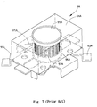
- FIG. 7 is a perspective view of still a conventional combination of a square sleeve and a drum core.
- the combination of a square sleeve and a drum core includes:
- a square sleeve 2 which is made of a magnetic material and has a receiving area 21 defined therein, wherein in this embodiment, the receiving area 21 is a through hole;
- each of the at least two contacting portions 22 has a guiding recess 221 extending toward the receiving area 21 from a corner of the square sleeve 2 ;
- a drum core 3 which is received in the receiving area 21 and has a coil winding area 31 .
- a coil 1 is wound around the coil winding area 31 and two distal ends 11 of the coil 1 are received in two opposite guiding recesses 221 . Because there are four guiding recesses 221 , the two distal ends 11 of the coil 1 are able to be received in either pair of two opposite guiding recesses 221 such that each one of the distal ends 11 has different directional feature so as to enhance the convenience when in assembly. Then the drum core 3 is placed in the receiving area 21 . Thereafter, the two contacting portions 22 are electrically connected to a circuit board 12 .
- the two connecting portions 22 are formed on the bottom face 23 of the square sleeve 2 and the drum core 3 is placed in the receiving area 21 so that there is no requirement to separately assemble the magnetic ring and the base as does the conventional structure. Furthermore, the dimension of the combination of the present invention is reduced so as to increase the convenience in assembly. Still, due to the material for making the square sleeve 2 being magnetic material so that after assembly, the combination is able to increase he inductance performance.
- the combination of the square sleeve and the drum core is able to reduce its dimension, which is quite useful when engaged with the circuit board, and to increase its inductance performance when mounted on a circuit board.
Landscapes
- Engineering & Computer Science (AREA)
- Power Engineering (AREA)
- Microelectronics & Electronic Packaging (AREA)
- Coils Or Transformers For Communication (AREA)
Abstract
A square sleeve is made of a magnetic material and has a receiving area defined therein. At least two contacting portions are formed on a bottom face of the square sleeve and on opposite sides of the receiving area. The drum core is received in the receiving area and has a coil winding area for winding a coil having two distal ends which are electrically connected to the at least two contacting portions.
Description
- 1. Field of the Invention
- The present invention relates to a combination of a square sleeve and a drum core, and more particularly to a combination of a square sleeve and a drum core for electrical appliance. The drum core is mounted in the receiving area in the square sleeve so as to eliminate the unnecessary process to reduce cost and enhance the inductance of the combination.
- 2. Description of Related Art
- With reference to FIG. 6, a
conventional combination 9 of a square sleeve and a drum core is shown. The combination has arectangular base 91 made of plastic, amagnetic ring 94 on top of thebase 91, multiplemetallic contacts 92 extending out of thebase 91 so as to formfeet 93 outside thebase 91. With thefeet 93, thebase 91 is able to be mounted on a circuit board (not shown). Adrum core 95 is provided in themagnetic ring 94 and has acoil winding area 96 defined in a mediate portion of thedrum core 95 so that acoil 97 is able to be wound around thedrum core 95 in thecoil winding area 96. Twodistal ends 971 of thecoil 97 is connected tocontacts 92 oppositely arranged in thebase 91. - With reference to FIG. 7, a
second embodiment 9A of the conventional combination of the square sleeve and the drum core is shown and has abase 91A with multiple L shaped extensions (not numbered), amagnetic ring 94A on top of thebase 91A andfeet 93A arranged outside thebase 91A so as to mount thebase 91A on a circuit board (not shown). Adrum core 95A is provided in themagnetic ring 94A and has acoil winding area 96A defined in a mediate portion of thedrum core 95A so that acoil 97A is able to be wound around thedrum core 95A in thecoil winding area 96A. Twodistal ends 971A of thecoil 97A is connected tofeet 93A oppositely arranged in thebase 91A. - The separation mounting process for the
magnetic ring feet conventional combination - To overcome the shortcomings, the present invention intends to provide an improved combination of a square sleeve and a drum core to mitigate or obviate the aforementioned problems.
- The primary objective of the invention is to a combination of a square sleeve and a drum core for electrical appliance, e.g., cellular phone, stereo, computer, etc. The drum core is mounted in the receiving area in the square sleeve so as to eliminate the unnecessary process to reduce cost and enhance the inductance of the combination.
- Another objective of the invention is to provide a combination of a square sleeve and a drum core, which is able to enhance the inductance performance and to reduce the space occupied.
- Other objects, advantages and novel features of the invention will become more apparent from the following detailed description when taken in conjunction with the accompanying drawings.
- FIG. 1 is a perspective view of the combination of a square sleeve and a drum core of the present invention;
- FIG. 2 is an exploded perspective view of the combination of the present invention;
- FIG. 3 is an exploded perspective view showing that coil is wound around the drum core of the present invention;
- FIG. 4 is a schematic view showing the application of the combination of the present invention;
- FIG. 5 is a schematic view showing the combination is mounted on a circuit board;
- FIG. 6 is a perspective view of a conventional combination of a square sleeve and a drum core; and
- FIG. 7 is a perspective view of still a conventional combination of a square sleeve and a drum core.
- With reference to FIG. 1 and FIG. 2, the combination of a square sleeve and a drum core includes:
- a
square sleeve 2 which is made of a magnetic material and has areceiving area 21 defined therein, wherein in this embodiment, thereceiving area 21 is a through hole; - at least two contacting
portions 22 which are formed on abottom face 23 of thesquare sleeve 2 and on opposite sides of thereceiving area 21, wherein the at least two contactingportions 22 are formed on thebottom face 23 of thesquare sleeve 2 by metalized process, each of the at least two contactingportions 22 has a guidingrecess 221 extending toward thereceiving area 21 from a corner of thesquare sleeve 2; and - a
drum core 3 which is received in thereceiving area 21 and has acoil winding area 31. - With reference to FIGS. 3 to 5, when assembly of the combination of the present invention is required, a
coil 1 is wound around thecoil winding area 31 and twodistal ends 11 of thecoil 1 are received in two opposite guidingrecesses 221. Because there are four guidingrecesses 221, the twodistal ends 11 of thecoil 1 are able to be received in either pair of two opposite guidingrecesses 221 such that each one of thedistal ends 11 has different directional feature so as to enhance the convenience when in assembly. Then thedrum core 3 is placed in thereceiving area 21. Thereafter, the two contactingportions 22 are electrically connected to acircuit board 12. - It is to be noted that the two connecting
portions 22 are formed on thebottom face 23 of thesquare sleeve 2 and thedrum core 3 is placed in thereceiving area 21 so that there is no requirement to separately assemble the magnetic ring and the base as does the conventional structure. Furthermore, the dimension of the combination of the present invention is reduced so as to increase the convenience in assembly. Still, due to the material for making thesquare sleeve 2 being magnetic material so that after assembly, the combination is able to increase he inductance performance. - Although the foregoing description describes that there are two contacting
portions 22, two additional contactingportions 22 may also be added to achieve the required objective. - In conclusion, the combination of the square sleeve and the drum core is able to reduce its dimension, which is quite useful when engaged with the circuit board, and to increase its inductance performance when mounted on a circuit board.
- Even though numerous characteristics and advantages of the present invention have been set forth in the foregoing description, together with details of the structure and function of the invention, the disclosure is illustrative only, and changes may be made in detail, especially in matters of shape, size, and arrangement of parts within the principles of the invention to the full extent indicated by the broad general meaning of the terms in which the appended claims are expressed.
Claims (6)
1. In a combination of a square sleeve and a drum core, wherein the improvements comprise:
the square sleeve is made of a magnetic material and has a receiving area defined therein,
at least two contacting portions are formed on a bottom face of the square sleeve and on opposite sides of the receiving area; and
the drum core is received in the receiving area and has a coil winding area for winding a coil having two distal ends which are electrically connected to the at least two contacting portions.
2. The combination as claimed in claim 1 , wherein each of the at least two contacting portions has at least one guiding recess extending toward the receiving area from a corner of the square sleeve.
3. The combination as claimed in claim 2 , wherein the at least two contacting portions are mounted on opposite sides of the square sleeve.
4. the combination as claimed in claim 3 , wherein four guiding recesses are defined in each corner of the square sleeve to extend toward the receiving area.
5. The combination as claimed in claim 1 , wherein the at least two contacting portions are formed on the bottom face of the square sleeve by metalized process.
6. The combination as claimed in claim 1 , wherein the receiving area is a through hole.
Priority Applications (1)
| Application Number | Priority Date | Filing Date | Title |
|---|---|---|---|
| US10/118,976 US20030193384A1 (en) | 2002-04-10 | 2002-04-10 | Square sleeve in combination with a drum core for electrical appliance |
Applications Claiming Priority (1)
| Application Number | Priority Date | Filing Date | Title |
|---|---|---|---|
| US10/118,976 US20030193384A1 (en) | 2002-04-10 | 2002-04-10 | Square sleeve in combination with a drum core for electrical appliance |
Publications (1)
| Publication Number | Publication Date |
|---|---|
| US20030193384A1 true US20030193384A1 (en) | 2003-10-16 |
Family
ID=28789895
Family Applications (1)
| Application Number | Title | Priority Date | Filing Date |
|---|---|---|---|
| US10/118,976 Abandoned US20030193384A1 (en) | 2002-04-10 | 2002-04-10 | Square sleeve in combination with a drum core for electrical appliance |
Country Status (1)
| Country | Link |
|---|---|
| US (1) | US20030193384A1 (en) |
Cited By (3)
| Publication number | Priority date | Publication date | Assignee | Title |
|---|---|---|---|---|
| USD671510S1 (en) * | 2010-03-18 | 2012-11-27 | Maruwa Co., Ltd. | Surface-mounted coil |
| USD671511S1 (en) * | 2011-01-17 | 2012-11-27 | Maruwa Co., Ltd. | Surface-mounted coil |
| US20180158597A1 (en) * | 2016-12-02 | 2018-06-07 | Cyntec Co., Ltd. | Transformer |
Citations (2)
| Publication number | Priority date | Publication date | Assignee | Title |
|---|---|---|---|---|
| US3585553A (en) * | 1970-04-16 | 1971-06-15 | Us Army | Microminiature leadless inductance element |
| US4314221A (en) * | 1979-09-17 | 1982-02-02 | Tdk Electronics Co., Ltd. | Inductance device |
-
2002
- 2002-04-10 US US10/118,976 patent/US20030193384A1/en not_active Abandoned
Patent Citations (2)
| Publication number | Priority date | Publication date | Assignee | Title |
|---|---|---|---|---|
| US3585553A (en) * | 1970-04-16 | 1971-06-15 | Us Army | Microminiature leadless inductance element |
| US4314221A (en) * | 1979-09-17 | 1982-02-02 | Tdk Electronics Co., Ltd. | Inductance device |
Cited By (4)
| Publication number | Priority date | Publication date | Assignee | Title |
|---|---|---|---|---|
| USD671510S1 (en) * | 2010-03-18 | 2012-11-27 | Maruwa Co., Ltd. | Surface-mounted coil |
| USD671511S1 (en) * | 2011-01-17 | 2012-11-27 | Maruwa Co., Ltd. | Surface-mounted coil |
| US20180158597A1 (en) * | 2016-12-02 | 2018-06-07 | Cyntec Co., Ltd. | Transformer |
| US10340074B2 (en) * | 2016-12-02 | 2019-07-02 | Cyntec Co., Ltd. | Transformer |
Similar Documents
| Publication | Publication Date | Title |
|---|---|---|
| JP4783183B2 (en) | Inductor | |
| US9647340B2 (en) | Three-axis antenna | |
| JP2010268306A (en) | Coil antenna | |
| US8878640B2 (en) | Common-mode choke coil | |
| US10170819B2 (en) | RFID antenna structure | |
| US20020017972A1 (en) | Low profile inductor | |
| US20080278274A1 (en) | Combined transformer | |
| ATE348416T1 (en) | MINIATURE INDUCTIVE COMPONENT, IN PARTICULAR ANTENNA | |
| EP1763044B1 (en) | Inductor | |
| JP2007080922A5 (en) | ||
| US20030193384A1 (en) | Square sleeve in combination with a drum core for electrical appliance | |
| US6788181B2 (en) | Chassis of surface mounted inductor | |
| US20030201860A1 (en) | Ferrite sleeve base with drum core for SMT inductors | |
| JP4716054B2 (en) | Horizontal coil parts | |
| US6606060B2 (en) | Chip antenna | |
| US20020164903A1 (en) | Interference free connector | |
| US20060267716A1 (en) | Inductor and base thereof | |
| US20040027223A1 (en) | Connecting pin structure for a transformer core | |
| US20060197644A1 (en) | Flat inductor and the method for forming the same | |
| JP2004241678A (en) | Surface-mounting coil and its manufacturing method | |
| US20050174000A1 (en) | Motor case | |
| US20050141742A1 (en) | Induction coil for a hearing aid | |
| KR200312344Y1 (en) | Choke coil | |
| US20080238598A1 (en) | Inductor | |
| US20050180093A1 (en) | Non-reciprocal circuit element |
Legal Events
| Date | Code | Title | Description |
|---|---|---|---|
| STPP | Information on status: patent application and granting procedure in general |
Free format text: FINAL REJECTION MAILED |
|
| STCB | Information on status: application discontinuation |
Free format text: ABANDONED -- FAILURE TO RESPOND TO AN OFFICE ACTION |
|
| STCB | Information on status: application discontinuation |
Free format text: ABANDONED -- FAILURE TO RESPOND TO AN OFFICE ACTION |