US20030192982A1 - Servo-controlled traverse mechanism for winder - Google Patents
Servo-controlled traverse mechanism for winder Download PDFInfo
- Publication number
- US20030192982A1 US20030192982A1 US10/120,183 US12018302A US2003192982A1 US 20030192982 A1 US20030192982 A1 US 20030192982A1 US 12018302 A US12018302 A US 12018302A US 2003192982 A1 US2003192982 A1 US 2003192982A1
- Authority
- US
- United States
- Prior art keywords
- strand
- servo
- spindle
- motor
- traverse
- Prior art date
- Legal status (The legal status is an assumption and is not a legal conclusion. Google has not performed a legal analysis and makes no representation as to the accuracy of the status listed.)
- Granted
Links
- 230000007246 mechanism Effects 0.000 title claims abstract description 23
- 238000004804 winding Methods 0.000 claims abstract description 35
- 238000000034 method Methods 0.000 claims description 10
- 239000004753 textile Substances 0.000 claims description 8
- 230000002093 peripheral effect Effects 0.000 claims description 5
- 230000000295 complement effect Effects 0.000 claims description 4
- 241001589086 Bellapiscis medius Species 0.000 claims description 2
- 229910001220 stainless steel Inorganic materials 0.000 claims description 2
- 238000010586 diagram Methods 0.000 description 4
- 230000000712 assembly Effects 0.000 description 2
- 238000000429 assembly Methods 0.000 description 2
- 238000012423 maintenance Methods 0.000 description 2
- 238000012545 processing Methods 0.000 description 2
- 238000012546 transfer Methods 0.000 description 2
- 239000010963 304 stainless steel Substances 0.000 description 1
- 239000004677 Nylon Substances 0.000 description 1
- 229910000589 SAE 304 stainless steel Inorganic materials 0.000 description 1
- 230000001133 acceleration Effects 0.000 description 1
- 238000012937 correction Methods 0.000 description 1
- 230000007423 decrease Effects 0.000 description 1
- 238000013461 design Methods 0.000 description 1
- 238000001125 extrusion Methods 0.000 description 1
- 238000004519 manufacturing process Methods 0.000 description 1
- 229920001778 nylon Polymers 0.000 description 1
- 229920002635 polyurethane Polymers 0.000 description 1
- 239000004814 polyurethane Substances 0.000 description 1
- 229920002994 synthetic fiber Polymers 0.000 description 1
Images


Classifications
-
- B—PERFORMING OPERATIONS; TRANSPORTING
- B65—CONVEYING; PACKING; STORING; HANDLING THIN OR FILAMENTARY MATERIAL
- B65H—HANDLING THIN OR FILAMENTARY MATERIAL, e.g. SHEETS, WEBS, CABLES
- B65H54/00—Winding, coiling, or depositing filamentary material
- B65H54/02—Winding and traversing material on to reels, bobbins, tubes, or like package cores or formers
- B65H54/28—Traversing devices; Package-shaping arrangements
- B65H54/2821—Traversing devices driven by belts or chains
-
- B—PERFORMING OPERATIONS; TRANSPORTING
- B65—CONVEYING; PACKING; STORING; HANDLING THIN OR FILAMENTARY MATERIAL
- B65H—HANDLING THIN OR FILAMENTARY MATERIAL, e.g. SHEETS, WEBS, CABLES
- B65H54/00—Winding, coiling, or depositing filamentary material
- B65H54/02—Winding and traversing material on to reels, bobbins, tubes, or like package cores or formers
- B65H54/28—Traversing devices; Package-shaping arrangements
- B65H54/2833—Traversing devices driven by electromagnetic means
-
- B—PERFORMING OPERATIONS; TRANSPORTING
- B65—CONVEYING; PACKING; STORING; HANDLING THIN OR FILAMENTARY MATERIAL
- B65H—HANDLING THIN OR FILAMENTARY MATERIAL, e.g. SHEETS, WEBS, CABLES
- B65H54/00—Winding, coiling, or depositing filamentary material
- B65H54/02—Winding and traversing material on to reels, bobbins, tubes, or like package cores or formers
- B65H54/28—Traversing devices; Package-shaping arrangements
- B65H54/2884—Microprocessor-controlled traversing devices in so far the control is not special to one of the traversing devices of groups B65H54/2803 - B65H54/325 or group B65H54/38
-
- B—PERFORMING OPERATIONS; TRANSPORTING
- B65—CONVEYING; PACKING; STORING; HANDLING THIN OR FILAMENTARY MATERIAL
- B65H—HANDLING THIN OR FILAMENTARY MATERIAL, e.g. SHEETS, WEBS, CABLES
- B65H2701/00—Handled material; Storage means
- B65H2701/30—Handled filamentary material
- B65H2701/31—Textiles threads or artificial strands of filaments
Definitions
- This invention relates to a servo-controlled traverse mechanism for a winder, particularly a textile winder used to wind textile strands onto tubular support packages for further processing.
- the invention relates generally to textile strands such as yarns, filaments or tapes of natural or synthetic materials (all referred to as “yarns”) and is particularly concerned with the traversing mechanism necessary for laying the yarn onto the package in a precise, regular pattern.
- the traditional mechanism for producing such traversing motion includes a grooved scroll or drum which either engages the yarn directly or drives a yarn guide, causing it move in a reciprocating, traversing motion.
- Such mechanisms are, however, limited in their speed of operation, are subject to mechanical. wear, and must be replaced when changing the pattern by which the yarn is to be applied to the package.
- Winders for which the invention is suitable include back-winders, reminders and spoolers, among others. While the system is adaptable to new machines, the particular embodiment disclosed herein is explained by way of example with reference to a Leesona 861 rewinder to which the system has been retrofitted. The system is likewise adaptable to wind both straight-sided cylindrical and tapered packages.
- Winding systems are as old as the mechanical processing of yarn. There are numerous types of winders for differing purposes. Recently developed methods of yarn production such as continuous filament extrusion and texturizing have further emphasized this demand for winders having higher speeds of operation.
- One form of traversing mechanism which has been proposed for operation at such high speeds includes slot-like yarn guides mounted on closely spaced driving members moving in opposite directions across the traverse so that the yarn is carried from one end of the traverse to the other by a guide of one member and is then transferred to a guide of the other member so as to be carried back in opposite direction.
- the wind ratio refers to the number of rotations of the spindle on which the yarn package is positioned for each back-and-forth passage of the yarn traverse. For example, a wind ratio of 6 means that approximately six winds are placed on the package during each back-and-forth passage of the yarn traverse along the length of the package, i.e, three in each direction.
- Traverse length refers to the length along the spindle of the yarn applied to the package.
- the “gain” refers to the minute amount of incremental progression in the placement of the yarn on the package during each traverse to prevent successive wraps of yarn from being placed directly on top of the previous wraps of yarn.
- Vander Groef U.S. Pat. No. 5,499,775 Patent discloses a winder for winding a wire cable with a programmable traverse control.
- the system takes into account the unique problems of winding wire which is subject to kinking and twisting.
- a “figure 8” package is produced which forms a “hole” at a point where no cross-overs occur during the wire winding process.
- the stoke of the traverse is slightly out phase with the rotation of the wire spool so that the cross-overs progress around the spool.
- the number of cross-overs never advances a full 360 degrees around the spindle.
- the radial “hole” is formed at the point where no cross-overs are made.
- the machine is operated by conventional motors.
- the present system provides an electronic means of winding textile yarns which permits the various parameters to be controlled by software instead of by hardware.
- changes in wind ratios and traverse length can be made by changing the inputs into the system.
- a very efficient and effective traverse mechanism is provided capable of operating at the high speeds made possible by the electronic control of the winding process.
- a winding machine for winding a strand onto a tubular support to form a strand package, and comprising a spindle on which the tubular support is mounted for rotation therewith, a motor for rotating the spindle, and a reciprocating traverse mechanism, including a strand guide, for guiding the strand onto the tubular support at a predetermined traverse stroke and wind ratio.
- the traverse mechanism comprises a servo-motor for selectively starting and stopping reciprocating movement of the strand guide in accordance with the predetermined traverse stroke and wind ratio; and a programmable servo-controller for accepting data inputs reflecting the desired traverse stroke and wind ratio and for outputting data to the servo-motor reflecting the desired traverse stroke and wind ratio.
- the spindle is rotated at a constant strand winding speed.
- a speed sensor is provided for detecting the surface speed of the strand package.
- a spindle motor speed controller accepts a signal output from the speed sensor representing the surface speed of the strand package and outputs a signal representing the surface speed of the strand package. The signal is sent to the spindle motor speed controller for slowing the rpm of the spindle as the diameter of the strand package increases to maintain a constant spindle surface winding speed, and to the servo-controller for slowing the traverse servo-motor in synchronization with the slowing of the rpm of the strand package and thus maintaining a constant wind ratio.
- the traverse mechanism comprises a drive cable pulley carried by the servo-motor for rotation therewith, a driven cable pulley positioned in spaced-apart relation to the driven pulley, and a drive cable having first and second opposed ends attached to and carrying the strand guide.
- the drive cable extends around the drive cable pulley and driven cable pulley for being reciprocated by the starting and stopping reciprocating movement of the servo-motor under control of the servo-controller for moving the strand guide back-and-forth along the length of the spindle as the strand is wound onto the tubular support.
- said drive cable comprises a core member around which is wound a spiral member in a predetermined angle and spacing to define raised driving convolutions on the surface of the core.
- the drive cable pulley and said driven cable pulley are each are provided with a plurality of regularly-spaced helical grooves on an outer peripheral driving surface thereof complementary with the driving convolutions on the surface of the core of the drive cable.
- the core member comprises a bundle of stranded stainless steel wire encapsulated in a flexible elastomeric jacket.
- said strand support is a constant diameter tube, and said strand comprises a textile yarn.
- said strand support is a cone, and said strand comprises a textile yarn.
- said winding machine comprises a machine selected from the group consisting of a rewinder, take-up winder, and two-for-one twister.
- An embodiment of the method of winding a strand onto a tubular support to form a strand package comprises the steps of providing a spindle on the which the tubular support is mounted for rotation therewith, a motor for rotating the spindle, and a reciprocating traverse mechanism, including a strand guide, for guiding the strand onto the tubular support at a predetermined traverse stroke and wind ratio.
- Data inputs are generated reflecting the desired predetermined traverse stroke and wind ratio.
- Data is output to a servo-motor driving the strand guide, said data reflecting the desired traverse stroke and wind ratio.
- the servo-motor is selectively started and stopped under the control of a servo-controller and thus the reciprocating movement of the strand guide in accordance with the predetermined stroke and wind ratio.
- the method includes the steps of rotating the spindle at a constant strand winding speed; detecting the surface speed of the strand package, and outputting a signal representing the surface speed of the strand package to a servo-controller.
- a signal is output representing the surface speed of the strand package for slowing the rpm of the spindle as the diameter of the strand package increases to maintaining a constant spindle surface speed, and to the servo-controller for slowing the traverse servo-motor in synchronization with the slowing of the rpm of the strand package and thus maintaining a constant wind ratio.
- the step of reciprocating the traverse mechanism comprises the steps of providing a drive cable pulley carried by the servo-motor for rotation therewith, providing a driven cable pulley positioned in spaced-apart relation to the driven pulley, and providing a drive cable having first and second opposed ends attached to and carrying the strand guide, said drive cable being passed around the drive cable pulley and driven cable pulley for being moved in opposite directions by the starting and stopping reciprocating movement of the servo-motor under control of the servo-controller for moving the strand guide back-and-forth along the length of the spindle as the strand is wound onto the tubular support.
- the drive cable comprises a core member around which is wound a spiral member in a precise predetermined angle and spacing to define raised driving convolutions on the surface of the core.
- the drive cable pulley and said driven cable pulley are each are provided with a plurality of regularly-spaced helical grooves on an outer peripheral driving surface thereof complementary to the raised driving convolutions on the drive cable.
- FIGS. 1 and 2 are perspective views of a winder station equipped with the servo traverse assembly according to a preferred embodiment of the invention
- FIG. 3 is a perspective view of a servo traverse assembly according to a preferred embodiment of the present invention.
- FIG. 4 is a second perspective view of a servo traverse assembly according to a preferred embodiment of the present invention.
- FIG. 5 is an exploded perspective view of a servo traverse assembly according to a preferred embodiment of the present invention.
- FIG. 6 is a front elevation of the servo traverse assembly
- FIG. 7 is a top plan view of the servo traverse assembly
- FIG. 8 is a perspective view of a winder station equipped with the servo traverse assembly shown in FIGS. 1 - 3 in the winding position from a direction generally opposite the position shown in FIG. 5;
- FIG. 9 is a fragmentary perspective view of a multiple station winder equipped with servo traverse assemblies according to a preferred embodiment of the invention.
- FIG. 10 is a schematic block diagram illustrating operation of the servo traverse assembly.
- FIGS. 11, 12 and 13 flow diagrams of the servo traverse assembly illustrating startup, initialization and traverse program functions.
- FIG. 1 a servo traverse assembly according to the present invention is illustrated in FIG. 1 and shown generally at reference numeral 10 .
- the assembly 10 is mounted on a base 11 carried by a conventional machine frame.
- a take-up spindle 12 is mounted for movement between a position, FIG. 1, where a yarn package “P” is donned and doffed, and a winding position, FIG. 2.
- a roll 13 rides on the surface of the package “P” to control pressure during the winding process.
- Roll 13 also has a 6-tooth pulse wheel (not shown) mounted on its end which provides pulses to a magnetic device which outputs a signal to the spindle motor 52 which drives spindle 12 .
- a handle 15 is used to move the spindle 12 into and out of the two positions shown in FIGS. 1 and 2. These features are conventional and therefore not further described.
- yarn is wound onto the package “P” by a traverse mechanism positioned in a housing 20 and driven by a servo-motor 40 .
- the housing 20 is positioned alongside the spindle 12 in the ordinary manner and permits yarn from a supply package, not shown, to be wound onto the package “P.”
- the servo traverse assembly 10 is capable of winding yarn in accordance with any pattern or wind configuration, and the resulting “P” package is visually indistinguishable from packages wound by conventional means.
- the invention is usable on either a constant yarn speed system whereby, as the diameter of the package “P” increases the rpm of the spindle 12 decreases, or on a constant spindle speed system.
- the traverse mechanism is best shown in FIGS. 3 - 7 .
- a motor pulley bracket 21 carries the servo-motor 40 on one end.
- the servo-motor 40 drives a drive cable 22 to which is mounted a cable traverse guide 23 .
- the cable traverse guide 23 is carried by a traverse guide rail 26 which extends along the length of the housing 20 .
- the drive cable 22 is mounted for reciprocating motion on driven pulley assemblies 28 , 29 and 30 driven by a drive pulley 31 mounted on the output shaft of the servo-motor 40 .
- the servo-motor 40 is an Allen-Bradley Part No. 193521, with a peak torque of 33.7 in./lbs.
- the drive cable is a synchromesh cable such as disclosed in U.S. Pat. No. 4,846,772, and has a helical driving surface to move the traverse at high speed. Prior art uses of this cable include driving the printing head of printers and plotters.
- the helical driving surface is formed by a helically-applied polyurethane strand around a nylon-coated core of 304 stainless steel.
- One suitable product is made by SDP Inch.
- the pulleys 28 , 29 , 30 and 31 each have a peripheral surface with helical groove segments therein which mate with the strand.
- the drive cable 22 is particularly suited for high-speed reciprocation around sharp angles, and is both highly precise and reliable.
- the cable 22 has a very low mass and thus low inertia. This allows very rapid reciprocations without cable deformation.
- the servo traverse assembly 10 is positioned to be adjacent to the drive roll 13 in position to apply the yarn in a controlled manner directly to the surface of the rotating package “P”.
- a plurality of servo traverse assembles 10 will typically be positioned adjacent each other on a winder frame in a conventional manner for simultaneously winding multiple packages “P”.
- the servo traverse assembly 10 is started and stopped in a conventional manner by a power switch 50 .
- Power is delivered to a spindle motor speed controller 51 and to a spindle motor 52 .
- the desired winding speed is input through a yarn speed input device 53 .
- the spindle 12 is rotated through a belt and pulley arrangement in accordance with the prior art.
- the spindle speed of the spindle 12 is detected by an encoder 55 , which outputs a signal to a servo-controller 56 .
- the servo-controller 56 outputs a signal to the servo-motor 40 which drives the drive cable 22 in coordination with the spindle 12 .
- Feedback from the servo-motor 40 through a feedback loop results in a very precise real-time speed correction. As a result, yarn is applied to the package “P” in a very precise and at very high speed.
- the servo-motor 40 includes an encoder which outputs a feedback signal indicative of the speed of the motor 40 .
- Inputs including traverse length, wind ratio, acceleration angle and deceleration angle are input through an input keypad 58 , for example, an Allen-Bradley Panelview 300.
- yarn can be wound at up to 1000 yards per minute onto a tube mounted on a 3 ⁇ fraction (11/16) ⁇ inch tube holder, at between a 3.5 and 6.5 wind ratio with a 10 inch traverse stroke.
- Tapered packages are capable of being wound, as well as the more conventional tubular packages.
- the servo-controller 56 that controls the servo-motor 40 also execute the motion control program, eliminating the need for an external motion controller. Interface to the winder is by means of a standard serial port.
- FIGS. 11, 12 and 13 flow diagrams for the startup, initialization and traverse functions are illustrated in standard flow diagram format.
Landscapes
- Physics & Mathematics (AREA)
- Electromagnetism (AREA)
- Engineering & Computer Science (AREA)
- Microelectronics & Electronic Packaging (AREA)
- Winding Filamentary Materials (AREA)
Abstract
A winding machine for winding a strand onto a tubular support to form a strand package, and including a spindle on the which the tubular support is mounted for rotation therewith. A motor is provided for rotating the spindle. A reciprocating traverse mechanism, including a strand guide, guides the strand onto the tubular support at a predetermined traverse stroke and wind ratio. The traverse mechanism includes servo-motor for selectively starting and stopping reciprocating movement of the strand guide in accordance with the predetermined traverse stroke and wind ratio, and a programmable servo-controller accepts data inputs reflecting the desired traverse stroke and wind ratio and outputting data to the servo-motor reflecting the desired traverse stroke and wind ratio.
Description
- This invention relates to a servo-controlled traverse mechanism for a winder, particularly a textile winder used to wind textile strands onto tubular support packages for further processing. The invention relates generally to textile strands such as yarns, filaments or tapes of natural or synthetic materials (all referred to as “yarns”) and is particularly concerned with the traversing mechanism necessary for laying the yarn onto the package in a precise, regular pattern. The traditional mechanism for producing such traversing motion includes a grooved scroll or drum which either engages the yarn directly or drives a yarn guide, causing it move in a reciprocating, traversing motion. Such mechanisms are, however, limited in their speed of operation, are subject to mechanical. wear, and must be replaced when changing the pattern by which the yarn is to be applied to the package.
- Winders for which the invention is suitable include back-winders, reminders and spoolers, among others. While the system is adaptable to new machines, the particular embodiment disclosed herein is explained by way of example with reference to a Leesona 861 rewinder to which the system has been retrofitted. The system is likewise adaptable to wind both straight-sided cylindrical and tapered packages.
- Winding systems are as old as the mechanical processing of yarn. There are numerous types of winders for differing purposes. Recently developed methods of yarn production such as continuous filament extrusion and texturizing have further emphasized this demand for winders having higher speeds of operation. One form of traversing mechanism which has been proposed for operation at such high speeds includes slot-like yarn guides mounted on closely spaced driving members moving in opposite directions across the traverse so that the yarn is carried from one end of the traverse to the other by a guide of one member and is then transferred to a guide of the other member so as to be carried back in opposite direction. This avoids the problem arising from the inertia of the yarn guides or other parts being caused to move first in one direction and then the other with a very abrupt reversal at the end of each traverse. The transfer of the yarn from one guide to another presents its own problems and proposals have been made to include a deflector arrangement at each end of the field of traverse for assisting the transfer of the yarn from one guide to the other. Such traversing mechanisms must be used in conjunction with a package support roller on the winder so that the yarn passes from the yarn guide to a nip between the package and the support roller and is thus maintained under control over this part of its travel.
- Other mechanical solutions have been proposed, but all contain inherent limitations arising out of the use of fixed design and machined parts specific to a particular wind.
- There are several basic parameters which determine the pattern by which the yarn is applied to the package. These are the wind ratio, traverse length and gain. The wind ratio refers to the number of rotations of the spindle on which the yarn package is positioned for each back-and-forth passage of the yarn traverse. For example, a wind ratio of 6 means that approximately six winds are placed on the package during each back-and-forth passage of the yarn traverse along the length of the package, i.e, three in each direction. Traverse length refers to the length along the spindle of the yarn applied to the package. The “gain” refers to the minute amount of incremental progression in the placement of the yarn on the package during each traverse to prevent successive wraps of yarn from being placed directly on top of the previous wraps of yarn.
- These parameters are well understood in the art. Moreover, efforts have been made to adapt these concepts to electronic systems. For example, the Vander Groef U.S. Pat. No. 5,499,775 Patent discloses a winder for winding a wire cable with a programmable traverse control. The system takes into account the unique problems of winding wire which is subject to kinking and twisting. A “figure 8” package is produced which forms a “hole” at a point where no cross-overs occur during the wire winding process. The stoke of the traverse is slightly out phase with the rotation of the wire spool so that the cross-overs progress around the spool. The number of cross-overs never advances a full 360 degrees around the spindle. Thus, the radial “hole” is formed at the point where no cross-overs are made. The machine is operated by conventional motors.
- The present system provides an electronic means of winding textile yarns which permits the various parameters to be controlled by software instead of by hardware. Thus, changes in wind ratios and traverse length can be made by changing the inputs into the system. In addition, a very efficient and effective traverse mechanism is provided capable of operating at the high speeds made possible by the electronic control of the winding process.
- Therefore, it is an object of the invention to provide a winder which utilizes a programmable electronic controller to control various input parameters.
- It is another object of the invention to provide a winder which uses a servo-motor to reciprocate a mechanical traverse mechanism efficiently and at high speed.
- It is another object of the invention to provide a winder which uses a cable with a helical driving surface to move the traverse at high speed.
- It is another object of the invention to provide a winder which utilizes a servo system which both runs the traverse motor and also executes the motion control application which defines the traverse parameters.
- It is another object of the invention to provide a winder which is suitable for being retrofitted to a wide variety of existing mechanically-operated winders.
- It is another object of the invention to provide a winder which improves machine flexibility, speeds machine setup changes, reduces maintenance costs and reduces machine noise and parts wear.
- These and other objects of the present invention are achieved in the preferred embodiments disclosed below by providing a winding machine for winding a strand onto a tubular support to form a strand package, and comprising a spindle on which the tubular support is mounted for rotation therewith, a motor for rotating the spindle, and a reciprocating traverse mechanism, including a strand guide, for guiding the strand onto the tubular support at a predetermined traverse stroke and wind ratio. The traverse mechanism comprises a servo-motor for selectively starting and stopping reciprocating movement of the strand guide in accordance with the predetermined traverse stroke and wind ratio; and a programmable servo-controller for accepting data inputs reflecting the desired traverse stroke and wind ratio and for outputting data to the servo-motor reflecting the desired traverse stroke and wind ratio.
- According to one preferred embodiment of the invention, the spindle is rotated at a constant strand winding speed. A speed sensor is provided for detecting the surface speed of the strand package. A spindle motor speed controller accepts a signal output from the speed sensor representing the surface speed of the strand package and outputs a signal representing the surface speed of the strand package. The signal is sent to the spindle motor speed controller for slowing the rpm of the spindle as the diameter of the strand package increases to maintain a constant spindle surface winding speed, and to the servo-controller for slowing the traverse servo-motor in synchronization with the slowing of the rpm of the strand package and thus maintaining a constant wind ratio.
- According to another preferred embodiment of the invention, the traverse mechanism comprises a drive cable pulley carried by the servo-motor for rotation therewith, a driven cable pulley positioned in spaced-apart relation to the driven pulley, and a drive cable having first and second opposed ends attached to and carrying the strand guide. The drive cable extends around the drive cable pulley and driven cable pulley for being reciprocated by the starting and stopping reciprocating movement of the servo-motor under control of the servo-controller for moving the strand guide back-and-forth along the length of the spindle as the strand is wound onto the tubular support.
- According to another preferred embodiment of the invention, said drive cable comprises a core member around which is wound a spiral member in a predetermined angle and spacing to define raised driving convolutions on the surface of the core. The drive cable pulley and said driven cable pulley are each are provided with a plurality of regularly-spaced helical grooves on an outer peripheral driving surface thereof complementary with the driving convolutions on the surface of the core of the drive cable.
- According to yet another preferred embodiment of the invention, the core member comprises a bundle of stranded stainless steel wire encapsulated in a flexible elastomeric jacket.
- According to yet another preferred embodiment of the invention, said strand support is a constant diameter tube, and said strand comprises a textile yarn.
- According to yet another preferred embodiment of the invention, said strand support is a cone, and said strand comprises a textile yarn.
- According to yet another preferred embodiment of the invention, said winding machine comprises a machine selected from the group consisting of a rewinder, take-up winder, and two-for-one twister.
- An embodiment of the method of winding a strand onto a tubular support to form a strand package according to the invention comprises the steps of providing a spindle on the which the tubular support is mounted for rotation therewith, a motor for rotating the spindle, and a reciprocating traverse mechanism, including a strand guide, for guiding the strand onto the tubular support at a predetermined traverse stroke and wind ratio. Data inputs are generated reflecting the desired predetermined traverse stroke and wind ratio. Data is output to a servo-motor driving the strand guide, said data reflecting the desired traverse stroke and wind ratio. The servo-motor is selectively started and stopped under the control of a servo-controller and thus the reciprocating movement of the strand guide in accordance with the predetermined stroke and wind ratio.
- According to yet another preferred embodiment of the invention, the method includes the steps of rotating the spindle at a constant strand winding speed; detecting the surface speed of the strand package, and outputting a signal representing the surface speed of the strand package to a servo-controller. A signal is output representing the surface speed of the strand package for slowing the rpm of the spindle as the diameter of the strand package increases to maintaining a constant spindle surface speed, and to the servo-controller for slowing the traverse servo-motor in synchronization with the slowing of the rpm of the strand package and thus maintaining a constant wind ratio.
- According to yet another preferred embodiment of the invention, the step of reciprocating the traverse mechanism comprises the steps of providing a drive cable pulley carried by the servo-motor for rotation therewith, providing a driven cable pulley positioned in spaced-apart relation to the driven pulley, and providing a drive cable having first and second opposed ends attached to and carrying the strand guide, said drive cable being passed around the drive cable pulley and driven cable pulley for being moved in opposite directions by the starting and stopping reciprocating movement of the servo-motor under control of the servo-controller for moving the strand guide back-and-forth along the length of the spindle as the strand is wound onto the tubular support.
- According to yet another preferred embodiment of the invention, the drive cable comprises a core member around which is wound a spiral member in a precise predetermined angle and spacing to define raised driving convolutions on the surface of the core. The drive cable pulley and said driven cable pulley are each are provided with a plurality of regularly-spaced helical grooves on an outer peripheral driving surface thereof complementary to the raised driving convolutions on the drive cable.
- Some of the objects of the invention have been set forth above. Other objects and advantages of the invention will appear as the invention proceeds when taken in conjunction with the following drawings, in which:
- FIGS. 1 and 2 are perspective views of a winder station equipped with the servo traverse assembly according to a preferred embodiment of the invention;
- FIG. 3 is a perspective view of a servo traverse assembly according to a preferred embodiment of the present invention;
- FIG. 4 is a second perspective view of a servo traverse assembly according to a preferred embodiment of the present invention;
- FIG. 5 is an exploded perspective view of a servo traverse assembly according to a preferred embodiment of the present invention;
- FIG. 6 is a front elevation of the servo traverse assembly;
- FIG. 7 is a top plan view of the servo traverse assembly;
- FIG. 8 is a perspective view of a winder station equipped with the servo traverse assembly shown in FIGS. 1-3 in the winding position from a direction generally opposite the position shown in FIG. 5;
- FIG. 9 is a fragmentary perspective view of a multiple station winder equipped with servo traverse assemblies according to a preferred embodiment of the invention;
- FIG. 10 is a schematic block diagram illustrating operation of the servo traverse assembly; and
- FIGS. 11, 12 and 13 flow diagrams of the servo traverse assembly illustrating startup, initialization and traverse program functions.
- Referring now specifically to the drawings, a servo traverse assembly according to the present invention is illustrated in FIG. 1 and shown generally at
reference numeral 10. Theassembly 10 is mounted on a base 11 carried by a conventional machine frame. A take-upspindle 12 is mounted for movement between a position, FIG. 1, where a yarn package “P” is donned and doffed, and a winding position, FIG. 2. Aroll 13 rides on the surface of the package “P” to control pressure during the winding process.Roll 13 also has a 6-tooth pulse wheel (not shown) mounted on its end which provides pulses to a magnetic device which outputs a signal to thespindle motor 52 which drivesspindle 12. - A
handle 15 is used to move thespindle 12 into and out of the two positions shown in FIGS. 1 and 2. These features are conventional and therefore not further described. - In accordance with the invention, yarn is wound onto the package “P” by a traverse mechanism positioned in a
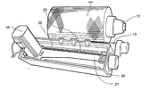
housing 20 and driven by a servo-motor 40. Thehousing 20 is positioned alongside thespindle 12 in the ordinary manner and permits yarn from a supply package, not shown, to be wound onto the package “P.” Theservo traverse assembly 10 is capable of winding yarn in accordance with any pattern or wind configuration, and the resulting “P” package is visually indistinguishable from packages wound by conventional means. The invention is usable on either a constant yarn speed system whereby, as the diameter of the package “P” increases the rpm of thespindle 12 decreases, or on a constant spindle speed system. - The traverse mechanism is best shown in FIGS. 3-7. A
motor pulley bracket 21 carries the servo-motor 40 on one end. The servo-motor 40 drives adrive cable 22 to which is mounted acable traverse guide 23. Thecable traverse guide 23 is carried by atraverse guide rail 26 which extends along the length of thehousing 20. Thedrive cable 22 is mounted for reciprocating motion on drivenpulley assemblies drive pulley 31 mounted on the output shaft of the servo-motor 40. - The servo-
motor 40 according to the preferred embodiment disclosed herein is an Allen-Bradley Part No. 193521, with a peak torque of 33.7 in./lbs. The drive cable is a synchromesh cable such as disclosed in U.S. Pat. No. 4,846,772, and has a helical driving surface to move the traverse at high speed. Prior art uses of this cable include driving the printing head of printers and plotters. The helical driving surface is formed by a helically-applied polyurethane strand around a nylon-coated core of 304 stainless steel. One suitable product is made by SDP Inch. Thepulleys drive cable 22 is particularly suited for high-speed reciprocation around sharp angles, and is both highly precise and reliable. Thecable 22 has a very low mass and thus low inertia. This allows very rapid reciprocations without cable deformation. - As is best shown in FIG. 5, opposite ends of the
drive cable 22 are attached to opposite ends of thecable traverse guide 23. One suitable traverse length is 10 inches, but other longer or shorter traverse lengths may be used. - Further details of the cable and pulley arrangement are shown in FIGS. 6 and 7.
- As is shown in FIG. 8, the
servo traverse assembly 10 is positioned to be adjacent to thedrive roll 13 in position to apply the yarn in a controlled manner directly to the surface of the rotating package “P”. As is shown in FIG. 9, a plurality of servo traverse assembles 10 will typically be positioned adjacent each other on a winder frame in a conventional manner for simultaneously winding multiple packages “P”. - Referring now to FIG. 10, operation of the
servo traverse assembly 10 is described. The servo traverse assembly is started and stopped in a conventional manner by apower switch 50. Power is delivered to a spindlemotor speed controller 51 and to aspindle motor 52. The desired winding speed is input through a yarnspeed input device 53. Thespindle 12 is rotated through a belt and pulley arrangement in accordance with the prior art. - The spindle speed of the
spindle 12 is detected by anencoder 55, which outputs a signal to a servo-controller 56. The servo-controller 56 outputs a signal to the servo-motor 40 which drives thedrive cable 22 in coordination with thespindle 12. Feedback from the servo-motor 40 through a feedback loop results in a very precise real-time speed correction. As a result, yarn is applied to the package “P” in a very precise and at very high speed. - The servo-
motor 40 includes an encoder which outputs a feedback signal indicative of the speed of themotor 40. Inputs, including traverse length, wind ratio, acceleration angle and deceleration angle are input through aninput keypad 58, for example, an Allen-Bradley Panelview 300. - In a preferred application, yarn can be wound at up to 1000 yards per minute onto a tube mounted on a 3{fraction (11/16)} inch tube holder, at between a 3.5 and 6.5 wind ratio with a 10 inch traverse stroke.
- The servo-
controller 56 is preferably an Allen-Bradley Motion Control System, including an Allen-Bradley PCL-5 programmable logic controller. Electronic control of the system allows for infinite variation of the traverse length and wind ratio, providing improved machine flexibility, faster machine setup changes, reduced maintenance, reduced machine noise, and the ability to modify older, obsolete machines. - Tapered packages are capable of being wound, as well as the more conventional tubular packages. The servo-
controller 56 that controls the servo-motor 40 also execute the motion control program, eliminating the need for an external motion controller. Interface to the winder is by means of a standard serial port. - Referring now to FIGS. 11, 12 and 13, flow diagrams for the startup, initialization and traverse functions are illustrated in standard flow diagram format.
- A servo traverse assembly is described above. Various details of the invention may be changed without departing from its scope. Furthermore, the foregoing description of the preferred embodiment of the invention and the best mode for practicing the invention are provided for the purpose of illustration only and not for the purpose of limitation—the invention being defined by the claims.
Claims (12)
1. A winding machine for winding a strand onto a tubular support to form a strand package, and comprising:
(a) a spindle on the which the tubular support is mounted for rotation therewith;
(b) a motor for rotating the spindle;
(c) a reciprocating traverse mechanism, including a strand guide, for guiding the strand onto the tubular support at a predetermined traverse stroke and wind ratio, said traverse mechanism comprising:
(i) a servo-motor for selectively starting and stopping reciprocating movement of the strand guide in accordance with the predetermined traverse stroke and wind ratio; and
(ii) a programmable servo-controller for accepting data inputs reflecting the desired traverse stroke and wind ratio and for outputting data to the servo-motor reflecting the desired traverse stroke and wind ratio.
2. A winding machine according to claim 1 , wherein the spindle is rotated at a constant strand winding speed, and including a speed sensor for detecting the surface speed of the strand package, a spindle motor speed controller for accepting a signal output from the speed sensor representing the surface speed of the strand package and outputting a signal representing the surface speed of the strand package:
(a) to the spindle motor speed controller for slowing the rpm of the spindle as the diameter of the strand package increases to maintain a constant spindle surface winding speed; and
(b) to the servo-controller for slowing the traverse servo-motor in synchronization with the slowing of the rpm of the strand package and thus maintaining a constant wind ratio.
3. A winding machine according to claim 1 or 2, wherein the traverse mechanism comprises:
(a) a drive cable pulley carried by the servo-motor for rotation therewith;
(b) a driven cable pulley positioned in spaced-apart relation to the driven pulley;
(c) a drive cable having first and second opposed ends attached to and carrying the strand guide, said drive cable extending around the drive cable pulley and driven cable pulley for being reciprocated by the starting and stopping reciprocating movement of the servo-motor under control of the servo-controller for moving the strand guide back-and-forth along the length of the spindle as the strand is wound onto the tubular support.
4. A winding machine according to claim 3 , wherein said drive cable comprises a core member around which is wound a spiral member in a predetermined angle and spacing to define raised driving convolutions on the surface of the core, and further wherein said drive cable pulley and said driven cable pulley are each are provided with a plurality of regularly-spaced helical grooves on an outer peripheral driving surface thereof complementary with the driving convolutions on the surface of the core of the drive cable.
5. A winding machine according to claim 4 , wherein said core member comprises a bundle of stranded stainless steel wire encapsulated in a flexible elastomeric jacket.
6. A winding machine according to claim 1 , wherein said strand support is a constant diameter tube, and said strand comprises a textile yarn.
7. A winding machine according to claim 1 , wherein said strand support is a cone, and said strand comprises a textile yarn.
8. A winding machine according to claim 1 , 2, 3, 4, 5, 6 or 7, wherein said winding machine comprises a machine selected from the group consisting of a rewinder, take-up winder, and two-for-one twister.
9. A method of winding a strand onto a tubular support to form a strand package, and comprising the steps of:
(a) providing a spindle on the which the tubular support is mounted for rotation therewith, a motor for rotating the spindle, and a reciprocating traverse mechanism, including a strand guide, for guiding the strand onto the tubular support at a predetermined traverse stroke and wind ratio;
(b) generating data inputs reflecting the desired predetermined traverse stroke and wind ratio;
(c) outputting data to a servo-motor driving the strand guide, said data reflecting the desired traverse stroke and wind ratio;
(d) selectively starting and stopping the servo-motor and thus the reciprocating movement of the strand guide in accordance with the predetermined stroke and wind ratio.
10. A method according to claim 9 , including the steps of:
(a) rotating the spindle at a constant strand winding speed,
(b) detecting the surface speed of the strand package;
(c) outputting a signal representing the surface speed of the strand package to a servo-controller and outputting a signal representing the surface speed of the strand package:
(i) for slowing the rpm of the spindle as the diameter of the strand package increases to maintaining a constant spindle surface speed; and
(ii) to the servo-controller for slowing the traverse servo-motor in synchronization with the slowing of the rpm of the strand package and thus maintaining a constant wind ratio.
11. A method according to claim 9 or 10, wherein the step of reciprocating the traverse mechanism comprises the steps of:
(a) providing a drive cable pulley carried by the servo-motor for rotation therewith;
(b) providing a driven cable pulley positioned in spaced-apart relation to the driven pulley; and
(c) providing a drive cable having first and second opposed ends attached to and carrying the strand guide, said drive cable being passed around the drive cable pulley and driven cable pulley for being moved in opposite directions by the starting and stopping reciprocating movement of the servo-motor under control of the servo-controller for moving the strand guide back-and-forth along the length of the spindle as the strand is wound onto the tubular support.
12. A method according to claim 11 , wherein said drive cable comprises a core member around which is wound a spiral member in a precise predetermined angle and spacing to define raised driving convolutions on the surface of the core, and further wherein said drive cable pulley and said driven cable pulley are each are provided with a plurality of regularly-spaced helical grooves on an outer peripheral driving surface thereof complementary to the raised driving convolutions on the drive cable.
Priority Applications (1)
| Application Number | Priority Date | Filing Date | Title |
|---|---|---|---|
| US10/120,183 US6776367B2 (en) | 2002-04-10 | 2002-04-10 | Servo-controlled traverse mechanism for winder |
Applications Claiming Priority (1)
| Application Number | Priority Date | Filing Date | Title |
|---|---|---|---|
| US10/120,183 US6776367B2 (en) | 2002-04-10 | 2002-04-10 | Servo-controlled traverse mechanism for winder |
Publications (2)
| Publication Number | Publication Date |
|---|---|
| US20030192982A1 true US20030192982A1 (en) | 2003-10-16 |
| US6776367B2 US6776367B2 (en) | 2004-08-17 |
Family
ID=28790051
Family Applications (1)
| Application Number | Title | Priority Date | Filing Date |
|---|---|---|---|
| US10/120,183 Expired - Lifetime US6776367B2 (en) | 2002-04-10 | 2002-04-10 | Servo-controlled traverse mechanism for winder |
Country Status (1)
| Country | Link |
|---|---|
| US (1) | US6776367B2 (en) |
Cited By (4)
| Publication number | Priority date | Publication date | Assignee | Title |
|---|---|---|---|---|
| WO2005070799A1 (en) * | 2004-01-22 | 2005-08-04 | Saurer Gmbh & Co. Kg | Thread transversing device for a winding device of a cross-wound bobbin producing textile machine |
| CN101941616A (en) * | 2010-09-26 | 2011-01-12 | 江苏赛福天钢绳有限公司 | Take-up device for steel wire heat treatment and method thereof |
| KR20190037246A (en) * | 2016-08-08 | 2019-04-05 | 가부시기가이샤쯔바기모도체인 | Guide of long objects |
| CN112777402A (en) * | 2020-12-23 | 2021-05-11 | 天津市新天钢中兴盛达有限公司 | Bidirectional speed regulation control system for windmill type steel strand packaging machine wire arrangement |
Citations (8)
| Publication number | Priority date | Publication date | Assignee | Title |
|---|---|---|---|---|
| US3544019A (en) * | 1966-11-23 | 1970-12-01 | Lamautex Corp | High speed winder |
| US4846772A (en) * | 1986-04-18 | 1989-07-11 | Asahi Mini Rope Hanbai Kabushiki Kaisha | Driving rope |
| US4948057A (en) * | 1987-10-12 | 1990-08-14 | Schubert & Salzer Maschinenfabrik Aktiengesellschaft | Device and process to guide, hold and convey a yarn during bobbin replacement |
| US5499775A (en) * | 1993-07-26 | 1996-03-19 | Communication Cable, Inc. | Winding machine with programmable traverse control |
| US6196491B1 (en) * | 1998-02-14 | 2001-03-06 | Volkmann Gmbh & Co. | Method and device for winding yarn onto a conical spool body |
| US6308907B1 (en) * | 1998-03-20 | 2001-10-30 | Barmag Ag | Method for winding up a thread |
| US20020043585A1 (en) * | 1999-05-06 | 2002-04-18 | Barmag Ag | Method and apparatus for winding a continuously advancing yarn |
| US6405966B1 (en) * | 1997-07-26 | 2002-06-18 | Barmag Ag | Process and cross-winding device for laying a thread |
-
2002
- 2002-04-10 US US10/120,183 patent/US6776367B2/en not_active Expired - Lifetime
Patent Citations (9)
| Publication number | Priority date | Publication date | Assignee | Title |
|---|---|---|---|---|
| US3544019A (en) * | 1966-11-23 | 1970-12-01 | Lamautex Corp | High speed winder |
| US4846772A (en) * | 1986-04-18 | 1989-07-11 | Asahi Mini Rope Hanbai Kabushiki Kaisha | Driving rope |
| US4948057A (en) * | 1987-10-12 | 1990-08-14 | Schubert & Salzer Maschinenfabrik Aktiengesellschaft | Device and process to guide, hold and convey a yarn during bobbin replacement |
| US5499775A (en) * | 1993-07-26 | 1996-03-19 | Communication Cable, Inc. | Winding machine with programmable traverse control |
| US6405966B1 (en) * | 1997-07-26 | 2002-06-18 | Barmag Ag | Process and cross-winding device for laying a thread |
| US6196491B1 (en) * | 1998-02-14 | 2001-03-06 | Volkmann Gmbh & Co. | Method and device for winding yarn onto a conical spool body |
| US6308907B1 (en) * | 1998-03-20 | 2001-10-30 | Barmag Ag | Method for winding up a thread |
| US20020043585A1 (en) * | 1999-05-06 | 2002-04-18 | Barmag Ag | Method and apparatus for winding a continuously advancing yarn |
| US6523774B2 (en) * | 1999-05-06 | 2003-02-25 | Barmag Ag | Method and apparatus for winding a continuously advancing yarn |
Cited By (7)
| Publication number | Priority date | Publication date | Assignee | Title |
|---|---|---|---|---|
| WO2005070799A1 (en) * | 2004-01-22 | 2005-08-04 | Saurer Gmbh & Co. Kg | Thread transversing device for a winding device of a cross-wound bobbin producing textile machine |
| US20070241225A1 (en) * | 2004-01-22 | 2007-10-18 | Saurer Gmbh & Co. Kg | Thread Traversing Device for a Winding Device of a Textile Machine Producing Cross-Wound Bobbins |
| CN100494028C (en) * | 2004-01-22 | 2009-06-03 | 欧瑞康纺织有限及两合公司 | Thread traversing device for a winding device of spinning machine for producing cross wound bobbin |
| CN101941616A (en) * | 2010-09-26 | 2011-01-12 | 江苏赛福天钢绳有限公司 | Take-up device for steel wire heat treatment and method thereof |
| KR20190037246A (en) * | 2016-08-08 | 2019-04-05 | 가부시기가이샤쯔바기모도체인 | Guide of long objects |
| KR102206207B1 (en) | 2016-08-08 | 2021-01-22 | 가부시기가이샤쯔바기모도체인 | Guiding device for long objects |
| CN112777402A (en) * | 2020-12-23 | 2021-05-11 | 天津市新天钢中兴盛达有限公司 | Bidirectional speed regulation control system for windmill type steel strand packaging machine wire arrangement |
Also Published As
| Publication number | Publication date |
|---|---|
| US6776367B2 (en) | 2004-08-17 |
Similar Documents
| Publication | Publication Date | Title |
|---|---|---|
| US6065712A (en) | Method and apparatus for winding a yarn into a package | |
| CN1217839C (en) | Winding method of one continuously feeding yarn and its appts. | |
| CN101580983B (en) | Intelligent anti-overlapping loose edge device of double twister and method therefor | |
| JP2000034060A (en) | Method and device for taking up thread on conical spool | |
| CN1094462C (en) | Apparatus and method for guiding and cutting filament yarn to be continuously fed | |
| CN101448725B (en) | Method and device for guiding yarn by winding yarn on a bobbin | |
| CN1263668C (en) | Winding method of one continuously feeding yarn | |
| JP2001508750A (en) | Method and apparatus for winding a continuously fed yarn | |
| US6776367B2 (en) | Servo-controlled traverse mechanism for winder | |
| JP3098554B2 (en) | Multiple strand yarn winding device | |
| EP1713960A1 (en) | Twisting machine capable of independently controlling twisting speed and winding speed and method of the same | |
| US5112001A (en) | Yarn winding method | |
| US20090134263A1 (en) | Method for Avoiding Ribbon Windings | |
| US6402080B1 (en) | Arrangement and method for winding threads onto bobbins with random crosswinding | |
| CN1232432C (en) | Installation and method for guiding and cutting input filament yarn during changing of spool | |
| CN1031933C (en) | Winding machine | |
| EP0060570B1 (en) | Grooved roller for a winding machine | |
| CN101100770A (en) | Intelligent anti-folding edge-loose device for two-for-one twister | |
| US6003806A (en) | Method for preventing pattern windings in random wound yarn packages | |
| US4403744A (en) | Method and apparatus for controlling strand tension during winding | |
| CN1082018C (en) | Carriage doffer for winding run yarn | |
| JP4426469B2 (en) | Winding machines such as twisting machines | |
| JP4397820B2 (en) | Fiber bundle winding device | |
| GB2081755A (en) | Oscillating of yarn while it is being traversed onto package | |
| GB1558664A (en) | Yarn handlings apparatus |
Legal Events
| Date | Code | Title | Description |
|---|---|---|---|
| AS | Assignment |
Owner name: R & S MACHINERY & DESIGN, INC., NORTH CAROLINA Free format text: ASSIGNMENT OF ASSIGNORS INTEREST;ASSIGNOR:MCMURTRY, GEORGE W.;REEL/FRAME:012910/0959 Effective date: 20020410 |
|
| STCF | Information on status: patent grant |
Free format text: PATENTED CASE |
|
| CC | Certificate of correction | ||
| FPAY | Fee payment |
Year of fee payment: 4 |
|
| FPAY | Fee payment |
Year of fee payment: 8 |
|
| FPAY | Fee payment |
Year of fee payment: 12 |