US20030192979A1 - Hose reel apparatus and method - Google Patents
Hose reel apparatus and method Download PDFInfo
- Publication number
- US20030192979A1 US20030192979A1 US10/123,934 US12393402A US2003192979A1 US 20030192979 A1 US20030192979 A1 US 20030192979A1 US 12393402 A US12393402 A US 12393402A US 2003192979 A1 US2003192979 A1 US 2003192979A1
- Authority
- US
- United States
- Prior art keywords
- reel shaft
- upper portion
- support frame
- fire hose
- lower portion
- Prior art date
- Legal status (The legal status is an assumption and is not a legal conclusion. Google has not performed a legal analysis and makes no representation as to the accuracy of the status listed.)
- Abandoned
Links
- 238000000034 method Methods 0.000 title claims abstract description 13
- 239000002184 metal Substances 0.000 claims description 8
- 238000004804 winding Methods 0.000 claims description 6
- 239000000463 material Substances 0.000 description 4
- 238000005096 rolling process Methods 0.000 description 3
- 229910000831 Steel Inorganic materials 0.000 description 2
- 238000004519 manufacturing process Methods 0.000 description 2
- 239000010959 steel Substances 0.000 description 2
- 238000010276 construction Methods 0.000 description 1
- 238000010586 diagram Methods 0.000 description 1
- 230000007246 mechanism Effects 0.000 description 1
- 238000012986 modification Methods 0.000 description 1
- 230000004048 modification Effects 0.000 description 1
- XLYOFNOQVPJJNP-UHFFFAOYSA-N water Substances O XLYOFNOQVPJJNP-UHFFFAOYSA-N 0.000 description 1
Images


Classifications
-
- B—PERFORMING OPERATIONS; TRANSPORTING
- B65—CONVEYING; PACKING; STORING; HANDLING THIN OR FILAMENTARY MATERIAL
- B65H—HANDLING THIN OR FILAMENTARY MATERIAL, e.g. SHEETS, WEBS, CABLES
- B65H54/00—Winding, coiling, or depositing filamentary material
- B65H54/56—Winding of hanks or skeins
- B65H54/58—Swifts or reels adapted solely for the formation of hanks or skeins
- B65H54/585—Reels for rolling tape-like material, e.g. flat hose or strap, into flat spiral form; Means for retaining the roll after removal of the reel
Definitions
- the present invention relates generally to a portable hose reel apparatus for rolling fire hoses, and to a method for use thereof.
- Fire hoses are heavy by nature and can be difficult to roll up, particularly when water remnants remain in the fire hose. Since the fire hoses are heavy, they require a hose reel device to roll them up so that they can be stored.
- Some existing fire hose reel devices are portable, and allow for relatively easy rolling of the fire hose.
- One such existing device described in U.S. Pat. No. 6,206,317 B1 comprises a main support, a hose reel having an axle, a crank, and a separate retainer.
- the retainer In order to roll a fire hose using that device, the retainer has to be pulled out from the hose reel. An end of the hose is then positioned between the rods of the retainer, and the retainer is reattached to the hose reel. The crank is then rotated, and the hose winds around the retainer.
- a hose rim attached to the hose reel keeps the hose in place as it is winded around the retainer.
- this invention provides a fire hose apparatus comprising a support frame having a lower portion and an upper portion, a reel shaft having first and second ends, and a crank attached to the second end of the reel shaft.
- the reel shaft is attached to the upper portion of the support frame.
- the first end of the reel shaft defines a slot running radially through a cross-section of the reel shaft, which extends axially from the first end of the reel shaft towards the second end of the reel shaft.
- this invention again provides a fire hose apparatus comprising a support frame having a lower portion and an upper portion, a reel shaft having first and second ends, and a crank attached to the second end of the reel shaft.
- the upper portion defines an aperture running radially through a cross section of the upper portion from a first to second side of the upper portion.
- the reel shaft extends through the aperture in the upper portion of the support frame, with the first end of the reel shaft projecting out of the aperture on the first side of the upper portion, and the second end of the reel shaft projecting out of the aperture on the second side of the upper portion.
- the first end of the reel shaft defines a slot running radially through a cross-section of the reel shaft, the slot extending axially along at least a portion of the reel shaft.
- this invention provides a method of winding a fire hose.
- the method comprises providing a fire hose apparatus, sliding an end portion of a fire hose into a slot at the first end of a reel shaft, and rotating a crank thereby winding the fire hose around the reel shaft.
- the fire hose apparatus comprises a support frame having a lower portion and an upper portion, a reel shaft having first and second ends, and a crank attached to the second end of the reel shaft.
- the reel shaft is attached to the upper portion of the support frame.
- the first end of the reel shaft defines a slot running radially through a cross-section of the reel shaft, the slot extending axially from the first end of the reel shaft towards the second end of the reel shaft.
- FIG. 1 is an assembled perspective view of one embodiment of a fire hose reel apparatus
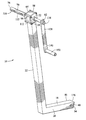
- FIG. 2 is an unassembled side view of the fire hose reel apparatus shown in FIG. 1;
- FIG. 3 is an assembled perspective view of the fire hose reel apparatus shown in FIG. 1, with the fire hose reel apparatus being attached to an automobile hitch, showing the attachment of a fire hose to the hose reel;
- FIG. 4 is an assembled perspective view of the fire hose reel apparatus shown in FIG. 1, with the fire hose reel apparatus being attached to an automobile hitch, showing the fire hose in a rolled up position around the fire hose reel;
- FIG. 5 is an assembled perspective view of the fire hose reel apparatus shown in FIG. 1, with the fire hose reel apparatus being attached to a base support standing on the ground;
- FIG. 6 is a flow diagram illustrating one exemplary method in accordance with the present invention.
- a preferred embodiment of a fire hose apparatus includes a support frame 10 having a lower portion 16 and an upper portion 22 .
- the support frame 10 is preferably steel or another type of metal, but in alternative embodiments, could be manufactured from a hard plastic.
- the support frame 10 is one-piece, and the lower portion 16 and upper portion 22 are welded together.
- the welded one-piece support frame 10 drastically increases the strength, rigidity, and stability of the support frame 10 .
- the lower portion 16 when the support frame 10 is in place, the lower portion 16 preferably extends horizontally, and the upper portion 22 preferably extends generally vertically.
- the cross-section 28 of the support frame 10 is preferably square, but in other embodiments, could consist of other shapes such as rectangular, or cylindrical. The square shape of the support frame 10 , again drastically increases its strength, rigidity, and stability.
- the lower portion 16 defines an aperture 34 extending radially from a first side 40 to a second side 46 of the lower portion 16 .
- the aperture 34 is preferably cylindrical, but may comprise other shapes, such as rectangular, or polygonal.
- the upper portion 22 defines an aperture 52 running radially from a first side 58 to a second side 64 of said upper portion 22 .
- the aperture 52 is preferably cylindrical, but may comprise other shapes, such as rectangular, or polygonal.
- a preferred embodiment also includes a reel shaft 70 having a first end 76 and a second end 82 .
- the reel shaft 70 is preferably cylindrical, comprised of metal, and one-piece. In alternative embodiments, the reel shaft 70 may be manufactured from other hardened materials such as plastic.
- the reel shaft 70 is extended through the aperture 52 in the upper portion 22 of the support frame 10 . When in place, the first end 76 of the reel shaft 70 projects out of the aperture 52 on the second side 64 of the upper portion 22 . Likewise, the second end 82 of the reel shaft 70 projects out of the aperture 52 on the first side 58 of the upper portion 22 .
- the reel shaft 70 is preferably attached to the upper portion 22 of the support frame 10 using one or more bearings.
- ball bearings are utilized, but other bearings, such as roller, ball thrust, roller thrust, and tapered roller thrust may be used.
- a first bearing 88 and a second bearing 94 are utilized.
- the first bearing 88 defines an aperture 100 extending axially through the first bearing 88 .
- the second bearing 94 defines an aperture 104 extending axially through the second bearing 94 .
- the aperture 100 of the first bearing 88 is aligned along the second side 64 of the upper portion 22 of the support frame 10 around the aperture 52 .
- the aperture 104 of the second bearing 94 is aligned along the first side 58 of the support frame 10 around the aperture 52 .
- the bearing structures are preferably metal. As shown, four bolts 108 are utilized to secure the first bearing 88 and second bearing 94 to the upper portion 22 of the support frame 10 . However, a varying number of bolts may be utilized. In a preferred embodiment, the bolts 108 extend from the first bearing 88 through the second bearing 94 outside the periphery 112 of the upper portion 22 of the support frame 10 . In other embodiments, the bolts 108 may extend through the upper portion 22 . Similarly, in other embodiments, the bearing structures may be attached using other types of attachment mechanisms, such as being snap-fit.
- the reel shaft 70 When attached to the support frame 10 , in a preferred embodiment, the reel shaft 70 extends perpendicularly away from the upper portion 22 of the support frame 10 in a horizontal direction parallel to the ground. As best shown in FIGS. 1 and 2, the first end 76 of the reel shaft 70 defines a slot 116 running radially through a cross-section 122 of the reel shaft 70 . The slot 116 extends axially from the first end 76 of the reel shaft 70 towards the second end 82 of the reel shaft 70 .
- a crank 128 is attached to the second end 82 of the reel shaft 70 .
- the crank 128 has a first end 134 and a second end 140 .
- the first end 134 of the crank 128 is attached to the second end 82 of the reel shaft 70 by threading a nut 146 onto the second end 82 of the reel shaft 70 .
- the crank 128 may be connected to the reel shaft 70 through varying means, including snap-fits.
- the second end 140 of the crank 128 contains a handle 152 for turning the crank 128 .
- the crank 128 is metal, but may comprise other hardened materials such as plastic.
- the handle 152 may be a variety of materials, but is preferably plastic or rubber.
- the handle 152 is attached to the crank using a bolt 158 and nut 164 , but may be attached using a variety of means, including snap-fits.
- the lower portion 16 of the support frame 10 may be attached to an automobile hitch 170 by sliding an end 176 of the lower portion 16 into the automobile hitch 170 .
- the automobile hitch 170 is preferably a square pocket to fit the preferably square cross-section 28 of the support frame 10 , but may comprise other shapes such as polygonal.
- a locking pin 182 is extended through an aperture 188 defined in the automobile hitch 170 into the aperture 34 in the lower portion 16 to secure the support frame 10 to the automobile hitch 170 .
- other methods of attachment may be utilized, such as a locking screw, or a snap-fit.
- an end portion 194 of a fire hose 200 is slid into the slot 116 at the first end 76 of the reel shaft 70 to couple the fire hose 200 to the reel shaft 70 .
- An end 204 of the fire hose 200 contains a rim 208 , which is larger in diameter than the diameter of the slot 116 . As such, once the end portion 194 of the fire hose 200 is slid into the slot 116 , the rim 208 prevents the end 204 of the fire hose 200 from slipping through the slot 116 , thereby locking the fire hose 200 in place.
- the reel shaft 70 also rotates thereby winding the fire hose 200 around the reel shaft 70 to wind up the fire hose 200 .
- the crank 128 can then be rotated in an opposite direction to unwind the fire hose 200 .
- the wound up fire hose 200 can be pulled off the reel shaft 70 by sliding the end portion 194 of the fire hose 200 out of the slot 116 at the first end 76 of the reel shaft 70 .
- the lower portion 16 of the support frame 10 may be attached to a base support 212 adapted to stand on the ground.
- the base support 212 comprises a plurality of members 216 welded to form a one-piece base support 212 .
- at least one of the base support members 216 is attached perpendicularly to two or more base support members 216 , one at each end, to increase the stability of the base support 212 .
- the members 216 may be attached using varying methods including bolts and nuts, and snapfits.
- the members 216 are preferably steel or other types of metal, but may be manufactured from other hardened materials including plastic.
- the base support 212 defines a pocket 220 , which preferably jets upwardly at an angle to allow for easy attachment of the support frame 10 .
- An end 176 of the lower portion 16 of the support frame 10 is slid into the pocket 220 of the base support 212 to attach the support frame 10 to the base support 212 .
- one method of winding a fire hose is to first provide a fire hose apparatus 226 .
- the fire hose apparatus comprises a support frame having a lower portion and an upper portion, a reel shaft having first and second ends attached to the upper portion of the support frame, and a crank attached to the second end of the reel shaft.
- the first end of the reel shaft defines a slot running radially through a cross-section of the reel shaft extending axially from the first end of the reel shaft towards the second end of the reel shaft.
- an end portion of a fire hose is slid into the slot at the first end of the reel shaft 232 .
- An end of the fire hose may have a rim larger in diameter than the slot in order to prevent the end of the fire hose from slipping out of the slot.
- the crank is rotated to wind the fire hose around the reel shaft 236 .
- a further step may comprise attaching an end of the lower portion of the support frame to an automobile hitch 242 .
- This step may be accomplished by sliding an end of the lower portion of the support frame into an automobile hitch pocket, and extending a locking pin through apertures defined in the lower portion of the support frame and the automobile hitch pocket.
- Another step may comprise sliding an end of the lower portion of the support frame into the pocket of a base support to attach the support frame to the base support 248 .
- Yet another step may comprise pulling the wound hose off the reel shaft 254 . This may be accomplished by sliding the end portion of the fire hose out of the slot at the first end of the reel shaft.
- a final step may comprise rotating the crank in an opposite direction to unwind the fire hose from the reel shaft 260 .
Landscapes
- Storing, Repeated Paying-Out, And Re-Storing Of Elongated Articles (AREA)
Abstract
A portable fire hose reel apparatus, and a method for its use, is provided. In one embodiment, the apparatus comprises a support frame having a lower portion and an upper portion, a reel shaft having first and second ends, and a crank attached to the second end of the reel shaft. The reel shaft is attached to the upper portion of the support frame. The first end of the reel shaft defines a slot running radially through a cross-section of the reel shaft, which extends axially from the first end of the reel shaft towards the second end of the reel shaft. In another embodiment, the reel shaft extends through an aperture running radially through a cross section of the upper portion from a first to second side. The first end of the reel shaft projects out of the aperture on the first side of the upper portion, while the second end of the reel shaft projects out of the aperture on the second side of the upper portion. To couple a fire hose to the reel shaft, the slot is adapted to allow an end portion of a fire hose to be slid into the slot at the first end of the reel shaft. The crank is then rotated to wind the fire hose around the reel shaft. In other embodiments, the fire hose apparatus is adapted to be attached to an automobile hitch, or to a base support stationed on the ground.
Description
- The present invention relates generally to a portable hose reel apparatus for rolling fire hoses, and to a method for use thereof.
- Fire hoses are heavy by nature and can be difficult to roll up, particularly when water remnants remain in the fire hose. Since the fire hoses are heavy, they require a hose reel device to roll them up so that they can be stored. Some existing fire hose reel devices are portable, and allow for relatively easy rolling of the fire hose. One such existing device described in U.S. Pat. No. 6,206,317 B1, comprises a main support, a hose reel having an axle, a crank, and a separate retainer. In order to roll a fire hose using that device, the retainer has to be pulled out from the hose reel. An end of the hose is then positioned between the rods of the retainer, and the retainer is reattached to the hose reel. The crank is then rotated, and the hose winds around the retainer. A hose rim attached to the hose reel keeps the hose in place as it is winded around the retainer.
- However, the available fire hose reel devices utilize an excess of components, thereby unduly increasing the cost of manufacturing the devices, increasing the time required to couple fire hoses to the devices, and increasing the complexity of their operation.
- As a result, a simple, efficient, portable fire hose reel apparatus, and a method for its use, is required having a minimum number of components in order to cut manufacturing cost, and to make operation of the apparatus more user friendly.
- It is in general an object of the invention to provide a simple, efficient, portable hose reel apparatus, and method for use thereof, for rolling fire hoses.
- In one aspect, this invention provides a fire hose apparatus comprising a support frame having a lower portion and an upper portion, a reel shaft having first and second ends, and a crank attached to the second end of the reel shaft. The reel shaft is attached to the upper portion of the support frame. The first end of the reel shaft defines a slot running radially through a cross-section of the reel shaft, which extends axially from the first end of the reel shaft towards the second end of the reel shaft.
- In another aspect, this invention again provides a fire hose apparatus comprising a support frame having a lower portion and an upper portion, a reel shaft having first and second ends, and a crank attached to the second end of the reel shaft. The upper portion defines an aperture running radially through a cross section of the upper portion from a first to second side of the upper portion. The reel shaft extends through the aperture in the upper portion of the support frame, with the first end of the reel shaft projecting out of the aperture on the first side of the upper portion, and the second end of the reel shaft projecting out of the aperture on the second side of the upper portion. The first end of the reel shaft defines a slot running radially through a cross-section of the reel shaft, the slot extending axially along at least a portion of the reel shaft.
- In a final aspect, this invention provides a method of winding a fire hose. The method comprises providing a fire hose apparatus, sliding an end portion of a fire hose into a slot at the first end of a reel shaft, and rotating a crank thereby winding the fire hose around the reel shaft. The fire hose apparatus comprises a support frame having a lower portion and an upper portion, a reel shaft having first and second ends, and a crank attached to the second end of the reel shaft. The reel shaft is attached to the upper portion of the support frame. The first end of the reel shaft defines a slot running radially through a cross-section of the reel shaft, the slot extending axially from the first end of the reel shaft towards the second end of the reel shaft.
- The present invention, together with further objects and advantages, will be best understood by reference to the following detailed description taken in conjunction with the accompanying drawings.
- FIG. 1 is an assembled perspective view of one embodiment of a fire hose reel apparatus;
- FIG. 2 is an unassembled side view of the fire hose reel apparatus shown in FIG. 1;
- FIG. 3 is an assembled perspective view of the fire hose reel apparatus shown in FIG. 1, with the fire hose reel apparatus being attached to an automobile hitch, showing the attachment of a fire hose to the hose reel;
- FIG. 4 is an assembled perspective view of the fire hose reel apparatus shown in FIG. 1, with the fire hose reel apparatus being attached to an automobile hitch, showing the fire hose in a rolled up position around the fire hose reel;
- FIG. 5 is an assembled perspective view of the fire hose reel apparatus shown in FIG. 1, with the fire hose reel apparatus being attached to a base support standing on the ground; and
- FIG. 6 is a flow diagram illustrating one exemplary method in accordance with the present invention.
- Referring to the drawings, and as best shown in FIGS. 1 and 2, a preferred embodiment of a fire hose apparatus includes a
support frame 10 having alower portion 16 and anupper portion 22. Thesupport frame 10 is preferably steel or another type of metal, but in alternative embodiments, could be manufactured from a hard plastic. In a preferred embodiment, thesupport frame 10 is one-piece, and thelower portion 16 andupper portion 22 are welded together. The welded one-piece support frame 10 drastically increases the strength, rigidity, and stability of thesupport frame 10. As shown in FIGS. 3 and 4, when thesupport frame 10 is in place, thelower portion 16 preferably extends horizontally, and theupper portion 22 preferably extends generally vertically. Thecross-section 28 of thesupport frame 10 is preferably square, but in other embodiments, could consist of other shapes such as rectangular, or cylindrical. The square shape of thesupport frame 10, again drastically increases its strength, rigidity, and stability. - As shown in FIG. 2, the
lower portion 16 defines anaperture 34 extending radially from afirst side 40 to asecond side 46 of thelower portion 16. Theaperture 34 is preferably cylindrical, but may comprise other shapes, such as rectangular, or polygonal. Similarly, theupper portion 22 defines anaperture 52 running radially from afirst side 58 to asecond side 64 of saidupper portion 22. Again, theaperture 52 is preferably cylindrical, but may comprise other shapes, such as rectangular, or polygonal. - As best shown in FIGS. 1 and 2, a preferred embodiment also includes a
reel shaft 70 having afirst end 76 and asecond end 82. Thereel shaft 70 is preferably cylindrical, comprised of metal, and one-piece. In alternative embodiments, thereel shaft 70 may be manufactured from other hardened materials such as plastic. Thereel shaft 70 is extended through theaperture 52 in theupper portion 22 of thesupport frame 10. When in place, thefirst end 76 of thereel shaft 70 projects out of theaperture 52 on thesecond side 64 of theupper portion 22. Likewise, thesecond end 82 of thereel shaft 70 projects out of theaperture 52 on thefirst side 58 of theupper portion 22. - The
reel shaft 70 is preferably attached to theupper portion 22 of thesupport frame 10 using one or more bearings. Preferably, ball bearings are utilized, but other bearings, such as roller, ball thrust, roller thrust, and tapered roller thrust may be used. In one embodiment, a first bearing 88 and a second bearing 94 are utilized. The first bearing 88 defines anaperture 100 extending axially through the first bearing 88. Similarly, the second bearing 94 defines anaperture 104 extending axially through the second bearing 94. Theaperture 100 of the first bearing 88 is aligned along thesecond side 64 of theupper portion 22 of thesupport frame 10 around theaperture 52. Likewise, theaperture 104 of the second bearing 94 is aligned along thefirst side 58 of thesupport frame 10 around theaperture 52. The bearing structures are preferably metal. As shown, fourbolts 108 are utilized to secure the first bearing 88 and second bearing 94 to theupper portion 22 of thesupport frame 10. However, a varying number of bolts may be utilized. In a preferred embodiment, thebolts 108 extend from the first bearing 88 through the second bearing 94 outside theperiphery 112 of theupper portion 22 of thesupport frame 10. In other embodiments, thebolts 108 may extend through theupper portion 22. Similarly, in other embodiments, the bearing structures may be attached using other types of attachment mechanisms, such as being snap-fit. - When attached to the
support frame 10, in a preferred embodiment, thereel shaft 70 extends perpendicularly away from theupper portion 22 of thesupport frame 10 in a horizontal direction parallel to the ground. As best shown in FIGS. 1 and 2, thefirst end 76 of thereel shaft 70 defines aslot 116 running radially through across-section 122 of thereel shaft 70. Theslot 116 extends axially from thefirst end 76 of thereel shaft 70 towards thesecond end 82 of thereel shaft 70. - A
crank 128 is attached to thesecond end 82 of thereel shaft 70. Thecrank 128 has afirst end 134 and asecond end 140. Thefirst end 134 of thecrank 128 is attached to thesecond end 82 of thereel shaft 70 by threading anut 146 onto thesecond end 82 of thereel shaft 70. In other embodiments, thecrank 128 may be connected to thereel shaft 70 through varying means, including snap-fits. Thesecond end 140 of thecrank 128 contains ahandle 152 for turning thecrank 128. Preferably, thecrank 128 is metal, but may comprise other hardened materials such as plastic. Likewise, thehandle 152 may be a variety of materials, but is preferably plastic or rubber. Preferably, thehandle 152 is attached to the crank using abolt 158 andnut 164, but may be attached using a variety of means, including snap-fits. - As shown in FIGS. 3 and 4, the
lower portion 16 of thesupport frame 10 may be attached to anautomobile hitch 170 by sliding anend 176 of thelower portion 16 into theautomobile hitch 170. Theautomobile hitch 170 is preferably a square pocket to fit the preferablysquare cross-section 28 of thesupport frame 10, but may comprise other shapes such as polygonal. After thelower portion 16 is slid into theautomobile hitch 170, alocking pin 182 is extended through anaperture 188 defined in theautomobile hitch 170 into theaperture 34 in thelower portion 16 to secure thesupport frame 10 to theautomobile hitch 170. In alternative embodiments, other methods of attachment may be utilized, such as a locking screw, or a snap-fit. - In operation, an
end portion 194 of afire hose 200 is slid into theslot 116 at thefirst end 76 of thereel shaft 70 to couple thefire hose 200 to thereel shaft 70. Anend 204 of thefire hose 200 contains arim 208, which is larger in diameter than the diameter of theslot 116. As such, once theend portion 194 of thefire hose 200 is slid into theslot 116, therim 208 prevents theend 204 of thefire hose 200 from slipping through theslot 116, thereby locking thefire hose 200 in place. At this point, when thecrank 128 is rotated, thereel shaft 70 also rotates thereby winding thefire hose 200 around thereel shaft 70 to wind up thefire hose 200. The crank 128 can then be rotated in an opposite direction to unwind thefire hose 200. Additionally, the wound upfire hose 200 can be pulled off thereel shaft 70 by sliding theend portion 194 of thefire hose 200 out of theslot 116 at thefirst end 76 of thereel shaft 70. - As shown in FIG. 5, the
lower portion 16 of thesupport frame 10 may be attached to abase support 212 adapted to stand on the ground. Thebase support 212 comprises a plurality ofmembers 216 welded to form a one-piece base support 212. Preferably, at least one of thebase support members 216 is attached perpendicularly to two or morebase support members 216, one at each end, to increase the stability of thebase support 212. In other embodiments, themembers 216 may be attached using varying methods including bolts and nuts, and snapfits. Themembers 216 are preferably steel or other types of metal, but may be manufactured from other hardened materials including plastic. Thebase support 212 defines apocket 220, which preferably jets upwardly at an angle to allow for easy attachment of thesupport frame 10. Anend 176 of thelower portion 16 of thesupport frame 10 is slid into thepocket 220 of thebase support 212 to attach thesupport frame 10 to thebase support 212. - As shown in FIG. 6, one method of winding a fire hose is to first provide a
fire hose apparatus 226. The fire hose apparatus comprises a support frame having a lower portion and an upper portion, a reel shaft having first and second ends attached to the upper portion of the support frame, and a crank attached to the second end of the reel shaft. The first end of the reel shaft defines a slot running radially through a cross-section of the reel shaft extending axially from the first end of the reel shaft towards the second end of the reel shaft. Next, an end portion of a fire hose is slid into the slot at the first end of thereel shaft 232. An end of the fire hose may have a rim larger in diameter than the slot in order to prevent the end of the fire hose from slipping out of the slot. Finally, the crank is rotated to wind the fire hose around thereel shaft 236. - A further step may comprise attaching an end of the lower portion of the support frame to an
automobile hitch 242. This step may be accomplished by sliding an end of the lower portion of the support frame into an automobile hitch pocket, and extending a locking pin through apertures defined in the lower portion of the support frame and the automobile hitch pocket. Another step may comprise sliding an end of the lower portion of the support frame into the pocket of a base support to attach the support frame to thebase support 248. Yet another step may comprise pulling the wound hose off thereel shaft 254. This may be accomplished by sliding the end portion of the fire hose out of the slot at the first end of the reel shaft. A final step may comprise rotating the crank in an opposite direction to unwind the fire hose from the reel shaft 260. - It is to be understood that the invention is not to be limited to the exact construction and/or method which has been illustrated and discussed above, but that various changes and/or modifications may be made without departing from the spirit and the scope of the invention.
Claims (32)
1. A fire hose apparatus comprising:
a support frame having a lower portion and an upper portion;
a reel shaft having first and second ends, wherein said reel shaft is attached to the upper portion of said support frame, the first end of said reel shaft defines a slot running radially through a cross-section of said reel shaft, said slot extending axially from the first end of said reel shaft towards the second end of said reel shaft; and
a crank attached to said second end of said reel shaft.
2. The invention of claim 1 wherein said support frame is one-piece.
3. The invention of claim 1 wherein said support frame is metal.
4. The invention of claim 1 wherein said lower portion extends generally horizontally, and said upper portion extends generally vertically.
5. The invention of claim 1 wherein a cross section of said support frame is rectangular.
6. The invention of claim 1 wherein said lower portion is welded to said upper portion.
7. The invention of claim 1 wherein said lower portion is adapted to be attached to an automobile hitch.
8. The invention of claim 7 wherein said lower portion defines an aperture extending from a first side of said lower portion to a second side of said lower portion, a cross section of said lower portion is rectangular, an end of said lower portion is adapted to be slid into a rectangular automobile hitch, and a locking pin is provided to extend into said aperture in said lower portion to lock said support frame to the automobile hitch.
9. The invention of claim 1 further comprising a base support adapted to stand on the ground, wherein the base support defines a pocket, wherein an end of said lower portion of said support frame is adapted to be slid into the pocket to attach said support frame to said base support.
10. The invention of claim 9 wherein said base support comprises a plurality of members welded to form a one-piece base support.
11. The invention of claim 1 wherein said reel shaft is cylindrical.
12. The invention of claim 1 wherein said reel shaft is metal.
13. The invention of claim 12 wherein said reel shaft extends perpendicularly away from said upper portion of said support frame in a horizontal direction.
14. The invention of claim 1 wherein said upper portion of said support frame defines an aperture running radially through a cross section of said upper portion from a first to second side of said upper portion.
15. The invention of claim 14 wherein said reel shaft extends through said aperture in said upper portion of said support frame, said first end of said reel shaft projects out of said aperture on said first side of said upper portion, and said second end of said reel shaft projects out of said aperture on said second side of said upper portion.
16. The invention of claim 1 wherein said reel shaft is attached to the upper portion of said support frame using at least one bearing.
17. The invention of claim 16 wherein said reel shaft is attached to the upper portion of said support frame using first and second bearings, wherein said first bearing is aligned along a first side of said upper portion, said second bearing is aligned along a second side of said upper portion, and said first and second bearings are attached to said upper portion of said support frame using one or more bolts.
18. The invention of claim 1 wherein said slot is adapted to allow an end portion of a fire hose to be slid into said slot at the first end of said reel shaft to couple the fire hose to said reel shaft.
19. The invention of claim 18 wherein an end of the fire hose has a rim larger in diameter than said slot, said rim preventing the end of said fire hose from slipping through said slot.
20. The invention of claim 19 wherein said fire hose winds around said reel shaft as said crank is rotated.
21. The invention of claim 1 wherein said crank has a first end and a second end, said first end of said crank is attached to said second end of said reel shaft, and said second end of said crank contains a handle for turning the crank.
22. The invention of claim 1 wherein said crank is metal, and said crank contains a plastic handle.
23. A fire hose apparatus comprising:
a support frame having a lower portion and an upper portion, wherein said upper portion defines an aperture running radially through a cross section of said upper portion from a first to second side of said upper portion;
a reel shaft having first and second ends, wherein said reel shaft extends through said aperture in said upper portion of said support frame, said first end of said reel shaft projects out of said aperture on said first side of said upper portion, said second end of said reel shaft projects out of said aperture on said second side of said upper portion, said first end of said reel shaft defines a slot running radially through a cross-section of said reel shaft, said slot extends axially along at least a portion of said reel shaft; and
a crank attached to said second end of said reel shaft.
24. The invention of claim 23 wherein said slot extends axially from the first end of said reel shaft towards the second end of said reel shaft, said slot being adapted to allow an end portion of a fire hose to be slid into said slot at the first end of said reel shaft to couple the fire hose to said reel shaft.
25. A method of winding a fire hose comprising:
providing a fire hose apparatus comprising a support frame having a lower portion and an upper portion, a reel shaft having first and second ends, wherein said reel shaft is attached to the upper portion of said support frame, the first end of said reel shaft defines a slot running radially through a cross-section of said reel shaft, said slot extending axially from the first end of said reel shaft towards the second end of said reel shaft, and a crank attached to said second end of said reel shaft;
sliding an end portion of a fire hose into said slot at the first end of said reel shaft; and
rotating said crank thereby winding said fire hose around said reel shaft.
26. The invention of claim 25 wherein an end of the fire hose has a rim larger in diameter than said slot, said rim preventing the end of said fire hose from slipping through said slot after said end portion of said fire hose is slid into said slot at the first end of said reel shaft.
27. The invention of claim 25 further comprising the step of attaching an end of said lower portion of said support frame to an automobile hitch.
28. The invention of claim 27 wherein said lower portion defines an aperture extending from a first side of said lower portion to a second side of said lower portion, a cross section of said lower portion is rectangular, and the step of attaching an end of said lower portion of said support frame to an automobile hitch comprises sliding an end of said lower portion into a rectangular automobile hitch, and extending a locking pin into said aperture in said lower portion to lock said support frame to said automobile hitch.
29. The invention of claim 25 further comprising a base support adapted to stand on the ground, wherein said base support defines a pocket, and further comprising the step of sliding an end of said lower portion of said support frame into said pocket to attach said support frame to said base support.
30. The invention of claim 29 wherein said base support comprises a plurality of members welded to form a one-piece base support.
31. The invention of claim 25 further comprising the step of pulling the wound hose off said reel shaft.
32. The invention of claim 25 further comprising the step of rotating said crank in an opposite direction to unwind said fire hose from said reel shaft.
Priority Applications (1)
| Application Number | Priority Date | Filing Date | Title |
|---|---|---|---|
| US10/123,934 US20030192979A1 (en) | 2002-04-16 | 2002-04-16 | Hose reel apparatus and method |
Applications Claiming Priority (1)
| Application Number | Priority Date | Filing Date | Title |
|---|---|---|---|
| US10/123,934 US20030192979A1 (en) | 2002-04-16 | 2002-04-16 | Hose reel apparatus and method |
Publications (1)
| Publication Number | Publication Date |
|---|---|
| US20030192979A1 true US20030192979A1 (en) | 2003-10-16 |
Family
ID=28790844
Family Applications (1)
| Application Number | Title | Priority Date | Filing Date |
|---|---|---|---|
| US10/123,934 Abandoned US20030192979A1 (en) | 2002-04-16 | 2002-04-16 | Hose reel apparatus and method |
Country Status (1)
| Country | Link |
|---|---|
| US (1) | US20030192979A1 (en) |
Cited By (8)
| Publication number | Priority date | Publication date | Assignee | Title |
|---|---|---|---|---|
| US20070075177A1 (en) * | 2005-10-03 | 2007-04-05 | Donald Mehrer | Strap roll up device |
| US20100090053A1 (en) * | 2008-10-09 | 2010-04-15 | Rodney Stiltner | Hitch Wire Stand |
| US7793881B1 (en) | 2008-01-02 | 2010-09-14 | Jose Hipolito Torres | Portable multiple hose roller |
| ITPV20090008A1 (en) * | 2009-05-07 | 2010-11-08 | Rino Greguoldo | WRAPPER DEVICE |
| US10414624B1 (en) * | 2014-09-23 | 2019-09-17 | Kevin D. Berry | Motorized flat web winder |
| US20230071990A1 (en) * | 2020-02-13 | 2023-03-09 | Kevin RENOUF | Winder |
| US11633638B2 (en) | 2021-04-20 | 2023-04-25 | Daniel James Corrigan | Fire hose reeling system |
| US20240174478A1 (en) * | 2022-11-29 | 2024-05-30 | William Stolz | Blanket Rolling Device |
-
2002
- 2002-04-16 US US10/123,934 patent/US20030192979A1/en not_active Abandoned
Cited By (8)
| Publication number | Priority date | Publication date | Assignee | Title |
|---|---|---|---|---|
| US20070075177A1 (en) * | 2005-10-03 | 2007-04-05 | Donald Mehrer | Strap roll up device |
| US7793881B1 (en) | 2008-01-02 | 2010-09-14 | Jose Hipolito Torres | Portable multiple hose roller |
| US20100090053A1 (en) * | 2008-10-09 | 2010-04-15 | Rodney Stiltner | Hitch Wire Stand |
| ITPV20090008A1 (en) * | 2009-05-07 | 2010-11-08 | Rino Greguoldo | WRAPPER DEVICE |
| US10414624B1 (en) * | 2014-09-23 | 2019-09-17 | Kevin D. Berry | Motorized flat web winder |
| US20230071990A1 (en) * | 2020-02-13 | 2023-03-09 | Kevin RENOUF | Winder |
| US11633638B2 (en) | 2021-04-20 | 2023-04-25 | Daniel James Corrigan | Fire hose reeling system |
| US20240174478A1 (en) * | 2022-11-29 | 2024-05-30 | William Stolz | Blanket Rolling Device |
Similar Documents
| Publication | Publication Date | Title |
|---|---|---|
| US4324370A (en) | Pool cover roller assembly | |
| US5088681A (en) | Anchor device | |
| US20030192979A1 (en) | Hose reel apparatus and method | |
| US5437424A (en) | Septic pipe field drain holders | |
| US20060097117A1 (en) | Portable umbrella stand | |
| US20150122929A1 (en) | Cable reel assembly | |
| US5809930A (en) | Flagpole rotation device | |
| DE2322081A1 (en) | STAND OR POLES FOR CARRYING LIGHTING BODIES | |
| CN2467678Y (en) | Ground anchor | |
| US6719241B2 (en) | Cable tie-off device for cable lifts | |
| US20070181171A1 (en) | Tie down stake, angle | |
| KR101756192B1 (en) | Tension maintenance placard | |
| US20140091170A1 (en) | Device for repairing wire spools | |
| DE29503115U1 (en) | Ground anchors or screw pegs for fastening tension lines, tent loops, poles and tubular elements to the ground | |
| US7530520B2 (en) | Apparatus and method for winding wire | |
| US3106358A (en) | Fence winding apparatus | |
| CN211505594U (en) | Anemoscope for meteorological monitoring | |
| JP3764601B2 (en) | Installation structure of crossbar in pseudo-tree fence | |
| US20050188636A1 (en) | Coupling nut for high wind applications | |
| US20180290856A1 (en) | Pipe Unroller | |
| US20060237575A1 (en) | Portable volleyball net and supports | |
| US20230331514A1 (en) | Drill-Powered Drip Tape Winder and Method of Use | |
| CN218242224U (en) | GPS-RTK base station radio station antenna prevents empting fixing device | |
| US2963239A (en) | Wire handling attachment for tractors | |
| CN212149764U (en) | Sleeve memory |
Legal Events
| Date | Code | Title | Description |
|---|---|---|---|
| STCB | Information on status: application discontinuation |
Free format text: ABANDONED -- FAILURE TO RESPOND TO AN OFFICE ACTION |