US20030192848A1 - Display rack - Google Patents
Display rack Download PDFInfo
- Publication number
- US20030192848A1 US20030192848A1 US10/427,853 US42785303A US2003192848A1 US 20030192848 A1 US20030192848 A1 US 20030192848A1 US 42785303 A US42785303 A US 42785303A US 2003192848 A1 US2003192848 A1 US 2003192848A1
- Authority
- US
- United States
- Prior art keywords
- crosspiece
- upright
- shelf
- snap
- clips
- Prior art date
- Legal status (The legal status is an assumption and is not a legal conclusion. Google has not performed a legal analysis and makes no representation as to the accuracy of the status listed.)
- Granted
Links
- 239000000463 material Substances 0.000 claims description 3
- 238000009434 installation Methods 0.000 description 2
- 229910001209 Low-carbon steel Inorganic materials 0.000 description 1
- 229910000639 Spring steel Inorganic materials 0.000 description 1
- 230000013011 mating Effects 0.000 description 1
- 239000002184 metal Substances 0.000 description 1
- 230000004048 modification Effects 0.000 description 1
- 238000012986 modification Methods 0.000 description 1
- 239000007787 solid Substances 0.000 description 1
- 210000003813 thumb Anatomy 0.000 description 1
Images


Classifications
-
- A—HUMAN NECESSITIES
- A47—FURNITURE; DOMESTIC ARTICLES OR APPLIANCES; COFFEE MILLS; SPICE MILLS; SUCTION CLEANERS IN GENERAL
- A47F—SPECIAL FURNITURE, FITTINGS, OR ACCESSORIES FOR SHOPS, STOREHOUSES, BARS, RESTAURANTS OR THE LIKE; PAYING COUNTERS
- A47F5/00—Show stands, hangers, or shelves characterised by their constructional features
- A47F5/01—Show stands, hangers, or shelves characterised by their constructional features made of tubes or wire
-
- A—HUMAN NECESSITIES
- A47—FURNITURE; DOMESTIC ARTICLES OR APPLIANCES; COFFEE MILLS; SPICE MILLS; SUCTION CLEANERS IN GENERAL
- A47F—SPECIAL FURNITURE, FITTINGS, OR ACCESSORIES FOR SHOPS, STOREHOUSES, BARS, RESTAURANTS OR THE LIKE; PAYING COUNTERS
- A47F5/00—Show stands, hangers, or shelves characterised by their constructional features
- A47F5/04—Stands with a central pillar, e.g. tree type
- A47F5/06—Stands with a central pillar, e.g. tree type adjustable
Definitions
- the present invention relates to display racks, and in particular to display racks that can be assembled in multiple configurations in a simple and reliable manner.
- Carrigan U.S. Pat. No. 5,272,991 discloses a display rack in which wire shelves are mounted in place on horizontally extending bars.
- each of the bars defines a constant cross section
- each of the shelves includes a C-channel shaped to receive one of the bars.
- the shelves are assembled onto respective bars by telescopically sliding them into position from one end of the bar.
- the shelves can be positioned in any of various positions with respect to the bar.
- the preferred embodiment described below includes at least one shelf that has first and second clips.
- Each clip has an upper lip element configured to fit over and engage an upper side of a crosspiece, and a spring element configured to snap-lock against a lower, opposed side of the crosspiece.
- the shelf can be mounted on the crosspiece in any one of three positions: a first position, in which the two clips are disposed on opposite sides of an upright that supports the crosspiece; a second position, in which both of the clips are disposed on a first side of the upright; and a third position, in which both of the clips are disposed on a second side of the upright.
- This display rack provides a simple and effective arrangement for adjustably mounting the shelf in any one of the three desired positions on the crosspiece.
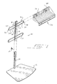
- FIG. 1 is an exploded perspective view of a display rack that incorporates a preferred embodiment of this invention.
- FIG. 2 is an exploded perspective view of one of two clips mounted to the back of the shelf of FIG. 1.
- FIG. 3 is a fragmentary rear perspective view of the shelf of FIG. 1.
- FIG. 4 is a fragmentary top plan view of the shelf of FIG. 1.
- FIGS. 5 and 6 are fragmentary side sectional views of the shelf of FIG. 1 during installation (FIG. 5) and after installation has been completed (FIG. 6) on the crosspiece of FIG. 1.
- FIGS. 7, 8 and 9 are schematic rear elevational views showing the shelf of FIG. 1 mounted to the crosspiece of FIG. 1 in first, second and third positions, respectively.
- FIG. 1 shows an exploded perspective view of a display rack 10 .
- the view of FIG. 1 shows only a single shelf 34 , though in actual practice more than one shelf 34 is typically used.
- the display rack 10 includes a base 12 that supports a vertically extending post 14 .
- the base 12 can be formed as a metal plate
- the post 14 can be formed as a rigid C-channel that is welded in place to the base 12 .
- An upright 16 is releasably secured to the post 14 .
- the upright 16 can be formed as a box channel that telescopically receives the post 14 .
- a threaded fastener such as a thumb screw 15 can be threaded to the upright 16 to secure the upright 16 releasably in place on the post 14 . This arrangement allows the user to adjust the height of the upright 16 relative to the base 12 .
- the upright 16 supports one or more crosspieces 17 .
- each of the crosspieces 17 includes a respective wire loop having first and second parts 18 , 20 on respective sides of the upright 16 .
- the crosspiece 17 defines an upper side 22 and a lower side 24 , and each of the parts 18 , 20 includes a respective end portion 26 , 28 .
- the wire loop of the first part 18 bounds a space 30
- the wire loop of the second part 20 bounds a space 32 .
- the display rack 10 also includes one or more shelves 34 , and each of the shelves 34 includes first and second clips 36 , 38 disposed in side-by-side relationship on a rear portion of the shelf 34 .
- FIG. 2 provides an exploded perspective view of one of the clips 36 , 38 .
- each clip includes an upper lip element 40 and a lower spring element 42 .
- the lip element 40 is formed as part of a C-channel, and the spring element 42 is secured to the C-channel, as for example with a rivet 43 .
- Tabs 44 , 46 are bent out of the plane of the clips 36 , 38 , such that the tabs 44 , 46 extend away from the shelf 34 of FIG. 1.
- FIGS. 3 and 4 provide rear and top views, respectively, showing the relationship between the various elements of the clips 36 , 38 and the shelf 34 .
- FIGS. 5 and 6 show two steps in installing or removing the shelf 34 from the crosspiece 17 , as viewed from the side.
- the lip element 40 is first placed over the upper side 22 of the crosspiece 17 , with the shelf 34 angled upwardly. In this position the spring element 42 is disposed forwardly of the lower side 24 of the crosspiece 17 .
- the shelf 34 is rotated about the lip element 40 from the position of FIG. 5 to that of FIG. 6. In this position, the spring element 42 fits around and snap-locks against the lower side 24 of the crosspiece 17 .
- the tabs 44 , 46 fit into one of the spaces 30 , 32 bounded by the crosspiece 17 .
- the spring element 42 is moved downwardly from the position shown in FIG. 6, thereby releasing the shelf 34 for rotation about the lip element 40 to the position of FIG. 5, where it can be lifted and removed from the crosspiece 17 .
- FIGS. 7, 8 and 9 show three alternative positions in which the shelf 34 can be mounted on the crosspiece 17 .
- FIGS. 7 - 9 show the display rack 10 from the rear, and side-specific reference numerals are therefore reversed in FIGS. 7 - 9 as compared with FIG. 1.
- the shelf 34 is positioned with the clips 36 , 38 on respective sides 48 , 50 of the upright 16 .
- the first and second clips 36 , 38 are secured to the first and second parts 18 , 20 of the crosspiece 17 , respectively.
- Tab 44 of the clip 38 is positioned to mechanically interfere with the end 28 , thereby preventing any sliding movement of the shelf 34 to the left as shown in FIG. 7.
- the tab 46 of the first clip 36 is positioned to mechanically interfere with the first end 26 , thereby preventing any substantial sliding movement of the shelf 34 to the right, as shown in FIG. 7.
- FIG. 8 shows the shelf 34 mounted in a second position 70 on the crosspiece 17 .
- the second clip 38 is snap-latched in place on the first part 18 of the crosspiece 17 .
- Tab 46 of the second clip 38 mechanically interferes with the first end portion 26 , thereby preventing any substantial sliding movement of the shelf 34 to the right, as shown in FIG. 8.
- the tab 44 of the second clip 38 or another structural part of the second clip 38 mechanically interferes with the upright 16 to prevent any substantial sliding movement of the shelf 34 to the left in the view of FIG. 8. Note that in this example, the first clip 36 is not engaged with the crosspiece 17 , and the right-hand portion of the shelf 34 is cantilevered beyond the crosspiece 17 in the view of FIG. 8.
- FIG. 9 shows the shelf 34 mounted in a third position 80 , in which the first clip 36 is snap-locked to the second part 20 of the crosspiece 17 .
- the second clip 38 is not engaged with the crosspiece 17 , and the left-hand portion of the shelf 34 is cantilevered beyond the crosspiece 17 in the view of FIG. 9.
- the tab 44 of the first clip 36 mechanically interferes with the second end portion 28 , thereby preventing any substantial sliding movement of the shelf 34 to the left in the view of FIG. 9.
- the tab 46 or some other portion of the first clip 36 mechanically interferes with the upright 16 to prevent any substantial sliding movement of the shelf 34 to the right in the view of FIG. 9.
- the display rack 10 can easily be assembled and disassembled with the shelf 34 in any one of the first, second, and third positions 60 , 70 , 80 .
- the tabs 44 , 46 or other parts of the clips 36 , 38 prevent any substantial undesired sliding movement of the shelf 34 along the crosspiece 17 in all three positions.
- a simple rotational movement is all that is required to latch shelf 34 in position on the crosspiece 17 and to remove the shelf 34 from the crosspiece 17 , and all cumbersome telescoping sliding movements are eliminated.
- the upright 16 can take any desired structural form, and can be formed as a plate, a rod, a C-channel, or another shape in an alternative embodiment.
- the base 12 can be formed as a plate or a wire frame, or alternatively the base can include a socket or a post intended to receive a mating structure.
- the crosspiece 17 can be formed in one or more parts using any suitable structural element.
- the crosspiece can be formed as a plate or a channel.
- the clips 36 , 38 may be formed from multiple parts that are separately mounted to the shelf.
- the lip elements 40 , spring elements 42 , and tabs 44 , 46 can all be separately mounted to the shelf 34 , without intermediate structures such as that provided by the illustrated channel.
- the clips 36 , 38 may correspond to laterally-spaced portions of a single structural element such as a plate or a channel.
- the shelf 34 can be a wire shelf as illustrated, or it can include solid or apertured plates. The shelf may or may not have raised walls and a raised back.
Landscapes
- Display Racks (AREA)
Abstract
A display rack includes an upright that supports a crosspiece and one or more shelves. Each shelf includes two clips, and each clip includes a lip element configured to fit over and to engage an upper surface of the crosspiece, and a spring element configured to snap-lock against a lower, opposed of the crosspiece. The first and second clips are positioned on the shelf such as the shelf is mountable on the crosspiece in three different positions: a first position, in which each clip is disposed on a respective side of the upright; a second position, in which both clips are disposed on a first side of the upright; and a third position, in which both clips are disposed on the other side of the upright.
Description
- The present invention relates to display racks, and in particular to display racks that can be assembled in multiple configurations in a simple and reliable manner.
- Carrigan U.S. Pat. No. 5,272,991 discloses a display rack in which wire shelves are mounted in place on horizontally extending bars. In the disclosed display rack, each of the bars defines a constant cross section, and each of the shelves includes a C-channel shaped to receive one of the bars. The shelves are assembled onto respective bars by telescopically sliding them into position from one end of the bar. As shown on the front page of the Carrigan patent, the shelves can be positioned in any of various positions with respect to the bar.
- The sliding action used to install the shelves on the bar in the Carrigan patent requires a shelf to be moved horizontally beyond the end of the bar in order to remove the shelf from the bar. This may not be convenient in all applications.
- By way of general introduction, the preferred embodiment described below includes at least one shelf that has first and second clips. Each clip has an upper lip element configured to fit over and engage an upper side of a crosspiece, and a spring element configured to snap-lock against a lower, opposed side of the crosspiece. The shelf can be mounted on the crosspiece in any one of three positions: a first position, in which the two clips are disposed on opposite sides of an upright that supports the crosspiece; a second position, in which both of the clips are disposed on a first side of the upright; and a third position, in which both of the clips are disposed on a second side of the upright.
- This display rack provides a simple and effective arrangement for adjustably mounting the shelf in any one of the three desired positions on the crosspiece.
- This section has been provided by way of general introduction, and it should not be used to narrow the scope of the following claims.
- FIG. 1 is an exploded perspective view of a display rack that incorporates a preferred embodiment of this invention.
- FIG. 2 is an exploded perspective view of one of two clips mounted to the back of the shelf of FIG. 1.
- FIG. 3 is a fragmentary rear perspective view of the shelf of FIG. 1.
- FIG. 4 is a fragmentary top plan view of the shelf of FIG. 1.
- FIGS. 5 and 6 are fragmentary side sectional views of the shelf of FIG. 1 during installation (FIG. 5) and after installation has been completed (FIG. 6) on the crosspiece of FIG. 1.
- FIGS. 7, 8 and 9 are schematic rear elevational views showing the shelf of FIG. 1 mounted to the crosspiece of FIG. 1 in first, second and third positions, respectively.
- Turning now to the drawings, FIG. 1 shows an exploded perspective view of a display rack 10. The view of FIG. 1 shows only a
single shelf 34, though in actual practice more than oneshelf 34 is typically used. - The display rack 10 includes a
base 12 that supports a vertically extendingpost 14. For example, thebase 12 can be formed as a metal plate, and thepost 14 can be formed as a rigid C-channel that is welded in place to thebase 12. - An upright 16 is releasably secured to the
post 14. For example, the upright 16 can be formed as a box channel that telescopically receives thepost 14. A threaded fastener such as athumb screw 15 can be threaded to the upright 16 to secure the upright 16 releasably in place on thepost 14. This arrangement allows the user to adjust the height of the upright 16 relative to thebase 12. - The upright 16 supports one or
more crosspieces 17. In this example, each of thecrosspieces 17 includes a respective wire loop having first andsecond parts crosspiece 17 defines anupper side 22 and alower side 24, and each of theparts respective end portion first part 18 bounds aspace 30, and the wire loop of thesecond part 20 bounds aspace 32. - The display rack 10 also includes one or
more shelves 34, and each of theshelves 34 includes first andsecond clips shelf 34. - FIG. 2 provides an exploded perspective view of one of the
clips upper lip element 40 and alower spring element 42. In this example, thelip element 40 is formed as part of a C-channel, and thespring element 42 is secured to the C-channel, as for example with arivet 43.Tabs clips tabs shelf 34 of FIG. 1. - FIGS. 3 and 4 provide rear and top views, respectively, showing the relationship between the various elements of the
clips shelf 34. - FIGS. 5 and 6 show two steps in installing or removing the
shelf 34 from thecrosspiece 17, as viewed from the side. As shown in FIG. 5, thelip element 40 is first placed over theupper side 22 of thecrosspiece 17, with theshelf 34 angled upwardly. In this position thespring element 42 is disposed forwardly of thelower side 24 of thecrosspiece 17. Next, theshelf 34 is rotated about thelip element 40 from the position of FIG. 5 to that of FIG. 6. In this position, thespring element 42 fits around and snap-locks against thelower side 24 of thecrosspiece 17. Thetabs 44, 46 (onlytab 44 is shown in FIGS. 5 and 6) fit into one of thespaces crosspiece 17. - When it is desired to remove the
shelf 34 from thecrosspiece 17, thespring element 42 is moved downwardly from the position shown in FIG. 6, thereby releasing theshelf 34 for rotation about thelip element 40 to the position of FIG. 5, where it can be lifted and removed from thecrosspiece 17. - FIGS. 7, 8 and 9 show three alternative positions in which the
shelf 34 can be mounted on thecrosspiece 17. FIGS. 7-9 show the display rack 10 from the rear, and side-specific reference numerals are therefore reversed in FIGS. 7-9 as compared with FIG. 1. - In the
first shelf position 60 shown in FIG. 7, theshelf 34 is positioned with theclips respective sides second clips second parts crosspiece 17, respectively.Tab 44 of theclip 38 is positioned to mechanically interfere with theend 28, thereby preventing any sliding movement of theshelf 34 to the left as shown in FIG. 7. Similarly, thetab 46 of thefirst clip 36 is positioned to mechanically interfere with thefirst end 26, thereby preventing any substantial sliding movement of theshelf 34 to the right, as shown in FIG. 7. - FIG. 8 shows the
shelf 34 mounted in asecond position 70 on thecrosspiece 17. In this second position, thesecond clip 38 is snap-latched in place on thefirst part 18 of thecrosspiece 17.Tab 46 of thesecond clip 38 mechanically interferes with thefirst end portion 26, thereby preventing any substantial sliding movement of theshelf 34 to the right, as shown in FIG. 8. Thetab 44 of thesecond clip 38 or another structural part of thesecond clip 38 mechanically interferes with the upright 16 to prevent any substantial sliding movement of theshelf 34 to the left in the view of FIG. 8. Note that in this example, thefirst clip 36 is not engaged with thecrosspiece 17, and the right-hand portion of theshelf 34 is cantilevered beyond thecrosspiece 17 in the view of FIG. 8. - FIG. 9 shows the
shelf 34 mounted in a third position 80, in which thefirst clip 36 is snap-locked to thesecond part 20 of thecrosspiece 17. In this third position thesecond clip 38 is not engaged with thecrosspiece 17, and the left-hand portion of theshelf 34 is cantilevered beyond thecrosspiece 17 in the view of FIG. 9. Thetab 44 of thefirst clip 36 mechanically interferes with thesecond end portion 28, thereby preventing any substantial sliding movement of theshelf 34 to the left in the view of FIG. 9. Thetab 46 or some other portion of thefirst clip 36 mechanically interferes with the upright 16 to prevent any substantial sliding movement of theshelf 34 to the right in the view of FIG. 9. - It should be apparent from the foregoing description that the display rack 10 can easily be assembled and disassembled with the
shelf 34 in any one of the first, second, andthird positions tabs clips shelf 34 along thecrosspiece 17 in all three positions. A simple rotational movement is all that is required to latchshelf 34 in position on thecrosspiece 17 and to remove theshelf 34 from thecrosspiece 17, and all cumbersome telescoping sliding movements are eliminated. - Of course, many changes and modifications can be made to the preferred embodiment described above. For example, the upright 16 can take any desired structural form, and can be formed as a plate, a rod, a C-channel, or another shape in an alternative embodiment. The base 12 can be formed as a plate or a wire frame, or alternatively the base can include a socket or a post intended to receive a mating structure. The
crosspiece 17 can be formed in one or more parts using any suitable structural element. For example, the crosspiece can be formed as a plate or a channel. Theclips lip elements 40,spring elements 42, andtabs shelf 34, without intermediate structures such as that provided by the illustrated channel. Alternatively, theclips shelf 34 can be a wire shelf as illustrated, or it can include solid or apertured plates. The shelf may or may not have raised walls and a raised back. - Materials can be varied widely, depending on the application, though C-1050 (annealed, tensile 74200) spring steel for the spring clip and cold-rolled mild steel for the remaining elements have been found suitable.
- As used herein the term “set” is intended broadly to encompass one or more elements.
- The foregoing detailed description has discussed only a few of the many forms that this invention can take. This detailed description is therefore intended by way of illustration and not limitation. It is only the following claims, including all equivalents, that are intended to define the scope of this invention.
Claims (17)
1. A display rack comprising:
a base;
at least one upright secured to the base;
at least one crosspiece secured to the upright, said crosspiece comprising a first part extending on a first side of the upright and a second part extending on a second, opposed side of the upright;
at least one shelf comprising first and second clips, each clip comprising a respective lip element configured to fit over and to engage a first side of the crosspiece, and a respective spring element configured to snap-lock against a second, opposed side of the crosspiece;
said first and second clips positioned on the shelf such that the shelf is mountable on the crosspiece in each of three positions:
a first position, in which both spring elements are snap-locked against the crosspiece with the first clip disposed on the first side of the upright and the second clip disposed on the second side of the upright;
a second position, in which at least the second spring element is snap-locked against the first part of the crosspiece with both the first and second clips disposed on the first side of the upright; and
a third position, in which at least the first spring element is snap-locked against the second part of the crosspiece with both the first and second clips disposed on the second side of the upright.
2. The invention of claim 1 wherein the crosspiece comprises a wire loop comprising a first end portion on the first side of the upright and a second end position on the second side of the upright.
3. The invention of claim 2 wherein each clip comprises a set of tabs protruding into a space bounded by the wire loop, at least some of said set of tabs are positioned to mechanically interfere with the wire loop when the shelf is mounted on the crosspiece in at least the second and third positions, thereby limiting sliding movement of the shelf along the crosspiece away from the upright
4. The invention of claim 1 wherein each lip element is positioned to engage an upper side of the crosspiece, and wherein each spring element is positioned to engage a lower side of the crosspiece.
5. A display rack comprising:
a base;
at least one upright secured to the base;
at least one crosspiece secured to the upright, said crosspiece comprising a first cantilevered part extending on a first side of the at least one upright and having a first unsupported free end and a second cantilevered part extending on a second, opposed side of the at least one upright and having a second unsupported free end;
at least one shelf comprising first and second clips, each clip comprising a respective lip element configured to fit over and to engage a first side of the crosspiece, and a respective spring element configured to snap-lock against a second, opposed side of the crosspiece;
said first and second clips positioned on the shelf such that the shelf is mountable on the crosspiece in each of three positions:
a first position, in which both spring elements are snap-locked against the crosspiece with the first clip disposed on the first side of the at least one upright and snap-locked against the first cantilevered part and the second clip disposed on the second side of the at least one upright and snap-locked against the second cantilevered part;
a second position, in which at least the second spring element is snap-locked against the first cantilevered part of the crosspiece with both the first and second clips disposed on the first side of the at least one upright; and
a third position, in which at least the first spring element is snap-locked against the second cantilevered part of the crosspiece with both the first and second clips on the second side of the at least one upright.
6. The display rack of claim 5 wherein said respective lip elements and said respective spring elements of each of said first and second clips are vertically aligned.
7. The display rack of claim 5 wherein said crosspiece comprises a wire loop forming an upper and lower horizontal member on each of said first and second sides of the at least one upright, wherein said upper horizontal member is positioned above said lower horizontal member, and wherein each said respective lip element is configured to fit over and engage one of said upper and lower horizontal members and each said respective spring element is configured to snap-lock against the other of said upper and lower horizontal members.
8. The display rack of claim 7 wherein first and second unsupported free ends are curved between said upper and lower horizontal members on each of said first and second sides of the at least one upright.
9. The display rack of claim 7 wherein each of said clips comprise at least one tab protruding into a space bounded by said wire loop, the at least one tab positioned to mechanically interfere with the wire loop when the shelf is mounted on the crosspiece in at least one of the first, second and third positions, thereby limiting sliding movement of the shelf along the crosspiece away from the at least one upright.
10. The display rack of claim 5 wherein said at least one shelf has a first length and said at least one crosspiece has a second length, wherein said first length is greater than said second length.
11. A display rack comprising:
a base;
at least one upright secured to the base;
at least one crosspiece secured to the at least one upright and having at least a first portion extending on a first side of the at least one upright and at least a second portion extending from an opposite second side of the at least one upright, the at least said first and second portions of said crosspiece each comprising an upper and lower horizontal member joined by a curved end portion, wherein said upper horizontal members are positioned above said lower horizontal members;
at least one shelf comprising a first element configured to fit over and to engage one of said upper and lower horizontal members of a selected one of first and second portions of the crosspiece, and a second element configured to fit over and engage the other of said upper and lower horizontal members of the selected one of the first and second portions of the of the crosspiece.
12. The display rack of claim 11 wherein said upper and lower horizontal members and said curved end portion of said first portion are ntegrally formed from a single piece of material.
13. The display rack of claim 12 wherein said upper and lower horizontal members and said curved end portion of said second portion are integrally formed with said first portion from said single piece of material.
14. The display rack of claim 11 wherein said at least one shelf comprises first and second clips, each clip comprising one each of said first and second elements;
said first and second clips positioned on the shelf such that the shelf is mountable on the crosspiece in each of three positions:
a first position, in which both of said second elements are snap-locked against the crosspiece with the first clip disposed on a first side of the at least one upright and snap-locked against the first portion and the second clip disposed on the second side of the at least one upright and snap-locked against the second portion;
a second position, in which at least one of the second elements is snap-locked against the first portion of the crosspiece with both the first and second clips disposed on the first side of the at least one upright; and
a third position, in which at least one of the second elements is snap-locked against the second portion of the crosspiece with both the first and second clips on the second side of the at least one upright.
15. The display rack of claim 11 wherein said at least one shelf comprises at least one tab protruding into a space bounded by at least one of said first and second portions of said crosspiece, said at least one tab positioned to mechanically interfere with the at least one first and second portion when the shelf is mounted on the crosspiece in at least one of the first, second and third positions, thereby limiting sliding movement of the shelf along the crosspiece away from the at least one upright.
16. The display rack of claim 1 I wherein said first and second elements are vertically aligned.
17. The display rack of claim 1 I wherein said at least one shelf has a first length and said at least one crosspiece has a second length, wherein said first length is greater than said second length.
Priority Applications (1)
| Application Number | Priority Date | Filing Date | Title |
|---|---|---|---|
| US10/427,853 US6758355B2 (en) | 2001-06-29 | 2003-05-01 | Display rack with repositionable shelf |
Applications Claiming Priority (2)
| Application Number | Priority Date | Filing Date | Title |
|---|---|---|---|
| US09/896,683 US6575315B2 (en) | 2001-06-29 | 2001-06-29 | Display rack with repositionable shelf |
| US10/427,853 US6758355B2 (en) | 2001-06-29 | 2003-05-01 | Display rack with repositionable shelf |
Related Parent Applications (1)
| Application Number | Title | Priority Date | Filing Date |
|---|---|---|---|
| US09/896,683 Continuation US6575315B2 (en) | 2001-06-29 | 2001-06-29 | Display rack with repositionable shelf |
Publications (2)
| Publication Number | Publication Date |
|---|---|
| US20030192848A1 true US20030192848A1 (en) | 2003-10-16 |
| US6758355B2 US6758355B2 (en) | 2004-07-06 |
Family
ID=25406626
Family Applications (2)
| Application Number | Title | Priority Date | Filing Date |
|---|---|---|---|
| US09/896,683 Expired - Fee Related US6575315B2 (en) | 2001-06-29 | 2001-06-29 | Display rack with repositionable shelf |
| US10/427,853 Expired - Fee Related US6758355B2 (en) | 2001-06-29 | 2003-05-01 | Display rack with repositionable shelf |
Family Applications Before (1)
| Application Number | Title | Priority Date | Filing Date |
|---|---|---|---|
| US09/896,683 Expired - Fee Related US6575315B2 (en) | 2001-06-29 | 2001-06-29 | Display rack with repositionable shelf |
Country Status (1)
| Country | Link |
|---|---|
| US (2) | US6575315B2 (en) |
Cited By (1)
| Publication number | Priority date | Publication date | Assignee | Title |
|---|---|---|---|---|
| US8777025B1 (en) * | 2011-08-18 | 2014-07-15 | Whirlpool Corporation | Modular hanging solutions for a household appliance |
Families Citing this family (91)
| Publication number | Priority date | Publication date | Assignee | Title |
|---|---|---|---|---|
| US20060011568A1 (en) * | 1999-11-09 | 2006-01-19 | Remmers Lee E | Track-mounted shelving systems and components |
| US6669154B1 (en) * | 1999-11-09 | 2003-12-30 | Emerson Electric Co. | Standard and track shelving system |
| USD526887S1 (en) | 1999-11-09 | 2006-08-22 | Clairson, Inc. | Track for a shelving system |
| FR2821211B1 (en) * | 2001-02-16 | 2003-07-25 | Krieg & Zivy Ind | CONNECTING SLIDE FOR WIRE ROPE PATHS, WIRE ROPE PATH EQUIPPED WITH SUCH A SLIDER, AND ASSEMBLY OF WIRE ROPE PATHS CONNECTED BY SUCH A SLIDE |
| US6575315B2 (en) * | 2001-06-29 | 2003-06-10 | Richard L. Zidek | Display rack with repositionable shelf |
| US6789771B1 (en) * | 2002-03-26 | 2004-09-14 | Hody Products, Inc. | Video game controller holster |
| USD543094S1 (en) | 2003-09-09 | 2007-05-22 | Clairson, Inc. | Track for a shelving system |
| US7387213B1 (en) * | 2004-04-26 | 2008-06-17 | Smalley Daniel J | Dress kit mounting system |
| US7234604B2 (en) * | 2004-05-12 | 2007-06-26 | Mclane Company Inc. | Systems and methods for displaying articles |
| US7178681B2 (en) * | 2004-05-28 | 2007-02-20 | The Libman Company | Display rack construction |
| GB0420073D0 (en) * | 2004-09-10 | 2004-10-13 | Michell Andrew | Locking mechanism for use with staging system |
| CA2546834A1 (en) * | 2005-05-13 | 2006-11-13 | Mibro Partners | Modular display rack |
| US7334692B2 (en) * | 2005-07-29 | 2008-02-26 | Wire Weld, Inc. | Modular shelving system |
| US7249872B2 (en) * | 2005-10-06 | 2007-07-31 | Catalina Lighting Inc. | Method and system for displaying lighting fixtures |
| US20070108146A1 (en) * | 2005-11-14 | 2007-05-17 | Nawrocki John R | Fences for attachment to wire shelving and related methods |
| WO2007078312A1 (en) * | 2005-12-13 | 2007-07-12 | Randall Cole | Video game controller rack |
| US8225946B2 (en) | 2006-06-29 | 2012-07-24 | Simplehuman, Llc | Shelving system |
| EP2066206B1 (en) * | 2006-09-06 | 2011-02-23 | 3M Innovative Properties Company | Adhesively mountable angled wall shelf |
| US20080067139A1 (en) * | 2006-09-20 | 2008-03-20 | Rubbermaid Incorporated | Over the Door Storage Assembly |
| US7850018B2 (en) * | 2006-12-21 | 2010-12-14 | Advance Polybag, Inc. | Adjustable multi-hook bag dispensing rack system, and bags therefore |
| US7900781B2 (en) * | 2007-07-26 | 2011-03-08 | Rubbermaid Incorporated | Storage system |
| US7766175B2 (en) * | 2007-11-09 | 2010-08-03 | Electrolux Home Products, Inc. | Shelf accessory for a dishwasher rack |
| US20090188880A1 (en) * | 2008-01-28 | 2009-07-30 | Simplehuman, Llc | Shelving system |
| US8152005B2 (en) * | 2008-08-21 | 2012-04-10 | Southern Imperial, Inc. | Over wire hook latching bin or tray |
| EP2191757A2 (en) * | 2008-12-01 | 2010-06-02 | Simplehuman LLC | Shelving System |
| USD622990S1 (en) | 2009-03-20 | 2010-09-07 | Simplehuman, Llc | Shelving system |
| DE102009040691B4 (en) * | 2009-09-04 | 2013-05-23 | Mykita Studio Gmbh | presentation wall |
| USD628841S1 (en) | 2009-12-01 | 2010-12-14 | Simplehuman, Llc | Shelving system |
| US9044107B2 (en) * | 2010-02-23 | 2015-06-02 | Artskills, Inc. | Modular rack system for displaying flat articles |
| USD651838S1 (en) | 2010-03-12 | 2012-01-10 | Simplehuman, Llc | Shelving system |
| USD651837S1 (en) | 2010-03-12 | 2012-01-10 | Simplehuman, Llc | Shelving system |
| US20110226775A1 (en) * | 2010-03-17 | 2011-09-22 | T.M. Shea Products, Inc. | Merchandising display systems |
| US8689705B2 (en) | 2010-06-02 | 2014-04-08 | Steelcase, Inc. | Reconfigurable table assemblies |
| US9185974B2 (en) | 2010-06-02 | 2015-11-17 | Steelcase Inc. | Frame type workstation configurations |
| US9210999B2 (en) | 2010-06-02 | 2015-12-15 | Steelcase Inc. | Frame type table assemblies |
| US8667908B2 (en) | 2010-06-02 | 2014-03-11 | Steelcase Inc. | Frame type table assemblies |
| US20120152173A1 (en) * | 2010-12-21 | 2012-06-21 | Campbell James W | Apparatus for feeding wildlife especially deer |
| US9072362B2 (en) * | 2011-08-25 | 2015-07-07 | Eric Gallup | Collapsible utility tray with flexible mounting feature |
| US9357860B1 (en) | 2011-11-02 | 2016-06-07 | Kenney Manufacturing Company | Shower caddy with detachable parts |
| US9140036B2 (en) * | 2011-12-29 | 2015-09-22 | Daniel Brian Tan | Bag container dispenser rack |
| US12376677B1 (en) | 2012-10-10 | 2025-08-05 | Steelcase Inc. | Ergonomic seating system, tilt-lock control and remote powering method and apparatus |
| US9226601B2 (en) | 2012-12-21 | 2016-01-05 | Scott D. Maurer | Vertical shelf assembly |
| USD689718S1 (en) | 2013-03-15 | 2013-09-17 | Debbie S. Puckett | Display stand and carrier |
| US20150068990A1 (en) * | 2013-09-06 | 2015-03-12 | T.M. Shea Products, Inc. | Signage systems and merchandising display assemblies |
| USD727060S1 (en) | 2014-03-12 | 2015-04-21 | Simplehuman, Llc | Shelving system |
| USD726441S1 (en) | 2014-03-12 | 2015-04-14 | Simplehuman, Llc | Shelving system |
| US9339151B2 (en) | 2014-03-13 | 2016-05-17 | Simplehuman, Llc | Shelving system with obscurable shelving |
| US9943192B2 (en) | 2014-03-13 | 2018-04-17 | Simplehuman, Llc | Shelving system with obscurable shelving |
| USD734956S1 (en) | 2014-03-13 | 2015-07-28 | Simplehuman, Llc | Shelving system |
| US9883742B2 (en) | 2014-03-14 | 2018-02-06 | Simplehuman, Llc | Shower caddy with shelf adjustably maounted along an elongate support member |
| US20160022057A1 (en) * | 2014-07-23 | 2016-01-28 | Karen Harling | Hanging Mechanism and Component-based Storage System |
| US9468312B2 (en) | 2015-01-19 | 2016-10-18 | Target Brands, Inc. | Display fixture with cantilevered shelf |
| USD767926S1 (en) | 2015-01-19 | 2016-10-04 | Target Brands, Inc. | Display shelf |
| US9433290B1 (en) * | 2015-02-18 | 2016-09-06 | Norman Davis | Wire shelf extensions |
| USD770197S1 (en) | 2015-02-23 | 2016-11-01 | Simplehuman, Llc | Shower caddy |
| USD769641S1 (en) | 2015-02-23 | 2016-10-25 | Simplehuman, Llc | Shower caddy |
| USD770198S1 (en) | 2015-02-25 | 2016-11-01 | Simplehuman, Llc | Shelving system |
| US10542830B2 (en) * | 2015-10-23 | 2020-01-28 | Twist-Ease, Inc. | Twist-tie dispenser |
| US10336358B2 (en) | 2015-12-22 | 2019-07-02 | Walmart Apollo, Llc | Shopping cart bagging station and method of forming the same |
| CA2951899A1 (en) | 2015-12-22 | 2017-06-22 | Wal-Mart Stores, Inc. | Shopping cart bagging station and method of forming the same |
| US10486725B2 (en) | 2015-12-22 | 2019-11-26 | Walmart Apollo, Llc | Shopping cart bagging station and method of forming the same |
| US10399587B2 (en) | 2015-12-22 | 2019-09-03 | Walmart Apollo, Llc | Shopping cart bagging station and method of forming the same |
| US10064523B2 (en) * | 2016-01-29 | 2018-09-04 | Maytex Mills, Inc. | Tilt resisting shower caddies |
| WO2017132448A1 (en) * | 2016-01-29 | 2017-08-03 | Maytex Mills, Inc. | Shower caddies with adjustable baskets |
| CA2950839C (en) | 2016-01-30 | 2023-09-12 | Cooper Technologies Company | Equipment rack and components thereof |
| US10517392B2 (en) | 2016-05-13 | 2019-12-31 | Steelcase Inc. | Multi-tiered workstation assembly |
| WO2017197395A1 (en) | 2016-05-13 | 2017-11-16 | Steelcase Inc. | Multi-tiered workstation assembly |
| US10040468B2 (en) | 2016-07-07 | 2018-08-07 | Wal-Mart Stores, Inc. | Shopping cart basket |
| US10058197B2 (en) * | 2016-07-26 | 2018-08-28 | Walmart Apollo, Llc | Bag dispenser |
| US10513282B2 (en) | 2016-08-19 | 2019-12-24 | Walmart Apollo, Llc | Shopping cart bagging station and method of forming the same |
| US10040469B2 (en) | 2016-09-30 | 2018-08-07 | Wal-Mart Stores, Inc. | Shopping cart bagging station and method of forming the same |
| US10334970B2 (en) * | 2016-12-02 | 2019-07-02 | Altria Client Services Llc | Adaptive merchandising platform (AMP) mounting system and method of installing thereof |
| DE102017000851B4 (en) * | 2017-01-31 | 2020-12-10 | Drägerwerk AG & Co. KGaA | Flexible console system for medical devices |
| USD824189S1 (en) | 2017-02-23 | 2018-07-31 | Simplehuman, Llc | Shower caddy |
| US10173708B1 (en) | 2017-08-17 | 2019-01-08 | Walmart Apollo, Llc | Shopping cart bagging station |
| US10507858B2 (en) | 2017-08-25 | 2019-12-17 | Walmart Apollo, Llc | Shopping cart bagging station |
| US10507859B2 (en) | 2018-02-09 | 2019-12-17 | Walmart Apollo, Llc | Shopping cart bagging station |
| WO2019210311A1 (en) | 2018-04-27 | 2019-10-31 | Frameworks, Llc | Self-standing merchandise frame |
| US11224299B2 (en) | 2018-04-27 | 2022-01-18 | Frameworks, Llc | Self-standing merchandise frame |
| CA3010647A1 (en) * | 2018-07-06 | 2020-01-06 | Javier F. Aguirre | Dish caddies and drink clearing trays for restaurant table serving and cleanup |
| CA3052939C (en) | 2018-08-24 | 2026-01-06 | Twist-Ease, Inc. | Twist-tie dispensing assembly |
| PT3620592T (en) * | 2018-09-10 | 2021-01-20 | Tradartiklar I Hillerstorp Ab | Mesh panel and a safety barrier system |
| US10376059B1 (en) | 2019-01-15 | 2019-08-13 | The Invention Club, Llc | Support assembly for wire shelf and method of use |
| US10791850B1 (en) * | 2019-04-10 | 2020-10-06 | Target Brands, Inc. | Retail display unit for multiple shaped products |
| US11044993B2 (en) * | 2019-09-16 | 2021-06-29 | Trinity International Industries, L.L.C. | Ladder mount assembly for shelving |
| US10905236B1 (en) | 2019-09-16 | 2021-02-02 | Trinity International Industries, L.L.C. | Wire shelf |
| US20210169278A1 (en) * | 2019-12-09 | 2021-06-10 | Mitchell April M | Organizer system and method of use |
| US11311130B1 (en) | 2020-02-19 | 2022-04-26 | The Invention Club, Llc | Support assembly for wire shelf and method of use |
| US11471004B2 (en) | 2020-03-05 | 2022-10-18 | Cris Pasto | Shower shelving system |
| JP7786901B2 (en) * | 2021-08-30 | 2025-12-16 | クリナップ株式会社 | Installation tools and installation structure |
| US20230309799A1 (en) * | 2022-03-29 | 2023-10-05 | Michael J. Simoff | Bronchoscopy stand |
Citations (3)
| Publication number | Priority date | Publication date | Assignee | Title |
|---|---|---|---|---|
| US4391378A (en) * | 1981-10-09 | 1983-07-05 | The Sherwood Corporation | Shelving console furniture |
| US5996812A (en) * | 1998-04-20 | 1999-12-07 | Seville Classics, Inc. | Organizer assembly |
| US6575315B2 (en) * | 2001-06-29 | 2003-06-10 | Richard L. Zidek | Display rack with repositionable shelf |
Family Cites Families (58)
| Publication number | Priority date | Publication date | Assignee | Title |
|---|---|---|---|---|
| US136722A (en) | 1873-03-11 | Improvement in composite roofing | ||
| US1282557A (en) * | 1917-05-09 | 1918-10-22 | Edgar A Feldtkeller | Adjustable stock-rack. |
| US1421614A (en) * | 1920-09-27 | 1922-07-04 | Taubman Herman | Garment hanger |
| US1981569A (en) * | 1932-03-07 | 1934-11-20 | Pope William Beekman | Garment hanger and clothes tree |
| US2254770A (en) * | 1939-01-07 | 1941-09-02 | Union Steel Prod Co | Display rack |
| US2529649A (en) | 1947-12-06 | 1950-11-14 | Coplen George | Sectional shelving |
| US2598529A (en) * | 1948-12-07 | 1952-05-27 | Karl J Fritz | Universally adjustable support for X-ray cassettes |
| US2706563A (en) * | 1951-02-16 | 1955-04-19 | Charles O Larson | Display stand |
| US2941772A (en) | 1958-08-25 | 1960-06-21 | Lynn W Thayer | Shelving support for pallet frames |
| US3043440A (en) * | 1960-04-04 | 1962-07-10 | Berlin Daniel | Folding rack |
| US3031088A (en) * | 1960-05-09 | 1962-04-24 | Tab Products Co | Suspension framework |
| US3067882A (en) | 1961-04-07 | 1962-12-11 | Tab Products Co | Suspension framework |
| US3146732A (en) | 1962-05-07 | 1964-09-01 | Wolf & Vine | Promotional display frame |
| FR1333926A (en) | 1962-06-22 | 1963-08-02 | Bofer Etablissements Bonnin | removable shelf |
| US3252614A (en) | 1963-12-16 | 1966-05-24 | Aurora Equipment Co | Stackable pan |
| US3424313A (en) * | 1966-08-22 | 1969-01-28 | Coro Inc | Display stand |
| US3381636A (en) | 1966-10-27 | 1968-05-07 | Erwin W. Saiberlich | Shelf mountings |
| US3420480A (en) | 1967-02-27 | 1969-01-07 | Matson C G | Universal vibrator mount |
| US3508666A (en) | 1968-01-26 | 1970-04-28 | R D Jones Export Co Inc | Adjustable height clothes rack |
| US3669035A (en) | 1969-12-15 | 1972-06-13 | Milton J Grossman | Extruded shelving and extruded support means therefor |
| GB1325708A (en) | 1970-05-28 | 1973-08-08 | Binns Ltd A J | Coat hook assembly |
| US3679066A (en) * | 1970-07-23 | 1972-07-25 | Nathan A Leffeld | Compact rotatable display device |
| US3705654A (en) | 1971-01-20 | 1972-12-12 | Southern Gross Ind Inc | Adjustable shelves and support therefor |
| US3923277A (en) * | 1974-02-25 | 1975-12-02 | Frederick Perrault | Supporting device |
| US3907119A (en) * | 1974-05-24 | 1975-09-23 | Mead Corp | Display device |
| US3915097A (en) | 1974-08-26 | 1975-10-28 | Jr Bruce Young | Multi-position wire display rack |
| US3915308A (en) * | 1974-10-03 | 1975-10-28 | Harry Ratzloff | Convertible tool storage rack |
| US4292902A (en) | 1975-11-03 | 1981-10-06 | Barrineau Wade H | Shelf system |
| US4106736A (en) | 1977-01-03 | 1978-08-15 | Metropolitan Wire Corporation | Article supporting apparatus |
| US4231301A (en) | 1977-08-29 | 1980-11-04 | Barrineau Iii Wade H | Adjustable shelf assembly |
| US4340144A (en) * | 1980-06-20 | 1982-07-20 | Heller Designs, Inc. | Article support arrangement |
| US4716841A (en) | 1982-09-07 | 1988-01-05 | The Mead Corporation | Shelving unit |
| SE441565B (en) | 1984-12-18 | 1985-10-21 | Balton Network Ab | SHELF SYSTEM JUST WAY TO MAKE IT THE SAME |
| US4762238A (en) * | 1986-03-03 | 1988-08-09 | Batts, Inc. | Auxiliary hanger rod support |
| DE3770041D1 (en) * | 1986-04-17 | 1991-06-20 | Jr Group Plc | EXHIBITION DEVICE. |
| US4865283A (en) * | 1987-04-03 | 1989-09-12 | Parker Robert J | Merchandising display stand |
| US4842230A (en) * | 1988-02-01 | 1989-06-27 | Grayline Housewares | Fastener means for securing wall grids to a support surface |
| US4863126A (en) * | 1988-08-01 | 1989-09-05 | Stageright Corporation | Theater curtain frame assembly and storage assembly |
| US4884702A (en) | 1988-12-05 | 1989-12-05 | Rekow John A | Display rack |
| US5031783A (en) * | 1988-12-23 | 1991-07-16 | Goudreau Rodney A | Adjustable wire display rack |
| US5272991A (en) | 1991-12-12 | 1993-12-28 | United Wire Craft, Inc. | Shelving apparatus |
| US5482168A (en) * | 1993-08-25 | 1996-01-09 | Metro Industries, Inc. | Modular wall-mounted storage system |
| US5588543A (en) | 1994-04-25 | 1996-12-31 | Artcraft Wire Works, Inc. | Adjustable shelving system |
| US5490599A (en) * | 1994-12-23 | 1996-02-13 | Tohidi; Fred F. | Long multi-position microphone support stand |
| US5871115A (en) * | 1995-10-27 | 1999-02-16 | Kohn; Albert | Article supporting and dispensing apparatus |
| US6070747A (en) | 1995-11-26 | 2000-06-06 | Shea; Thomas M. | Merchandising display structure |
| US5788093A (en) | 1996-05-17 | 1998-08-04 | Krut; Wayne G. | Object support system |
| US5794795A (en) * | 1996-06-17 | 1998-08-18 | Stemmons; William L. | Framework system for electrical/electronic controls |
| US5769248A (en) | 1996-07-22 | 1998-06-23 | Dci Marketing | Product display grid system |
| US5732833A (en) * | 1996-07-23 | 1998-03-31 | Better Bags, Inc. | Plastic bag dispensing assembly |
| US5735413A (en) * | 1996-09-05 | 1998-04-07 | Allen; Benigene | Storage caddy and work station |
| US5887731A (en) | 1997-07-10 | 1999-03-30 | Trion Industries, Inc. | All-plastic merchandise display hook with label holder |
| US5855283A (en) | 1997-07-31 | 1999-01-05 | Dci Marketing, Inc. | Product display |
| US6089387A (en) * | 1997-09-18 | 2000-07-18 | Varfolomeeva; Elena P. | Display equipment |
| US5855286A (en) * | 1998-01-16 | 1999-01-05 | Zaid; Gene H. | Pole storage system |
| US6299001B1 (en) * | 1999-09-08 | 2001-10-09 | Midwest Air Technologies, Inc. | Wall organizer system |
| US6234330B1 (en) | 2000-03-01 | 2001-05-22 | Fasteners For Retail, Inc. | V-shaped upright product merchandiser |
| US6308842B1 (en) * | 2000-10-10 | 2001-10-30 | Edward S. Robbins, III | Retail display system for a desk chairmat with handles and hang tabs |
-
2001
- 2001-06-29 US US09/896,683 patent/US6575315B2/en not_active Expired - Fee Related
-
2003
- 2003-05-01 US US10/427,853 patent/US6758355B2/en not_active Expired - Fee Related
Patent Citations (3)
| Publication number | Priority date | Publication date | Assignee | Title |
|---|---|---|---|---|
| US4391378A (en) * | 1981-10-09 | 1983-07-05 | The Sherwood Corporation | Shelving console furniture |
| US5996812A (en) * | 1998-04-20 | 1999-12-07 | Seville Classics, Inc. | Organizer assembly |
| US6575315B2 (en) * | 2001-06-29 | 2003-06-10 | Richard L. Zidek | Display rack with repositionable shelf |
Cited By (1)
| Publication number | Priority date | Publication date | Assignee | Title |
|---|---|---|---|---|
| US8777025B1 (en) * | 2011-08-18 | 2014-07-15 | Whirlpool Corporation | Modular hanging solutions for a household appliance |
Also Published As
| Publication number | Publication date |
|---|---|
| US6575315B2 (en) | 2003-06-10 |
| US6758355B2 (en) | 2004-07-06 |
| US20030000905A1 (en) | 2003-01-02 |
Similar Documents
| Publication | Publication Date | Title |
|---|---|---|
| US6758355B2 (en) | Display rack with repositionable shelf | |
| US20040011754A1 (en) | Telescoping shelf divider | |
| US7571882B2 (en) | Suspension device comprising a profile rail that is to be vertically arranged, and comprising a bracket that can be suspended therein | |
| US8079313B2 (en) | Shelving system with removable shelves | |
| US6378828B1 (en) | Crossbar bracket | |
| EP0977504B1 (en) | Drawer slide undermount bracket with flexible locking tab | |
| US6070747A (en) | Merchandising display structure | |
| US12262815B2 (en) | Hang standard and storage system including the hang standard | |
| US6206212B1 (en) | Display unit | |
| JP2001204568A (en) | Structural support system having vertical post that stands without being fixed | |
| US20260020698A1 (en) | Retail merchandise shelving system | |
| US7128223B1 (en) | Merchandise shelving assembly | |
| US7104411B2 (en) | System for detachable suspension of shelves, drawers or the like | |
| JP3391804B2 (en) | Mounting rails for switchboard cabinets | |
| US7926214B2 (en) | Two-way adjustable sign system | |
| JPH0628023Y2 (en) | Connecting machine | |
| DE102010049130A1 (en) | Covering device for furniture and furniture equipped therewith | |
| DE69631572T2 (en) | Reinforcement elements for shelf arrangement | |
| JPH08187131A (en) | Assembly rack | |
| JP3068799U (en) | Price rail side cover | |
| JPH0421494Y2 (en) | ||
| DE19721776A1 (en) | Cooker hob carrier | |
| KR930000411Y1 (en) | Base plate assembly device of computer table | |
| JPH0335163Y2 (en) | ||
| JPH05129786A (en) | Cabinet structure of electronic communication equipment |
Legal Events
| Date | Code | Title | Description |
|---|---|---|---|
| REMI | Maintenance fee reminder mailed | ||
| FPAY | Fee payment |
Year of fee payment: 4 |
|
| SULP | Surcharge for late payment | ||
| REMI | Maintenance fee reminder mailed | ||
| LAPS | Lapse for failure to pay maintenance fees | ||
| STCH | Information on status: patent discontinuation |
Free format text: PATENT EXPIRED DUE TO NONPAYMENT OF MAINTENANCE FEES UNDER 37 CFR 1.362 |
|
| FP | Lapsed due to failure to pay maintenance fee |
Effective date: 20120706 |