US20030192733A1 - Drive system for tandem axles - Google Patents
Drive system for tandem axles Download PDFInfo
- Publication number
- US20030192733A1 US20030192733A1 US10/352,271 US35227103A US2003192733A1 US 20030192733 A1 US20030192733 A1 US 20030192733A1 US 35227103 A US35227103 A US 35227103A US 2003192733 A1 US2003192733 A1 US 2003192733A1
- Authority
- US
- United States
- Prior art keywords
- tandem
- differential
- drive system
- reduction gear
- housing
- Prior art date
- Legal status (The legal status is an assumption and is not a legal conclusion. Google has not performed a legal analysis and makes no representation as to the accuracy of the status listed.)
- Granted
Links
- 239000002826 coolant Substances 0.000 claims 1
- 230000005540 biological transmission Effects 0.000 description 3
- 230000002706 hydrostatic effect Effects 0.000 description 3
- 238000009434 installation Methods 0.000 description 2
- 238000001816 cooling Methods 0.000 description 1
- 239000000314 lubricant Substances 0.000 description 1
- 230000009347 mechanical transmission Effects 0.000 description 1
Images


Classifications
-
- B—PERFORMING OPERATIONS; TRANSPORTING
- B60—VEHICLES IN GENERAL
- B60K—ARRANGEMENT OR MOUNTING OF PROPULSION UNITS OR OF TRANSMISSIONS IN VEHICLES; ARRANGEMENT OR MOUNTING OF PLURAL DIVERSE PRIME-MOVERS IN VEHICLES; AUXILIARY DRIVES FOR VEHICLES; INSTRUMENTATION OR DASHBOARDS FOR VEHICLES; ARRANGEMENTS IN CONNECTION WITH COOLING, AIR INTAKE, GAS EXHAUST OR FUEL SUPPLY OF PROPULSION UNITS IN VEHICLES
- B60K17/00—Arrangement or mounting of transmissions in vehicles
- B60K17/36—Arrangement or mounting of transmissions in vehicles for driving tandem wheels
-
- B—PERFORMING OPERATIONS; TRANSPORTING
- B60—VEHICLES IN GENERAL
- B60K—ARRANGEMENT OR MOUNTING OF PROPULSION UNITS OR OF TRANSMISSIONS IN VEHICLES; ARRANGEMENT OR MOUNTING OF PLURAL DIVERSE PRIME-MOVERS IN VEHICLES; AUXILIARY DRIVES FOR VEHICLES; INSTRUMENTATION OR DASHBOARDS FOR VEHICLES; ARRANGEMENTS IN CONNECTION WITH COOLING, AIR INTAKE, GAS EXHAUST OR FUEL SUPPLY OF PROPULSION UNITS IN VEHICLES
- B60K17/00—Arrangement or mounting of transmissions in vehicles
- B60K17/04—Arrangement or mounting of transmissions in vehicles characterised by arrangement, location or kind of gearing
- B60K17/16—Arrangement or mounting of transmissions in vehicles characterised by arrangement, location or kind of gearing of differential gearing
Definitions
- Tandem axles are often used in working machines such as graders and forest tractors.
- a tandem housing carrying the driving wheels is connected on each side of the mid-section of an axle.
- a differential and rear-mounted service brakes are often situated in the mid-section of the axle.
- the wheels on the front axle, such as in graders, are often driven by hydrostatic engines.
- DE 41 20 801 C2 discloses a drive system for tandem axles where one axle mid-section always supports the tandem housing and has one differential and service brakes. On the tandem housings, wheel hubs are held which accommodate the driving wheels.
- the differential which is located in the mid-section of the axle, is driven via a universal shaft.
- the transportation and installation of said whole tandem axle, which consists of the axle mid-section and the two tandem housings, is very costly and when said tandem axle is used in different vehicles each time at least the axle mid-section has to be changed.
- the problem on which this invention is based is to provide a drive system for tandem axles which stands out by a compact mounting and a simple assembly in the vehicle.
- a prime mover drives a reduction gear.
- Said reduction gear can be designed as a mechanical transmission with or without a hydrodynamic torque converter, as a power distribution gear having, for example, one hydrostatic and one mechanical power branch, or as a hydrostatic transmission.
- the output of the gear is directly connected with a differential on the output sides of which service brakes are situated.
- the differential and the service brakes are located in one housing directly connected with the housing of the reduction gear. It is also possible to design the housing of the reduction gear and the housing where the differential and the service brakes are situated integrally.
- planetary gears are rear-mounted on the service brakes and are likewise situated in the housing where the differential and the service brakes are placed.
- the differential is preferably designed as a non-slip differential which can be controlled by the gear control at the same time.
- the tandem housings are directly supported in the chassis of the vehicle, the drive train being non-rotatably connected in the tandem housings via universal shafts with the output of the differential.
- the reduction gear preferably has a front drive which makes situating the prime mover above the tandem housing possible.
- the drive system can be designed more compact, since no more space needs be available between the axle mid-section and the gear for eventually required universal shafts.
- the service brakes which in an integrated manner are disposed in the tandem housing, can also be designed as wet-running multi-disc brakes cooled by the lubricant of the gear. A separate cooling circuit for the service brakes is thus eliminated.
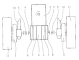
- FIG. 1 is a spatial representation of the arrangement of the drive system
- FIG. 2 is a diagrammatic arrangement of the differential of the service brake and planetary gears.
- FIG. 1
- a prime mover 1 drives a reduction gear 2 .
- the reduction gear 2 is a front drive, not shown, which makes it possible to dispose the output of the gear above the height of the tandem housing 3 .
- the reduction gear 2 has a housing part 4 , on its output, which is either connected with the main housing of the reduction gear 2 or made integrally with it. At least one differential and service brakes are situated in the housing part 4 .
- the output of the housing part 4 is connected with the drive train in the tandem housings 3 via universal shafts 5 .
- the tandem housings 3 are supported directly by a chassis of the vehicle (not shown).
- a compact drive system for tandem axles is thus provided in which the reduction gear 2 is disposed between the tandem housings 3 and in which the prime mover 1 can be situated above the tandem housing 3 and thus a compact drive results in the longitudinal direction and in the transverse direction.
- FIG. 2 [0011]FIG. 2:
- a prime mover drives a reduction gear 2 can be designed, for example, as a powershift transmission with or without a torque converter or as a continuously variable transmission.
- a differential 6 which can also be lockably designed, is situated in a housing part 4 of the reduction gear 2 .
- Service brakes 7 are connected with the outputs of the differential 6 .
- Planetary gears 8 are rear-mounted on the service brakes 7 .
- Universal shafts 5 which actuate the drive train of the tandem housings 3 , are connected with the output 9 .
- the tandem housings 3 are supported by the vehicle chassis 10 and carry the driving wheels 11 of the vehicle. When a lockable differential 6 is used, it is controlled by control of the reduction gear 2 .
Landscapes
- Engineering & Computer Science (AREA)
- Chemical & Material Sciences (AREA)
- Combustion & Propulsion (AREA)
- Transportation (AREA)
- Mechanical Engineering (AREA)
- Arrangement Of Transmissions (AREA)
- Motor Power Transmission Devices (AREA)
Abstract
In a drive system for tandem axles a prime mover (1) drives a reduction gear (2) in the housing (4) of which one differential (6), service brakes (7) and planetary gears (8) are situated. The output of the reduction gear (2) is connected, via universal shafts, in an easy manner with the drive train of the tandem housing (3). It is thus possible to situate the tandem housing (3) in the vehicle chassis (10).
Description
- Tandem axles are often used in working machines such as graders and forest tractors. On each side of the mid-section of an axle, a tandem housing carrying the driving wheels is connected. A differential and rear-mounted service brakes are often situated in the mid-section of the axle. The wheels on the front axle, such as in graders, are often driven by hydrostatic engines.
- DE 41 20 801 C2 discloses a drive system for tandem axles where one axle mid-section always supports the tandem housing and has one differential and service brakes. On the tandem housings, wheel hubs are held which accommodate the driving wheels. The differential, which is located in the mid-section of the axle, is driven via a universal shaft. The transportation and installation of said whole tandem axle, which consists of the axle mid-section and the two tandem housings, is very costly and when said tandem axle is used in different vehicles each time at least the axle mid-section has to be changed.
- The problem on which this invention is based is to provide a drive system for tandem axles which stands out by a compact mounting and a simple assembly in the vehicle.
- The problem is solved by a drive system for tandem axles according to the preamble and including also the characteristic features of the main claim.
- According to the invention, a prime mover drives a reduction gear. Said reduction gear can be designed as a mechanical transmission with or without a hydrodynamic torque converter, as a power distribution gear having, for example, one hydrostatic and one mechanical power branch, or as a hydrostatic transmission. The output of the gear is directly connected with a differential on the output sides of which service brakes are situated. The differential and the service brakes are located in one housing directly connected with the housing of the reduction gear. It is also possible to design the housing of the reduction gear and the housing where the differential and the service brakes are situated integrally. Preferably planetary gears are rear-mounted on the service brakes and are likewise situated in the housing where the differential and the service brakes are placed. The differential is preferably designed as a non-slip differential which can be controlled by the gear control at the same time. The tandem housings are directly supported in the chassis of the vehicle, the drive train being non-rotatably connected in the tandem housings via universal shafts with the output of the differential. The reduction gear preferably has a front drive which makes situating the prime mover above the tandem housing possible. By the differential, the service brakes and optionally a differential lock, which is the same as rear-mounted planetary gears being integratedly disposed on the gear output, it is possible easily to install the complete tandem housing with its drive train in the chassis and connect them via universal shafts with the gear. The installation, the same as the transportation and mounting of the structural parts, are hereby considerably simplified. With the gear being directly located between the tandem housings, the drive system can be designed more compact, since no more space needs be available between the axle mid-section and the gear for eventually required universal shafts. The service brakes, which in an integrated manner are disposed in the tandem housing, can also be designed as wet-running multi-disc brakes cooled by the lubricant of the gear. A separate cooling circuit for the service brakes is thus eliminated.
- Other features are to be understood from the description of the figures which show:
- FIG. 1 is a spatial representation of the arrangement of the drive system; and
- FIG. 2 is a diagrammatic arrangement of the differential of the service brake and planetary gears.
- FIG. 1:
- A
prime mover 1 drives areduction gear 2. In thereduction gear 2 is a front drive, not shown, which makes it possible to dispose the output of the gear above the height of thetandem housing 3. Thereduction gear 2 has ahousing part 4, on its output, which is either connected with the main housing of thereduction gear 2 or made integrally with it. At least one differential and service brakes are situated in thehousing part 4. The output of thehousing part 4 is connected with the drive train in thetandem housings 3 viauniversal shafts 5. Thetandem housings 3 are supported directly by a chassis of the vehicle (not shown). A compact drive system for tandem axles is thus provided in which thereduction gear 2 is disposed between thetandem housings 3 and in which theprime mover 1 can be situated above thetandem housing 3 and thus a compact drive results in the longitudinal direction and in the transverse direction. - FIG. 2:
- A prime mover, not shown, drives a
reduction gear 2 can be designed, for example, as a powershift transmission with or without a torque converter or as a continuously variable transmission. Adifferential 6, which can also be lockably designed, is situated in ahousing part 4 of thereduction gear 2.Service brakes 7 are connected with the outputs of thedifferential 6.Planetary gears 8 are rear-mounted on theservice brakes 7.Universal shafts 5, which actuate the drive train of thetandem housings 3, are connected with theoutput 9. Thetandem housings 3 are supported by thevehicle chassis 10 and carry thedriving wheels 11 of the vehicle. When alockable differential 6 is used, it is controlled by control of thereduction gear 2. It is thus possible, in a simple manner, to install thetandem housing 3 in the vehicle and dispose it in different positions of the vehicle.Reference numerals 1 prime mover 7 service brakes 2 reduction gear 8 planetary gears 3 tandem housing 9 output 4 housing part 10 vehicle chassis 5 universal shaft 11 driving wheels 6 differential
Claims (6)
1. Drive system for tandem axles having one prime mover (1) which is connected with an input of a reduction gear (2), the output (9) of which is connected via a differential (6) with driving wheels (11), having service brakes (7) which are connected with outputs of said differential (6) and tandem housings (3) through which said driving wheels (11) are connected with a vehicle chassis (10), characterized in that said differential (6) and said service brakes (7) are located in a housing (4) which is connected with said reduction gear (2) or designed integrally therewith.
2. Drive system for tandem axles according to claim 1 , characterized in that on said differential (6) and said service brakes (7) one planetary gear (8) is respectively rear-mounted.
3. Drive system for tandem axles according to claim 2 , characterized in that said planetary gears (8) are situated in said housing (4) of said reduction gear (2).
4. Drive system for tandem axles according to claim 1 , characterized in that said tandem housings (3) are directly supported in the vehicle chassis (10) and connected with said output (9) of said differential (6) via universal shafts (5).
5. Drive system for tandem axles according to claim 1 , characterized in that said service brakes (7) are cooled by coolants of said reduction gear (2).
6. Drive system for tandem axles according to claim 1 , characterized in that said differential (6) is a non-slip differential which can be controlled by a control of said reduction gear (2).
Applications Claiming Priority (2)
| Application Number | Priority Date | Filing Date | Title |
|---|---|---|---|
| DE10215692.1 | 2002-04-10 | ||
| DE10215692A DE10215692A1 (en) | 2002-04-10 | 2002-04-10 | Drive device for tandem axles |
Publications (2)
| Publication Number | Publication Date |
|---|---|
| US20030192733A1 true US20030192733A1 (en) | 2003-10-16 |
| US6848533B2 US6848533B2 (en) | 2005-02-01 |
Family
ID=28458681
Family Applications (1)
| Application Number | Title | Priority Date | Filing Date |
|---|---|---|---|
| US10/352,271 Expired - Fee Related US6848533B2 (en) | 2002-04-10 | 2003-01-27 | Drive system for tandem axles |
Country Status (2)
| Country | Link |
|---|---|
| US (1) | US6848533B2 (en) |
| DE (1) | DE10215692A1 (en) |
Families Citing this family (2)
| Publication number | Priority date | Publication date | Assignee | Title |
|---|---|---|---|---|
| US20070270317A1 (en) * | 2006-05-19 | 2007-11-22 | Milner Jeffrey L | Power Transmission Fluids |
| US8016068B2 (en) * | 2008-10-23 | 2011-09-13 | Caterpillar Inc. | System and method for load balancing in a tandem wheel arrangement |
Citations (3)
| Publication number | Priority date | Publication date | Assignee | Title |
|---|---|---|---|---|
| US5443430A (en) * | 1994-05-02 | 1995-08-22 | Neuberne H. Brown, Jr. | Spur gear differential for a vehicle |
| US6089357A (en) * | 1997-09-30 | 2000-07-18 | Jackson; David C. | Dual piston swing brake system for cranes |
| US6478706B1 (en) * | 1999-12-17 | 2002-11-12 | Caterpillar Inc | Planetary steering differential |
Family Cites Families (3)
| Publication number | Priority date | Publication date | Assignee | Title |
|---|---|---|---|---|
| DE2522542C3 (en) * | 1975-05-21 | 1979-11-15 | Valmet Oy, Helsinki | Drive arrangement of a motor vehicle |
| DE4120801A1 (en) * | 1991-06-24 | 1993-01-21 | Neunkirchner Masch Achsen | DRIVE DEVICE FOR TANDEMAXES |
| US6053837A (en) | 1997-10-15 | 2000-04-25 | Neunkirchener Maschinen - Und Achsenfabrik Gmbh & Co. Kg | Drive unit for a tandem axle |
-
2002
- 2002-04-10 DE DE10215692A patent/DE10215692A1/en not_active Withdrawn
-
2003
- 2003-01-27 US US10/352,271 patent/US6848533B2/en not_active Expired - Fee Related
Patent Citations (3)
| Publication number | Priority date | Publication date | Assignee | Title |
|---|---|---|---|---|
| US5443430A (en) * | 1994-05-02 | 1995-08-22 | Neuberne H. Brown, Jr. | Spur gear differential for a vehicle |
| US6089357A (en) * | 1997-09-30 | 2000-07-18 | Jackson; David C. | Dual piston swing brake system for cranes |
| US6478706B1 (en) * | 1999-12-17 | 2002-11-12 | Caterpillar Inc | Planetary steering differential |
Also Published As
| Publication number | Publication date |
|---|---|
| US6848533B2 (en) | 2005-02-01 |
| DE10215692A1 (en) | 2003-10-23 |
Similar Documents
| Publication | Publication Date | Title |
|---|---|---|
| US4523493A (en) | Transmission gear for transverse mounting and motor vehicle with transmission gear mounted therein | |
| US7316627B2 (en) | Integrated two-speed motor | |
| US6902026B2 (en) | Wheel type traveling and operating vehicle | |
| EP2934936B1 (en) | Agricultural vehicle transmission | |
| GB2168015A (en) | Transmission arrangement of service vehicle | |
| EP1176045A3 (en) | Control system for all-wheel drive vehicle | |
| US20190186618A1 (en) | Automated mechanical transmission and system for medium-duty commercial electric vehicles | |
| US4572026A (en) | Gearbox for a vehicle | |
| ATE236029T1 (en) | INTEGRATED POWER DISTRIBUTION TRANSMISSION FOR 4WD TRACTORS | |
| US20080245585A1 (en) | Vehicle Drive Line | |
| US20210046820A1 (en) | Auxiliary power take-off assembly | |
| EP4343171A1 (en) | A transmission arrangement | |
| US3679016A (en) | Vehicle provided with four wheel drive system | |
| CN117227424A (en) | Electrically driven transaxles and commercial vehicles for all-terrain commercial vehicles | |
| US6848533B2 (en) | Drive system for tandem axles | |
| US2858713A (en) | Multi-speed drive train for vehicle | |
| US5611242A (en) | Clutch unit arrangement in a tractor power take-off | |
| US10759397B2 (en) | Vehicle drive train braking | |
| WO2014096450A1 (en) | Agricultural vehicle transmission | |
| US7252173B2 (en) | Differential gear for a vehicle | |
| CZ38087U1 (en) | Additional gearbox | |
| WO2014096451A1 (en) | Vehicle transmission | |
| GB2297068A (en) | Drive for the wheels of a trailer | |
| GB2475082A (en) | PTO gearbox with an aperture that receives a driveshaft in a different configuration | |
| EP0787616A2 (en) | Hydromechanic transmission device arranged between drive shaft and one or more driven shafts |
Legal Events
| Date | Code | Title | Description |
|---|---|---|---|
| AS | Assignment |
Owner name: ZF FRIEDRICHSHAFEN AG, GERMANY Free format text: ASSIGNMENT OF ASSIGNORS INTEREST;ASSIGNOR:BECK, HERMANN;REEL/FRAME:013715/0219 Effective date: 20021119 |
|
| FEPP | Fee payment procedure |
Free format text: PAYOR NUMBER ASSIGNED (ORIGINAL EVENT CODE: ASPN); ENTITY STATUS OF PATENT OWNER: LARGE ENTITY |
|
| REMI | Maintenance fee reminder mailed | ||
| LAPS | Lapse for failure to pay maintenance fees | ||
| STCH | Information on status: patent discontinuation |
Free format text: PATENT EXPIRED DUE TO NONPAYMENT OF MAINTENANCE FEES UNDER 37 CFR 1.362 |
|
| FP | Lapsed due to failure to pay maintenance fee |
Effective date: 20090201 |